2AXNCBS450WIRELESS FULL-DUPLEX INTERCOM
Shanghai Naya Intelligence Technology Co. , Ltd.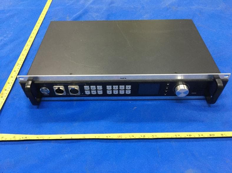
Click to zoom
Application Details
- Equipment Class
- TNB - Licensed Non-Broadcast Station Transmitter
- Date of Grant
- Oct 27, 2020
- Application Purpose
- Original Equipment
- Date of Application
- Oct 27, 2020
- Equipment Note
- WIRELESS FULL-DUPLEX INTERCOM
- Frequency Range
- 470.40000000 - 550.00000000
- Country
- China
Documents & Files
Document Text
Text extracted from the exhibit documents filed with the FCC. Open a document above to read the original.
Users Manual
Wireless Full Duplex Intercom System Base Station AFDI-BS450 User’s Manual Please read the manual carefully before operation Interface Description No. Item Description 1 Power button Press the Power button, the button light is on and the device is started. Press again the device is turned off. 2 Headset interface External cannon-type headset 3 MIC interface External gooseneck shaped microphone 4 Use headphone to speak and listen. Use gooseneck shaped microphone to speak Belt-packs isolated mode. Turn on the button light, all belt-packs are unable to talk with each other except base station. Group mode. Turn on the button light, now the digital keypad numbers indicate group numbers. Each group could talk internally, but unable to talk with other groups. Base station notices belt-packs. The selected belt-packs screen will flash when pressing the key continuously. Base station speaker button. The speaker is turned on when the button light is on. Digital keypad ( 1-8 ) You can talk to any person or groups no more than 8 at the same time by pressing certain digital buttons. 5 LCD Screen Display related data 6 “Confirm” button. Press to enter menu “Up” button. Move left to change data “Down” button. Move right to change data “Exit” button. Exit menu 7 VOLUME Adjust volume of the headset/speaker. Screw clockwise to enlarge volume. 8 SPEAKER When using a gooseneck shaped or handhold microphone, sound could be played by SPEAKER. No. Item Description 9 Antenna interface External N type connector antenna interface 10 Tally interface External tally cable to connect with video switcher 11 COM port RS232 port. Connected with computer by configuration cable. 12 UART port UART tally input. 13 LAN interface Connect Internet. Connected with Ethernet cable. 14 2W gain knob 2-wire audio gain knob. IN is audio gain input. OUT is audio gain Output 15 2W interface 2-wire audio interface 16 4W interface 4-wire audio interface and RS485 communication interface 17 4W gain knob 4-wire audio gain knob. IN is audio gain input. OUT is audio gain output 18 AUX IN gain knob Audio input gain knob 19 AUX IN interface Audio input interface 20 AUX OUT interface Audio output interface 21 AUX OUT gain knob Audio output gain knob 22 Power interface AC 110/220V power interface Note: This device must operate with a minimum distance of 20 cm between the radiator and user body. Preparations Step 1 Antenna installation. Install the antenna on the base, then plug the connector into the ANT interface of the base station. Step 2 Power cable connection. Plug one end of the power cable connector into the base station power interface, and another end into AC 110/220V power socket. Step 3 Headset and microphone installation. Plug connectors of headset and microphone into corresponding interface as required. Step 4 (Please ignore this step if you don’t need tally function) Base station and switcher connection. Plug one end of the tally cable connector into the base station tally interface, and another end into video switcher tally interface. Step 5 Turn on the base station. The lights of digital keypad (1-8) will be lit up. Then press or button to speak by headphone or microphone. Press button to turn on the speaker. Adjust the VOLUME knob to a certain level. Step 6 Speak by headphone microphone or goose-neck shaped microphone. Topological diagram Intercom System No limit for belt-pack quantity. It supports 8 belt-packs to talk simultaneously. Tally System It supports 12 red and 12 green tally signals. It could support 15 red and 15 green or 32 red tally signals in special situation. Interface Description Headphone Interface is XLR Male, which connected with headphone. Microphone Interface is XLR Female, which connected with Goose-neck shaped Microphone. Tally Interface is DB25 Male, which connected with common tally cable to receive tally signal from video switcher. It supports 12 red and 12 green tally signals. NO. Description NO. Description 1 1 Red 14 1 Green 2 2 Red 15 2 Green 3 3 Red 16 3 Green 4 4 Red 17 4 Green 5 5 Red 18 5 Green 6 6 Red 19 6 Green 7 7 Red 20 7 Green 8 8 Red 21 8 Green 9 9 Red 22 9 Green 10 10 Red 23 10 Green 11 11 Red 24 11 Green 12 12 Red 25 12 Green 13 GND Interface Description RS232 Interface is DB9 Female, which connected with RS232 cable to receive RS232 tally signal. UART Interface is 3.5mm socket, which connected with special cable to receive UART tally signal. 2W Interface is 3 wire XLR Male for audio signal. Interface Description 4W Interface is XLR internet socket for 4 wire audio signal or RS485 communication. AUX IN Interface is 3 wire XLR Female for analog audio input. AUX OUT Interface is 3 wire XLR Male for analog audio signal output. Screen Prompt Description Channel Display base station channel. Internet Display Internet status. It will be lit up when connected internet. Group Mode Display the status of group mode. It will be lit up when group mode is turned on. In this situation, the numbers on digital keypad indicate Group ID. Group mode and belt-pack isolation mode can’t be turned on at the same time. Turn on group mode, one group can’t talk with another group. Each member of group could talk within his group. Base station could talk with all member of any group. If a group ID on digital pad is turned off, the group can’t communicate with the base station. But the member of group could talk within group. Belt-pack Isolation Mode Display the status of belt-pack isolation mode. It will be lit up when belt-pack isolation mode is turned on. In this situation, all belt-packs are unable to communicate with each other. Belt-pack isolation mode and group mode can’t be turned on at the same time. Common Mode It will be lit up if group mode and belt-pack isolation mode are turned off. In this situation, the numbers on digital keypad indicate belt-pack ID. All belt-packs and base station are able to communicate with each other. If a belt-pack ID on digital pad is turned off. The belt-pack can’t communica…
Text truncated - open the document above for the full version.
Cover Letter(s)
Shanghai Naya Intelligence Technology Co. , Ltd. Room 802, Building D, No.7001 Zhongchun Road, Minhang District, Shanghai, China TEL: +86-13774303927 FAX: Series Models Description FCC ID: 2AXNCBS450 Date: Oct. 22, 2020 Federal Communications Commission Authorization and Evaluation Division 7435 Oakland Mills Road Columbia, MD 21046 To whom it may concern: The device (Product Name: WIRELESS FULL-DUPLEX INTERCOM) Models Name: AFDI-BS450, FDI-BS350 and FDI-BS340 have same electrical, PCB and BOM, only the model’s name different for marketing requirements. Sincerely, Deng Feng / Shanghai Naya Intelligence Technology Co. , Ltd.
ID Label/Location Info
FCC ID Label Information 1. Label location: 2. FCC ID Label: FCC ID: 2AXNCBS450 FCCID Label Location
Internal Photos
Antenna port
RF Exposure Info
RF Exposure evaluation According to 447498 D01 General RF Exposure Guidance v05 The 1-g and 10-g SAR test exclusion thresholds for 100 MHz to 6 GHz at test separation distances ≤ 50 mm are determined by: [(max. power of channel, including tune-up tolerance, mW)/(min. test separation distance, mm)] ·[√f(GHz)] ≤ 3.0 for 1-g SAR and ≤ 7.5 for 10-g extremity SAR, where f(GHz) is the RF channel transmit frequency in GHz Power and distance are rounded to the nearest mW and mm before calculation The result is rounded to one decimal place for comparison At separation distance of ≥50 mm: pt=21.70dBm =147.91mW at 470.4MHz So (147.91mW/50mm)x √0.4704GHz = 2.03<7.5 Then SAR evaluation is not required
Test Report
Shenzhen CTL Testing Technology Co., Ltd. Tel: +86-755-89486194 E-mail: [email protected] TEST REPORT FCC PART 74H Report Reference No. ....................... : CTL2009041013-WF Compiled by: ( position+printed name+signature) Happy Guo (File administrators) Tested by: ( position+printed name+signature) Nice Nong (Test Engineer) Approved by: ( position+printed name+signature) Ivan Xie (Manager) Product Name ............................. : WIRELESS FULL-DUPLEX INTERCOM Model/Type reference ................ : AFDI-BS450 List Model(s) ............................... : FDI-BS350, FDI-BS340 Trade Mark .................................. : N/A FCC ID ......................................... : 2AXNCBS450 Applicant’s name ....................... : Shanghai Naya Intelligence Technology Co. , Ltd. Address of applicant .................. : Room 802, Building D, No.7001 Zhongchun Road, Minhang District, Shanghai, China Test Firm ..................................... : Shenzhen CTL Testing Technology Co., Ltd. Address of Test Firm ................. : Floor 1-A, Baisha Technology Park, No.3011, Shahexi Road, Nanshan District, Shenzhen, China 518055 Test specification ....................... : Standard ...................................... : FCC Part 74 Subpart H—Low Power Auxiliary Stations TRF Originator ............................. : Shenzhen CTL Testing Technology Co., Ltd. Master TRF .................................. : Dated 2011-01 Date of receipt of test item .............. : Sep. 15, 2020 Date of sampling ............................... : Sep. 15, 2020 Date of Test Date .............................. : Sep. 15, 2020 - Oct. 14, 2020 Date of Issue ..................................... : Oct. 15, 2020 Result ................................................. : Pass Shenzhen CTL Testing Technology Co., Ltd. All rights reserved. This publication may be reproduced in whole or in part for non-commercial purposes as long as the Shenzhen CTL Testing Technology Co., Ltd. is acknowledged as copyright owner and source of the material. Shenzhen CTL Testing Technology Co., Ltd. takes no responsibility for and will not assume liability for damages resulting from the reader's interpretation of the reproduced material due to its placement and context. V1.0 Page 2 of 33 Report No.: CTL2009041013-WF TEST REPORT Test Report No. : CTL2009041013-WF Oct. 15, 2020 Date of issue Equipment under Test : WIRELESS FULL-DUPLEX INTERCOM Sample No. CTL200904101-1-S003 Model /Type : AFDI-BS450 Listed Models : FDI-BS350, FDI-BS340 Applicant : Shanghai Naya Intelligence Technology Co. , Ltd. Address : Room 802, Building D, No.7001 Zhongchun Road, Minhang District, Shanghai, China Manufacturer : Shanghai Naya Intelligence Technology Co. , Ltd. Address : Room 802, Building D, No.7001 Zhongchun Road, Minhang District, Shanghai, China Test result Pass * * In the configuration tested, the EUT complied with the standards specified page 5. The test report merely corresponds to the test sample. It is not permitted to copy extracts of these test result without the written permission of the test laboratory. V1.0 Page 3 of 33 Report No.: CTL2009041013-WF ** Modified History ** Revisions Description Issued Data Report No. Remark Version 1.0 Initial Test Report Release 2020-10-15 CTL2009041013-WF Tracy Qi V1.0 Page 4 of 33 Report No.: CTL2009041013-WF Table of Contents Page 1 S U M M A R Y ............................................................................ 5 1.1 Test Standards 5 1.2 Test Description 5 1.3 Test Facility 6 1.4 Statement of the measurement uncertainty 6 2 G E N E R A L I N F O R M A T I O N ......................................................... 7 2.1 Environmental conditions 7 2.2 General Description of EUT 7 2.3 Description of Test Modes and Test Frequency 7 2.4 Equipments Used during the Test 8 2.5 Related Submittal(s) / Grant(s) 8 2.6 Modifications 8 3 T E S T C O N D I T I O N S A N D R E S U L T S ............................................. 9 3.1 Output Power Measurement 9 3.2 Modulation Characteristics 10 3.3 Operating Bandwidth and Emissions Mask 17 3.4 Emission Mask 20 3.5 Field Strength of Emission 22 3.6 Frequency Stability Measurement 24 4 T E S T S E T U P P H O T O S O F T H E E U T ......................................... 26 5 E X T E R N A L A N D I N T E R N AL PH O T O S O F T H E E U T ...................... 27 V1.0 Page 5 of 33 Report No.: CTL2009041013-WF 1 S U M M A R Y 1.1 Test Standards The tests were performed according to following standards: FCC Part 74 Subpart H—Low Power Auxiliary Stations TIA-603-E (2016)-Land Mobile FM or PM Communications Equipment Measurement and Performance Standards FCC Part 2: FREQUENCY ALLOCA-TIONS AND RADIO TREATY MAT-TERS; GENERAL RULES AND REG-ULATIONS ANSI C63.10:2013: –American National Standard for Testing Unlicensed Wireless Devices ANSI C63.4: 2014: –American National Standard for Methods of Measurement of Radio-Noise Emissions from Low-Voltage Electrical and Electronic Equipment in the Range of 9 kHz to 40GHz Range of 9 kHz to 40GHz 1.2 Test Description FCC Rules Description of Test Test Result FCC section 74.861(e)(1), FCC part 2, section 2.1046 RF Output Power Complies FCC section 74.861(e)(3) , FCC part 2, section 2.1047 Modulation Characteristic Complies FCC section 74.861(e)(5) , FCC part 2, section 2.1049 Emission Bandwidth Complies FCC section 74.861(e)(6) , FCC part 2, section 2.1053 Field Strength of Spurious Emission Complies FCC section 74.861(e)(4) , FCC part 2, section 2.1055 Frequency Stability Complies V1.0 Page 6 of 33 Report No.: CTL2009041013-WF 1.3 Test Facility 1.3.1 Address of the test laboratory Shenzhen CTL Testing Technology Co., Ltd. Floor 1-A, Baisha Technology Park, No. 3011, Shahexi Road, Nanshan, Shenzhen 518055 China There is one 3m semi-anechoic chamber and two line conducted labs for final test. The Test Sites meet the requirements in documents ANSI C63.4 and CISPR 32/EN 55032 requirements. 1.3.2 Laboratory accreditation…
Text truncated - open the document above for the full version.
Contact Information
Applicant
Feng Deng
Test Firm
Shenzhen CTL Testing Technology Co., Ltd.Tracy Qi
[email protected]86-755-89486194
Technical Specifications
| # | Rule Parts | Frequency Range | Power Output | Emission | Tolerance |
|---|---|---|---|---|---|
| 1 | 74 | 470.4 MHz - 550 MHz | 147.90 mW | 111KF1E | 37.0000000000 ppm |
Other Applications from Shanghai Naya Intelligence Technology Co. , Ltd.
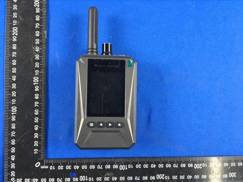
2AXNCPT420
Oct 27, 2020WIRELESS FULL-DUPLEX INTERCOM
Equipment Class
TNT - Licensed Non-Broadcast Transmitter Worn on Body