2AXNCPT420WIRELESS FULL-DUPLEX INTERCOM
Shanghai Naya Intelligence Technology Co. , Ltd.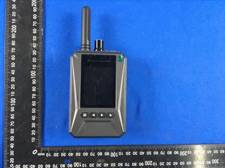
Click to zoom
Application Details
- Equipment Class
- TNT - Licensed Non-Broadcast Transmitter Worn on Body
- Date of Grant
- Oct 27, 2020
- Application Purpose
- Original Equipment
- Date of Application
- Oct 27, 2020
- Equipment Note
- WIRELESS FULL-DUPLEX INTERCOM
- Frequency Range
- 470.40000000 - 550.00000000
- Country
- China
Documents & Files
Document Text
Text extracted from the exhibit documents filed with the FCC. Open a document above to read the original.
Users Manual
1 Wireless Full-Duplex Intercom AFDI-PT420 User’s Manual Please read the manual carefully before operation 2 Chapter 1 Function Display Switch / Volume Screw the switch clockwise to turn on the device and enlarge the volume, Antenna Receive and transfer signal.。 Headphone Headphone Interface Chapter 2 Description Indicator Red light flicker indicates transfer signal and green light flicker indicates receive signal. If the tally function is enabled by tally setting, the indicator will display tally signal in priority, namely continuously red(PGM) or green(PVW). MUTE Press the key to transfer audio signal once red light flicker. Now you could speak by headphone microphone. Press again to close the function. Screen Display information Setting Menu / Confirm Left Right Exit TALLY Transfer tally signal to tally screen by a connection cable (Not headphone interface) Charging Indicator Red light indicates charging, green light indicates fully charged. 3 Type-C Charging Interface. 1/4 Screw Hole Fix the device to tripod. Chapter 3 Installation Step 1 Hold the antenna and screw clockwise to tighten. Step 2 Put the headphone connector into the interface. Step 3 Screw the volume key clockwise to turn on the device and enlarge the volume. Step 4 Press the MUTE key to talk by headphone microphone when the indicator with red light flicker. 4 Chapter 4 Display Screen Channel Display the present channel. Battery Level Display the battery level. The icon will be empty when the level is too low. Now the belt-pack is unable to talk. Please charge soon. Belt-pack ID Display the belt-pack ID, the range is 1-99. Group ID. Display the group ID, the range is 1-8. Microphone The icon indicates that the belt-pack microphone function is available, otherwise it is unavailable. If the icon changes to , it means that the base station has forbidden the belt-pack to talk. Speaker The icon indicates that the belt-pack is receiving the audio signal from other belt-packs or base station. Group Mode The icon indicates that the base station has set grouping function. The group ID could be changed as required. Only the belt-packs at the same group could talk with each other. Belt-pack Isolation The icon indicates that the base station has set belt-pack Isolation function. Now the belt-packs are unable to talk with each other except the base station. Caller The icon indicates that the base station or other belt-packs are sending audio signal. The number indicates the belt-pack ID that are sending audio signal. The number 0 indicates the base station, 1-8 indicates the belt-pack ID 1-8, and 9 indicates belt-pack 9-99. 5 Chapter 5 Settings Press the button, the screen will prompt “Press Return Key into menu”. Then press the button to enter the menu. Select the following 11 mode settings by pressing and buttons. Includes Channel Setting, Background Sound Level, Voice Control Setting, Headset Type Setting, Noise Suppression Level, TALLY Setting, MIC Return, ID Setting, Group Setting, Language Setting, Preload configuration. Press button to enter a setting. Press button to return to the previous menu after setting. Press button again to exit menu. Channel Setting Enter the menu and choose “Channel Setting”. Then press “Confirm” button to enter the setting. Choose channel by pressing “Left” and “Right” button. Press “Exit” button to return to the previous menu after setting. It is advised to set a big channel spacing (30 channels or more) if two or more channels are used for different teams at same place. Background Sound Level Enter the menu and choose “Background Sound Level”. Then press “Confirm” button to enter the setting. Choose suitable level by pressing “Left” and “Right” button. There are 3 levels, namely 0, 1, 2. Select the suitable level according to the background noise level. Press “Exit” button to return to the previous menu after setting. The factory default setting is level 1, which is suitable for most situation. Level 0 is suitable for a silent situation, just speak with a low voice. Level 1 is suitable for most situation, you should speak with a loud voice. (Factory default setting) Level 2 is suitable for a noisy situation, you should speak with a roar. (Note: No need to change the setting in general. The voice may be intermittent if the level is too high in a relatively quiet situation) 6 Voice Control Setting Enter the menu and choose “Voice Control Setting”. Then press “Confirm” button to enter the setting. Choose suitable mode by pressing “Left” and “Right” button. There are 2 modes, namely VOX Mode and PTT Mode. Select the suitable level according to the situation. Press “Exit” button to return to the previous menu after setting. MUTE Mode means press the “MUTE” button only once to speak, press again to finish. PTT Mode means press the “MUTE” button and keep holding to speak. Release the button to finish. 7 Headset Type Enter the menu and choose “Headset Type”. Then press “Confirm” button to enter the setting. Choose suitable headset type by pressing “Left” and “Right” button. There are 2 headset types, namely headphone and earphone. Choose the suitable headset type as required. Press “Exit” button to return to the previous menu after setting. Headphone is suitable for noisy situation. Earphone is suitable for quiet situation. Noise Suppression Level Enter the menu and choose “Noise Suppression Level”. Then press “Confirm” button to enter the setting. Choose suitable level by pressing “Left” and “Right” button. There are 6 levels, namely 0, 1%, 2%, 3%, 4%, 5%. Choose the suitable level as required. Press “Exit” button to return to the previous menu after setting. The setting allows the headset to suppress a certain level of the background noise received from other belt-packs or the base station. The default setting is level 5. (Suppress the noise lower than 5%. Only those voice volume surpass 5% will be heard.) 8 Tally Setting Enter the menu and choose “Tally Setting”. Then press “Confirm” button to enter t…
Text truncated - open the document above for the full version.
Cover Letter(s)
CONFIDENTIALITY REQUEST for Certification Service in USA Federal Communication Commission Equipment Authorization Division, Application Processing Branch 7435 Oakland Mills Road Columbia, MD 21046 Date: 2020/10/22 TO WHOM IT MAY CONCERN Pursuant to Paragraphs §0.457 and 0.459 of the Commission’s Rules (47 C.F.R.) and Section §552(b)(4) of the Freedom of Information Act, we requests confidentiality for the following products: FCC ID Model name 2AXNCPT420 AFDI-PT420, HDI-PT190, FDI-PT320 For the product stated above, we request that the following information be held confidential; Exhibits Long-Term Confidentiality Short-Term Confidentiality Short-Term Confidentiality Days External Photos Internal Photos Block Diagram Schematics Test Setup Photos User’s Manual Parts List Tune Up Operational Descriptions The long-term confidentiality exhibits contain our trade secrets and proprietary information that could be of benefit to our competitors. The short-term confidentiality on the basis of ensuring that business sensitive information remains confidential until the actual marketing of our new device. If you have any questions, please feel free to contact me at the address shown below. Sincerely, Name: Deng feng Company: Shanghai Naya Intelligence Technology Co. , Ltd. Address: Room 802, Building D, No.7001 Zhongchun Road, Minhang District, Shanghai, China Phone: +86-13774303927 Fax: N/A E-Mail: [email protected]
External Photos
Antenna
ID Label/Location Info
FCC ID Label Information 1. Label location: 2. FCC ID Label: FCC ID:2AXNCPT420 FCCID Label Location
RF Exposure Info
Any reproduction of this document must be done in full. No single part of this document may be reproduced without permission from STS, All Test Data Presented in this report is only applicable to presented Test sample. ShenZhen STS Test Services Co.,Ltd. A 1/F, Building B, Zhuoke Science Park, No.190 Chongqing Road, HepingShequ, Fuyong Sub-District, Bao’an District, Shenzhen, Guang Dong, China TEL: +86-755 3688 6288 FAX: +86-755 3688 6277 E-mail:[email protected] FCC SAR TEST REPORT Report No.: STS2009285H01 Issued for Shanghai Naya Intelligence Technology Co. , Ltd. Room 802, Building D, No.7001 Zhongchun Road, Minhang District, Shanghai Product Name: WIRELESS FULL-DUPLEX INTERCOM Brand Name: N/A Model Name: AFDI-PT420 Series Model: HDI-PT190, FDI-PT320 FCC ID 2AXNCPT420 Test Standard: ANSI/IEEE Std. C95.1 FCC 47 CFR Part 2 ( 2.1093) IEEE 1528: 2013 Max. Report SAR (1g): Face up : 0.015 W/kg Back Touch : 0.041 W/kg S T L A B S Page 2 of 26 Report No.: STS2009285H01 Test Report Certification Applicant’s name ................. : Shanghai Naya Intelligence Technology Co. , Ltd. Address ................................. : Room 802, Building D, No.7001 Zhongchun Road, Minhang District, Shanghai Manufacture's Name ............ : Shanghai Naya Intelligence Technology Co. , Ltd. Address ................................. : Room 802, Building D, No.7001 Zhongchun Road, Minhang District, Shanghai Product Description Product Name ........................ : WIRELESS FULL-DUPLEX INTERCOM Brand Name ........................... : N/A Model Name ......................... : AFDI-PT420 Series Model .......................... : HDI-PT190, FDI-PT320 Standards ............................. : ANSI/IEEE Std. C95.1 FCC 47 CFR Part 2 ( 2.1093) IEEE 1528: 2013 The device was tested by Shenzhen STS Test Services Co., Ltd. in accordance with the measurement methods and procedures specified in KDB 865664 The test results in this report apply only to the tested sample of the stated device/equipment. Other similar device/equipment will not necessarily produce the same results due to production tolerance and measurement uncertainties. Date of Test ........................................... : Date (s) of performance of tests ............. : 28 Sept. 2020 Date of Issue .......................................... : 30 Sept. 2020 Test Result .............................................. : Pass Testing Engineer : ( Aaron Bu) Technical Manager : (Sean She) Authorized Signatory : (Vita Li) Page 3 of 26 Report No.: STS2009285H01 Table of Contents 1. General Information 4 1.1 EUT Description 4 1.2 Test Environment 5 1.3 Test Factory 5 2. Test Standards and Limits 6 3. SAR Measurement System 7 3.1 Definition of Specific Absorption Rate (SAR) 7 3.2 SAR System 7 4. Tissue Simulating Liquids 10 4.1 Simulating Liquids Parameter Check 10 5. SAR System Validation 12 5.1 Validation System 12 5.2 Validation Result 12 6. SAR Evaluation Procedures 13 7. EUT Test Position 14 8. Uncertainty 15 8.1 Measurement Uncertainty 15 8.2 System validation Uncertainty 16 9. Conducted Power Measurement 17 Test Result 17 10. EUT And Test Setup Photo 18 10.1 Setup Photo 18 11. SAR Result Summary 20 11.1 Summary of Measurement Result 20 12. Equipment List 21 Appendix A. System Validation Plots 22 Appendix B. SAR Test Plots 24 Appendix C. Probe Calibration and Dipole Calibration Report 26 Page 4 of 26 Report No.: STS2009285H01 1. General Information 1.1 EUT Description Equipment WIRELESS FULL-DUPLEX INTERCOM Brand Name N/A Model name AFDI-PT420 Series Model HDI-PT190, FDI-PT320 Model Difference Only different in model name Device Category Portable Product stage Production unit RF Exposure Environment Population/Uncontrolled Hardware Version N/A Software Version N/A Frequency Range 470.4MHz-550MHz(1~200 channel) Channel Spacing 400KHz Max. Reported SAR(1g): Test Channel Face up (W/kg) Back Touch (W/kg) CH 1 0.046 0.081 CH 100 0.041 0.070 CH 200 0.042 0.075 Modulation Type: FSK Antenna Specification: External antenna Note: 1. The EUT battery must be fully charged and checked periodically during the test to ascertain uniform power Page 5 of 26 Report No.: STS2009285H01 1.2 Test Environment Ambient conditions in the SAR laboratory: Items Required Temperature (°C) 18-25 Humidity (%RH) 30-70 1.3 Test Factory ShenZhen STS Test Services Co.,Ltd. A 1/F, Building B, Zhuoke Science Park, No.190 Chongqing Road, HepingShequ, Fuyong Sub-District, Bao’an District, Shenzhen, Guang Dong, China FCC Registration No.: 625569 A2LA Certificate No.: 4338.01 IC Registration No.: 12108A Page 6 of 26 Report No.: STS2009285H01 2. Test Standards and Limits No. Identity Document Title 1 47 CFR Part 2 Frequency Allocations and Radio Treaty Matters; General Rules and Regulations 2 ANSI/IEEE Std. C95.1-1992 IEEE Standard for Safety Levels with Respect to Human Exposure to Radio Frequency Electromagnetic Fields, 3 kHz to 300 GHz 3 IEEE Std. 1528-2013 Recommended Practice for Determining the Peak Spatial-Average Specific Absorption Rate (SAR) in the Human Head from Wireless Communications Devices: Measurement Techniques 4 FCC KDB 447498 D01 v06 Mobile and Portable Device RF Exposure Procedures and Equipment Authorization Policies 5 FCC KDB 865664 D01 v01r04 SAR Measurement 100 MHz to 6 GHz 6 FCC KDB 865664 D02 v01r02 RF Exposure Reporting 7 FCC KDB 643646 D001 SAR Test Reduction Considerations for Occupational PTT Radios (A). Limits for Occupational/Controlled Exposure (W/kg) Whole-Body Partial-Body Hands, Wrists, Feet and Ankles 0.4 8.0 20.0 (B). Limits for General Population/Uncontrolled Exposure (W/kg) Whole-Body Partial-Body Hands, Wrists, Feet and Ankles 0.08 1.6 4.0 NOTE: Whole-Body SAR is averaged over the entire body, partial-body SAR is averaged over any 1 gram of tissue defined as a tissue volume in the shape of a cube. SAR for hands, wrists, feet and ankles is averaged over any 10 grams of tissue defined as a tissue volume in the shape of a cube. Population/Uncontrolled Environmen…
Text truncated - open the document above for the full version.
RF Exposure Info
Ref : ACR.262.3.20.MVGB.A SHENZHEN STS TEST SERVICES CO., LTD. 1/F, BUILDING 2, ZHUOKE SCIENCE PARK,No.190, CHONGQING ROAD, FUYONG STREET, BAO’ AN DISTRICT, SHENZHEN,GUANGDONGCHINA MVG COMOSAR REFERENCE DIPOLE FREQUENCY: 450 MHZ SERIAL NO.: SN 30/14 DIP0G450-330 07/14/2020 Summary: This document presents the method and results from an accredited SAR reference dipole calibration performed in MVG. using the CALIPROBE test bench. for use with a MVG COMOSAR system only. The test results covered by accreditation are traceable to the International System of Units(SI). SAR Reference Dipole Calibration Report Calibrated at MVG Z.I. de la pointe du diable Technopôle Brest Iroise - 295 avenue Alexis de Rochon 29280 PLOUZANE - FRANCE Calibretion date: 07/14/2020 Page: 1/11 SAR REFERENCE DIPOLE CALIBRATION REPORT Ref: ACR.262.3.20.MVGB.A Name Function Date Signature Prepared by : Jérôme LUC Technical Manager 7/28/2020 Checked by : Jérôme LUC Technical Manager 7/28/2020 Approved by : Yann Toutain Laboratory Director 7/28/2020 Customer Name Distribution : Shenzhen STS Test Services Co., Ltd. Issue Date Modifications A 7/28/2020Initial release Page: 2/11 Template_ACR.DDD.N.YY.MVGB.ISSUE_COMOSAR Probe vH This document shall not be reproduced, except in full or in part, without the written approval of MVG. The information contained herein is to be used only for the purpose for which it is submitted and is not to be released in whole or part without written approval of MVG. Name Jérôme LUC SAR REFERENCE DIPOLE CALIBRATION REPORT Ref: ACR.262.3.20.MVGB.A TABLE OF CONTENTS 1 Introduction ................................................................................................................ 4 2 Device Under Test ..................................................................................................... 4 3 Product Description ................................................................................................... 4 3.1 General Information _______________________________________________________ 4 4 Measurement Method ................................................................................................ 5 4.1 Return Loss Requirements __________________________________________________ 5 4.2 Mechanical Requirements ___________________________________________________ 5 5 Measurement Uncertainty .......................................................................................... 5 5.1 Return Loss ______________________________________________________________ 5 5.2 Dimension Measurement ___________________________________________________ 5 5.3 Validation Measurement ____________________________________________________ 5 6 Calibration Measurement Results .............................................................................. 6 6.1 Return Loss and Impedance In Head Liquid ____________________________________ 6 6.2 Return Loss and Impedance In Body Liquid ____________________________________ 6 6.3 Mechanical Dimensions ____________________________________________________ 6 7 Validation measurement ............................................................................................ 7 7.1 Head Liquid Measurement __________________________________________________ 7 7.2 SAR Measurement Result With Head Liquid ____________________________________ 8 7.3 Body Liquid Measurement __________________________________________________ 9 7.4 SAR Measurement Result With Body Liquid __________________________________ 10 8 List of Equipment .................................................................................................... 11 Page: 2/11 Template_ACR.DDD.N.YY.MVGB.ISSUE_COMOSAR Probe vH T his document shall not be reproduced, except in full or in part, without the written approval of MVG. The information contained herein is to be used only for the purpose for which it is submitted and is not to be released in whole or part without written approval of MVG. Page: 3/11 Template_ACR.DDD.N.YY.MVGB.ISSUE_COMOSAR Probe vH This document shall not be reproduced, except in full or in part, without the written approval of MVG. The information contained herein is to be used only for the purpose for which it is submitted and is not to be released in whole or part without written approval of MVG. SAR REFERENCE DIPOLE CALIBRATION REPORT Ref: ACR.262.3.20.MVGB.A 1 INTRODUCTION This document contains a summary of the requirements set forth by the IEEE 1528, OET 65 Bulletin C and CEI/IEC 62209 standards for reference dipoles used for SAR measurement system validations and the measurements that were performed to verify that the product complies with the fore mentioned standards. 2 DEVICE UNDER TEST Device Under Test Device Type COMOSAR 450 MHz REFERENCE DIPOLE Manufacturer MVG Model SID450 Serial Number SN 30/14 DIP0G450-330 Product Condition (new / used) New A yearly calibration interval is recommended. 3 PRODUCT DESCRIPTION 3.1 GENERAL INFORMATION MVG’s COMOSAR Validation Dipoles are built in accordance to the IEEE 1528, OET 65 Bulletin C and CEI/IEC 62209 standards. The product is designed for use with the COMOSAR test bench only. Figure 1 – MVG COMOSAR Validation Dipole Page: 4/11 Template_ACR.DDD.N.YY.MVGB.ISSUE_COMOSAR Probe vH This document shall not be reproduced, except in full or in part, without the written approval of MVG. The information contained herein is to be used only for the purpose for which it is submitted and is not to be released in whole or part without written approval of MVG. SAR REFERENCE DIPOLE CALIBRATION REPORT Ref: ACR.262.3.20.MVGB.A 4 MEASUREMENT METHOD The IEEE 1528, OET 65 Bulletin C and CEI/IEC 62209 standards provide requirements for reference dipoles used for system validation measurements. The following measurements were performed to verify that the product complies with the fore mentioned standards. 4.1 RETURN LOSS REQUIREMENTS The dipole used for SAR system validation measurements and checks must have a return loss of -20 dB or better. Th…
Text truncated - open the document above for the full version.
Test Report
Shenzhen CTL Testing Technology Co., Ltd. Tel: +86-755-89486194 E-mail: [email protected] TEST REPORT FCC PART 74H Report Reference No. ....................... : CTL2009041012-WF Compiled by: ( position+printed name+signature) Happy Guo (File administrators) Tested by: ( position+printed name+signature) Nice Nong (Test Engineer) Approved by: ( position+printed name+signature) Ivan Xie (Manager) Product Name ............................. : WIRELESS FULL-DUPLEX INTERCOM Model/Type reference ................ : AFDI-PT420 List Model(s) ............................... : HDI-PT190, FDI-PT320 Trade Mark .................................. : N/A FCC ID ......................................... : 2AXNCPT420 Applicant’s name ....................... : Shanghai Naya Intelligence Technology Co. , Ltd. Address of applicant .................. : Room 802, Building D, No.7001 Zhongchun Road, Minhang District, Shanghai, China Test Firm ..................................... : Shenzhen CTL Testing Technology Co., Ltd. Address of Test Firm ................. : Floor 1-A, Baisha Technology Park, No.3011, Shahexi Road, Nanshan District, Shenzhen, China 518055 Test specification ....................... : Standard ...................................... : FCC Part 74 Subpart H—Low Power Auxiliary Stations TRF Originator ............................. : Shenzhen CTL Testing Technology Co., Ltd. Master TRF .................................. : Dated 2011-01 Date of receipt of test item .............. : Sep. 15, 2020 Date of sampling ............................... : Sep. 15, 2020 Date of Test Date .............................. : Sep. 15, 2020 - Oct. 14, 2020 Date of Issue ..................................... : Oct. 15, 2020 Result ................................................. : Pass Shenzhen CTL Testing Technology Co., Ltd. All rights reserved. This publication may be reproduced in whole or in part for non-commercial purposes as long as the Shenzhen CTL Testing Technology Co., Ltd. is acknowledged as copyright owner and source of the material. Shenzhen CTL Testing Technology Co., Ltd. takes no responsibility for and will not assume liability for damages resulting from the reader's interpretation of the reproduced material due to its placement and context. V1.0 Page 2 of 31 Report No.: CTL2009041012-WF TEST REPORT Test Report No. : CTL2009041012-WF Oct. 15, 2020 Date of issue Equipment under Test : WIRELESS FULL-DUPLEX INTERCOM Sample No. CTL200904101-1-S002 Model /Type : AFDI-PT420 Listed Models : HDI-PT190, FDI-PT320 Applicant : Shanghai Naya Intelligence Technology Co. , Ltd. Address : Room 802, Building D, No.7001 Zhongchun Road, Minhang District, Shanghai, China Manufacturer : Shanghai Naya Intelligence Technology Co. , Ltd. Address : Room 802, Building D, No.7001 Zhongchun Road, Minhang District, Shanghai, China Test result Pass * * In the configuration tested, the EUT complied with the standards specified page 5. The test report merely corresponds to the test sample. It is not permitted to copy extracts of these test result without the written permission of the test laboratory. V1.0 Page 3 of 31 Report No.: CTL2009041012-WF ** Modified History ** Revisions Description Issued Data Report No. Remark Version 1.0 Initial Test Report Release 2020-10-15 CTL2009041012-WF Tracy Qi V1.0 Page 4 of 31 Report No.: CTL2009041012-WF Table of Contents Page 1 S U M M A R Y ............................................................................ 5 1.1 Test Standards 5 1.2 Test Description 5 1.3 Test Facility 6 1.4 Statement of the measurement uncertainty 6 2 G E N E R A L I N F O R M A T I O N ......................................................... 7 2.1 Environmental conditions 7 2.2 General Description of EUT 7 2.3 Description of Test Modes and Test Frequency 7 2.4 Equipments Used during the Test 8 2.5 Related Submittal(s) / Grant(s) 8 2.6 Modifications 8 3 T E S T C O N D I T I O N S A N D R E S U L T S ............................................. 9 3.1 Output Power Measurement 9 3.2 Modulation Characteristics 10 3.3 Operating Bandwidth and Emissions Mask 17 3.4 Emission Mask 20 3.5 Field Strength of Emission 22 3.6 Frequency Stability Measurement 24 4 T E S T S E T U P P H O T O S O F T H E E U T ......................................... 26 5 E X T E R N A L A N D I N T E R N AL P H O T O S O F T H E E U T ...................... 27 V1.0 Page 5 of 31 Report No.: CTL2009041012-WF 1 S U M M A R Y 1.1 Test Standards The tests were performed according to following standards: FCC Part 74 Subpart H—Low Power Auxiliary Stations TIA-603-E (2016)-Land Mobile FM or PM Communications Equipment Measurement and Performance Standards FCC Part 2: FREQUENCY ALLOCA-TIONS AND RADIO TREATY MAT-TERS; GENERAL RULES AND REG-ULATIONS ANSI C63.10:2013: –American National Standard for Testing Unlicensed Wireless Devices ANSI C63.4: 2014: –American National Standard for Methods of Measurement of Radio-Noise Emissions from Low-Voltage Electrical and Electronic Equipment in the Range of 9 kHz to 40GHz Range of 9 kHz to 40GHz 1.2 Test Description FCC Rules Description of Test Test Result FCC section 74.861(e)(1), FCC part 2, section 2.1046 RF Output Power Complies FCC section 74.861(e)(3) , FCC part 2, section 2.1047 Modulation Characteristic Complies FCC section 74.861(e)(5) , FCC part 2, section 2.1049 Emission Bandwidth Complies FCC section 74.861(e)(6) , FCC part 2, section 2.1053 Field Strength of Spurious Emission Complies FCC section 74.861(e)(4) , FCC part 2, section 2.1055 Frequency Stability Complies V1.0 Page 6 of 31 Report No.: CTL2009041012-WF 1.3 Test Facility 1.3.1 Address of the test laboratory Shenzhen CTL Testing Technology Co., Ltd. Floor 1-A, Baisha Technology Park, No. 3011, Shahexi Road, Nanshan, Shenzhen 518055 China There is one 3m semi-anechoic chamber and two line conducted labs for final test. The Test Sites meet the requirements in documents ANSI C63.4 and CISPR 32/EN 55032 requirements. 1.3.2 Laboratory accreditatio…
Text truncated - open the document above for the full version.
Contact Information
Applicant
Feng Deng
Test Firm
Shenzhen CTL Testing Technology Co., Ltd.Tracy Qi
[email protected]86-755-89486194
Technical Specifications
| # | Rule Parts | Frequency Range | Power Output | Emission | Tolerance |
|---|---|---|---|---|---|
| 1 | 74 | 470.4 MHz - 550 MHz | 212.80 mW | 111KF1E | 36.0000000000 ppm |
Other Applications from Shanghai Naya Intelligence Technology Co. , Ltd.
2AXNCBS450
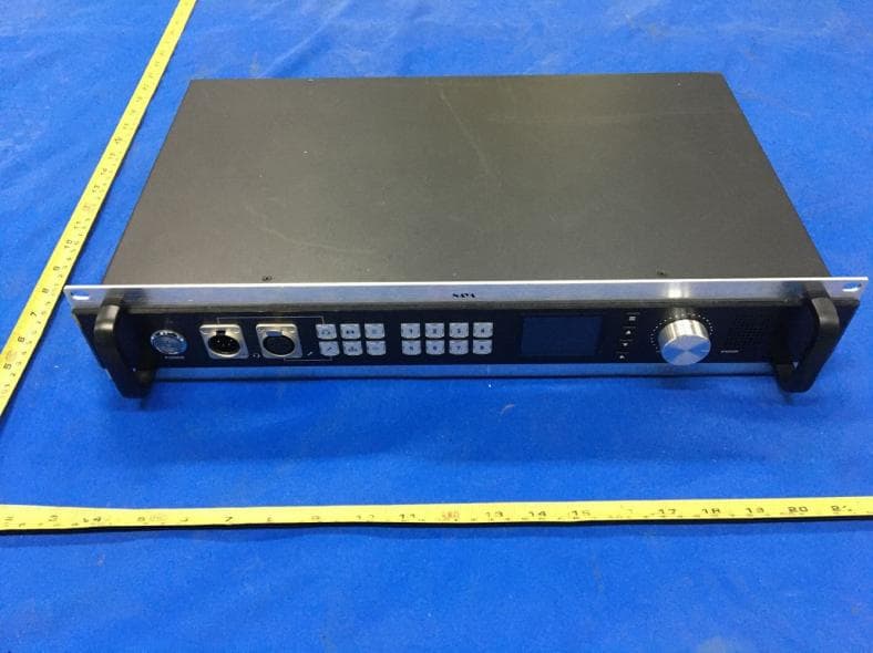
Oct 27, 2020WIRELESS FULL-DUPLEX INTERCOM
Equipment Class
TNB - Licensed Non-Broadcast Station Transmitter