FCCID.CO- FCC ID Database
HomeCompaniesEquipment ClassesSearch

© 2026 FCC ID Database. All rights reserved.

AboutContactData sourced from FCC public records
  1. Home/
  2. Head Electronics BV/
  3. 2AXRUP191114

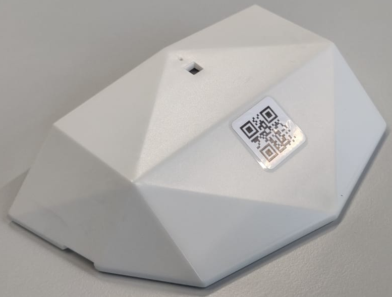
2AXRUP191114Wireless room occupancy and climate sensor

Head Electronics BV
Wireless room occupancy and climate sensor - FCC ID 2AXRUP191114 - Head Electronics BV
Click to zoom

Application Details

Equipment Class
DTS - Digital Transmission System
Date of Grant
May 03, 2021
Application Purpose
Original Equipment
Date of Application
May 02, 2021
Equipment Note
Wireless room occupancy and climate sensor
Frequency Range
902.00000000 - 928.00000000
Company
Head Electronics BV
Country
Netherlands

Documents & Files

Select a file to view
Users Manual

↗

Block Diagram

↗

Cover Letter(s)

↗

External Photos

↗

ID Label/Location Info

↗
↗

Internal Photos

↗

Operational Description

↗

RF Exposure Info

↗

Test Report

↗

Test Setup Photos

↗

Document Text

Text extracted from the exhibit documents filed with the FCC. Open a document above to read the original.

Users Manual

OfficeSense Sensor Installation manual Version 1.1, March 6, 2020 Page 2 OfficeSense sensor installation v1.1 Contents General description ............................................................................................. 3 Intended readership ........................................................................................... 3 What makes the OfficeSense sensor series unique? ................................................ 3 Sensor handling ................................................................................................. 3 Technical information ......................................................................................... 4 Generic ................................................................................................................ 4 Presence .............................................................................................................. 4 Desk .................................................................................................................... 4 Comfort ................................................................................................................ 5 Sensor operation ................................................................................................ 6 Installation guide ............................................................................................... 7 Presence Sensor and Comfort Sensor .................................................................... 7 Check Package contents ................................................................................... 7 Getting the sensors ready ................................................................................. 8 Mounting the Comfort Sensor .......................................................................... 9 Mounting the Presence Sensor .......................................................................10 Presence sensor placement recommendations ....................................................11 Additional information .....................................................................................11 Desk Sensor .....................................................................................................12 Check Package contents ..................................................................................12 Preparing the desk sensor ................................................................................12 Mounting the sensor ........................................................................................13 Sensor placement recommendations .................................................................14 Additional information .....................................................................................16 Installing ‘Barcode to Sheet’ application ...............................................................18 Registering a sensor with the ‘Barcode to Sheet’ app .............................................21 Installation procedure reference .......................................................................23 Preparation checklist ..........................................................................................23 Deployment steps ..............................................................................................23 Regulations .......................................................................................................24 Legal notices .....................................................................................................24 Federal Communication Commission Interference Statement ..................................24 Non-modifications statement ..............................................................................24 Declaration of conformity ...................................................................................24 Page 3 OfficeSense sensor installation v1.1 Introduction General description OfficeSense is a workspace utilization sensor solution for LoRaWAN wireless networks to measure occupancy of conference rooms, desks and other office spaces, and for monitoring the indoor office environment. The OfficeSense series consist of a Presence sensor, a Desk sensor, an two different Comfort sensors. The Presence sensor measures room occupancy, temperature and humidity. The Desk sensor is used to detect desk availability and the Comfort sensor measures a mix of different environmental variables including CO 2 , temperature, humidity, luminance and noise levels. The OfficeSense sensor device is battery powered and designed to be long lasting and it is easily deployable. Intended readership This installation manual is intended for the building manager, installation coordinator and the installation engineer who physically installs the OfficeSense sensor. What makes the OfficeSense sensor series unique? • Intelligent presence sensor: o Sending presence information, not motion data o Extremely low data rates, extremely low presence updates conserving battery power o Built-in intelligence prevents false-positive errors o Highly sensitive and low power PIR (passive infra-red) sensor • OfficeSense Comfort (temperature, humidity and CO 2 ) o Send updates in a set time interval or; o Send updates on significant difference in measurement • Power consumption o 4 regular AA batteries, available anywhere o Improved deep-sleep capabilities: only airtime when needed • Over the Air (OTA) configuration o Default sensor configuration adjustable to needs o OTA firmware updates (future release) • Application switch to adjust settings o E.g. modifiable sample times and deep sleep interval timers • Remote monitoring for sensor maintenance o Last seen indication o Battery level indication o Metadata functions also includes sensor ID, sensor type, software version, heartbeat interval, etc. Sensor handling The OfficeSense sensors may be damaged by improper storage or handling. The sensor elements are particula…

Text truncated - open the document above for the full version.

Block Diagram

I2C (100KHz) [1] LoRa & MCU module (32MHz TCXO) (32.768KHz XTAL) UART (9600) CO2 sensorMicrophone Antenna (Fc = 890MHz) (BW = 40MHz) Mode indicator LED [Red & Green] Ambient light sensor Signal conditioning (Amplify, rectify & filter) 3.3V Power supply 3.3 to 6.4V Batteries (4 x AA 1.5V) EEPROMVOC sensor Temperature & Humidity sensor VBAT VBAT Measurement Project: Officesense 2.0 Client: Capgemini Author: Tom Klijn Project number: PXXXXXX Revision: V01 Date: 10-06-2020 Block diagram: Officesense 2.0 [1] Transmit center frequency is variant dependent: Center frequency is 868MHz for Europe and 915MHz for USA Motion sensor

Cover Letter(s)

FCC, Request for non-disclosure Date: 21-Nov-2018 RF_501, Issue 8 Page 1 of 1 Company Name: Head Electronics BV Address: Ambachtsweg 17 City: Katwijk Country: Netherlands To: Telefication B.V., Dept. FCC TCB Edisonstraat 12A 6902 PK ZEVENAAR The Netherlands Subject: Request f or conf identiality FCC ID: 2AXRUP191114 Reference number: ###### Dear FCC TCB, 1. Long-Term Confidentiality Pursuant to 47 CFR Section 0.459(a) & (b), we hereby requests non-disclosure and conf idential treatment of the f ollowing materials submitted in support of FCC certif ication application: Bill(s) of Material Block Diagrams Operational Description Schematic Diagrams Tune-up Procedure Above materials contain secrets, proprietary and technical inf ormation, which would customarily be guarded f rom competitors under 47 CFR, section 0.457(d)(2). Disclosure or publication or any portion of this company confidential material to other parties could cause substantial competitive harm and provide unjustif ied benef its for competitors. 2. Short-Term Confidentiality (STC) Pursuant to Public Notice DA 04-1705 of the Commission’s policy, in order to comply with the marketing regulations in 47 CFR §2.803 and the importation rules in 47 CFR §2.1204, applicant hereby requests Short-Term Conf idential treatment of the f ollowing materials (See notes below): Internal Photos User’s Manual Test Set-up Photos External Photos Justif ication: Date: 19-04-2021 Name and signature of applicant: Tom Klijn Notes: 1) A document or type of document can only have ONE type of confidentiality! 2) Short-Term confidentiality is in principle for 45 days from date of grant; it can be extended max 3 times (total time 180 days max.)! The planned date should stated in the RF731 application form. 3) FCC must be informed when marketing begins earlier. 4) Release takes place automatically thus extension must be requested in time. Telefication does not remind you of this! 5) Request for extension or for release must be received by Telefication at least 7 days before date of actual marketing or before expiration of the STC period

External Photos

Page 1 of 3 External Photo Module Product name : OfficeSense FCC ID : 2AXRUP191114 IC ID : 26960-OFFICESENSE Test report No. 200801065 Test report No. 200801065 Page 1 of 3 Table of Contents 1 External Photos ....................................................................................................................................... 2 1.1 Front/3D View ....................................................................................................................................... 2 1.2 Back view ............................................................................................................................................... 3 Test report No. 200801065 Page 2 of 3 1 External Photos 1.1 Front/3D View Test report No. 200801065 Page 3 of 3 1.2 Back view

ID Label/Location Info

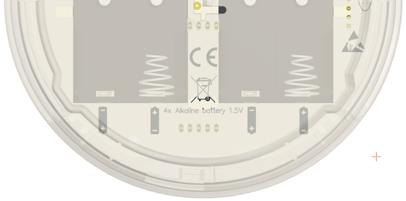
Officesense_2 markings information PCB silkscreen The PCB silkscreen contains the static device information. • Manufacturer information • Compliance ID's and logo's • Battery orientation and information Device label The printed label contains dynamic information. • LoRaWAN DEVEUI in QR and text format • Model ID, variant, region information Model ID Model/variant/region P191112 Officesense_2_Comfort_EU P191110 Officesense_2_Presence_EU P191114 Officesense_2_Comfort_USA P191115 Officesense_2_Presence_USA P191117 Officesense_2_Comfort_IN P191118 Officesense_2_Presence_IN Certification/Registration Number: 26960-OFFICESENSE

Internal Photos

Page 1 of 3 Internal Photo Module Test report No. 200801065 Product name : OfficeSense FCC ID : 2AXRUP191114 IC ID : 26960-OFFICESENSE Test report No. 200801065 Page 1 of 3 Table of Contents 1 Internal Photos ........................................................................................................................................ 2 1.1 Front PCB 1 view .................................................................................................................................... 2 1.2 Back PCB 1 view ..................................................................................................................................... 2 1.3 Back PCB 2 view ..................................................................................................................................... 3 Test report No. 200801065 Page 2 of 3 1 Internal Photos 1.1 Front PCB 1 view 1.2 Back PCB 1 view Test report No. 200801065 Page 3 of 3 1.3 Back PCB 2 view

Operational Description

FCC / ISED Transmission information Both devices “Officesense 2” and “Desksense” share the same transmitter and network stack, the transmission specification are identical. Modulation / Operating frequency and datarate information: The modulation type used is called LoRa. This is a Frequency-Hopping, Spread-Spectrum (FHSS) modulation. And functions as the physical/datalink network layers. On top of this the LoRaWAN network stack is implemented functioning as the network transport and session layers (The network stack used is developed and tested by Semtech according to the LoRawan specifications 1.0.3). These documents contain a detailed description of the modulation used, operating frequency en data rate. For more information refer to attachments: “lorawan1.0.3.pdf” “lorawan1.0.3 Regional parameters.pdf” For USA and Canada, the devices are hardcoded to use the “US902-928MHz ISM Band” LoRaWAN configuration, refer to section 2.5 of “lorawan1.0.3 Regional parameters.pdf” for more information. Example: Antenna information: “Officesense 2” Model ID Model/variant/region Notes P191114 Officesense_2_Comfort_USA Same HWID for Canada P191115 Officesense_2_Presence_USA Same HWID for Canada *The RF-sections of the PCB for both models are identical. The “Officesense 2” employs a planar (PCB-antenna) inverted-F antenna. The antenna is part of the PCB and cannot be changed or disconnected from the transmitter. “Desksense” The “Desksense” uses a planar (PCB-antenna) meandering monopole antenna. The antenna is part of the PCB and cannot be changed or disconnected from the transmitter. Model ID Model/region Notes P190202 Desksense_US Same HWID for Canada

RF Exposure Info

Page 1 of 5 FCC SAR Exclusion Report Product name : OfficeSense Applicant : Head Electronics B.V. FCC ID : 2AXRUP191114 Test report No. : 200801065 005 Ver 2.0 Report number: 200801065 005 Ver 2.0 Page 1 of 5 Laboratory information Accreditation Telefication complies with the accreditation criteria for test laboratories as laid down in ISO/IEC 17025:2017. The accreditation covers the quality system of the laboratory as well as the specific activities as described in the authorized annex bearing the accreditation number L021 and is granted on 30 November 1990 by the Dutch Council For Accreditation (RvA: Raad voor Accreditatie). Telefication is designated by the FCC as an Accredited Test Firm for compliance testing of equipment subject to Certification under Parts 15 & 18. The Designation number is: NL0001. Telefication is a Wireless Device Testing laboratory recognized by Innovation, Science and Economic Development Canada to test to Canadian radio equipment requirements. Telefication is a registered Conformity Assessment body (CAB) under the Japan-EC MRA (Agreement on Mutual Recognition between Japan and the European Community). The registration number is: 201. Documentation The test report must always be reproduced in full; reproduction of an excerpt only is subject to written approval of the testing laboratory. The documentation of the testing performed on the tested devices is archived for 10 years at Telefication Netherlands. Testing Location Test Site Test Site location Kiwa Telefication Wilmersdorf 50 7327 AC Apeldoorn The Netherlands Report number: 200801065 005 Ver 2.0 Page 2 of 5 Revision History Version Date Remarks By v0.5 07/12/2020 Draft Version K.K V1.0 23-02-2021 Initial release version PvW V2.0 08-04-2021 Updated FCC ID PvW Report number: 200801065 005 Ver 2.0 Page 3 of 5 Table of Contents Revision History .............................................................................................................................................. 2 1 General Description ................................................................................................................................. 4 1.1 Applicant ................................................................................................................................................ 4 1.2 Manufacturer ........................................................................................................................................ 4 1.3 Tested Equipment Under Test (EUT) ..................................................................................................... 4 1.4 SAR Measurement Evaluation ............................................................................................................... 5 1.4.1 Maximum Output Power ................................................................................................................... 5 1.4.2 SAR Testing Exclusions ...................................................................................................................... 5 1.5 Summary ................................................................................................................................................ 5 Report number: 200801065 005 Ver 2.0 Page 4 of 5 1 General Description 1.1 Applicant Client name: Head Electronics B.V. Address: Ambachtsweg 17 2222 AH Katwijk NETHERLANDS Contact name: Tom Klijn E-mail: [email protected] 1.2 Manufacturer Client name: Head Electronics B.V. Address: Ambachtsweg 17 Katwijk NETHERLANDS Contact name: René Huiskens E-mail: [email protected] 1.3 Tested Equipment Under Test (EUT) Product name: OfficeSense Brand name: Head Electronics B.V. Product type: Wireless battery powered room occupancy and climate sensor FCC ID: 2AXRUP191114 Model(s): OfficeSense Software version: V2.1 Hardware version: V03 Date of receipt: 10-11-2020 Tests started: 01-12-2020 Testing ended: 04-12-2020 Report number: 200801065 005 Ver 2.0 Page 5 of 5 1.4 SAR Measurement Evaluation 1.4.1 Maximum Output Power The maximum radiated power including tune-up tolerance is shown as below. Mode Max Power Level LoRa 12,18 dBm * from Telefication report 200801065 004. 1.4.2 SAR Testing Exclusions According to KDB 447498 D01, the SAR test exclusion condition is based on source-based time- averaged maximum conducted output power, adjusted for tune-up tolerance, and the minimum test separation distance required for the exposure conditions. The SAR exclusion threshold is determined by the following formula. 1. For the test separation distance <= 50 mm When the minimum test separation distance is < 5 mm, a distance of 5 mm is applied to determine SAR test exclusion. 2. For the test separation distance > 50 mm, and the frequency at 100 MHz to 1500 MHz 3. For the test separation distance > 50 mm, and the frequency at > 1500 MHz to 6 GHz Mode Max. Tune- up Power (dBm) Max. Tune- up Power (mW) Ant. to Surface (mm) Calculated Result (mW) Require SAR Testing? LoRa 12.18 dBm 16.5 mW 200 905 No Note: 1. When separation distance <= 50 mm and the calculated result shown in above table is <= 3.0, the SAR testing exclusion is applied. 2. When separation distance > 50 mm and the device output power is less than the calculated result (power threshold, mW) shown in above table, the SAR testing exclusion is applied. 1.5 Summary Since the SAR testing for all device orientations apply SAR test exclusion per KDB 447498, SAR testing for this device is not required.

Test Report

FCC and IC Test report for parts 15.109, 15.209, 15.247 RSS-247, RSS-Gen Product name : OfficeSense Applicant : Head Electronics B.V. FCC ID : 2AXRUP191114 IC ID : 26960-OFFICESENSE Test report No. : 200801065 004 Ver 2.0 Report number: 200801065 004 Ver 2.0 Page 1 of 28 Laboratory information Accreditation Telefication complies with the accreditation criteria for test laboratories as laid down in ISO/IEC 17025:2017. The accreditation covers the quality system of the laboratory as well as the specific activities as described in the authorized annex bearing the accreditation number L021 and is granted on 30 November 1990 by the Dutch Council For Accreditation (RvA: Raad voor Accreditatie). Telefication is designated by the FCC as an Accredited Test Firm for compliance testing of equipment subject to Certification under Parts 15 & 18. The Designation number is: NL0001. Telefication is a Wireless Device Testing laboratory recognized by Innovation, Science and Economic Development Canada to test to Canadian radio equipment requirements. Telefication is a registered Conformity Assessment body (CAB) under the Japan-EC MRA (Agreement on Mutual Recognition between Japan and the European Community). The registration number is: 201. Documentation The test report must always be reproduced in full; reproduction of an excerpt only is subject to written approval of the testing laboratory. The documentation of the testing performed on the tested devices is archived for 10 years at Telefication Netherlands. Testing Location Test Site Telefication BV Test Site location Wilmersdorf 50 7327 AC Apeldoorn The Netherlands +31 88998 3393 Test Site FCC NL0001 Report number: 200801065 004 Ver 2.0 Page 2 of 28 Revision History Version Date Remarks By v0.50 14-12-2020 First draft K.K. v1.00 22-02-2021 Final version PvW V2.0 18-03-2021 Expanded frequency range to cover full LoRa application Added additional RF measurements to cover delta in module test report PvW Report number: 200801065 004 Ver 2.0 Page 3 of 28 Table of Contents Revision History .............................................................................................................................................. 2 Summary of Test results .................................................................................................................................. 5 1 General Description ................................................................................................................................. 6 1.1 Applicant ................................................................................................................................................ 6 1.2 Manufacturer ........................................................................................................................................ 6 1.3 Tested Equipment Under Test (EUT) ..................................................................................................... 6 1.4 Product specifications of Equipment under test ................................................................................... 7 1.5 Environmental conditions...................................................................................................................... 7 1.6 Measurement standards ....................................................................................................................... 7 1.7 Applicable standards ............................................................................................................................. 7 1.8 Observation and remarks ...................................................................................................................... 7 1.9 Conclusions ............................................................................................................................................ 8 2 Test configuration of the Equipment Under Test ..................................................................................... 9 2.1 Test mode .............................................................................................................................................. 9 2.2 Test setups ............................................................................................................................................. 9 2.3 Equipment used in the test configuration ........................................................................................... 10 2.4 Sample calculations ............................................................................................................................. 10 3 Test results ............................................................................................................................................ 11 3.1 Radiated spurious emissions ............................................................................................................... 11 3.1.1 Limit ................................................................................................................................................. 11 3.1.2 Measurement instruments ............................................................................................................. 11 3.1.3 Test setup ........................................................................................................................................ 11 3.1.4 Test procedure ................................................................................................................................ 11 3.1.5 Measurement Uncertainty .............................................................................................................. 11 3.1.6 Results of the radiated spurious emissions measurement ............................................................. 12 3.1.7 Plots of the Radiated Spurious Emissions Measurement ................................................................ 13 3.2 Output Power Measurement ........................................…

Text truncated - open the document above for the full version.

Test Setup Photos

Page 1 of 3 Test Setup Photo Module Product name : OfficeSense FCC ID : 2AXRU-P191114 IC ID : 26960-OFFICESENSE Test report No. 200801065 Test report No. 200801065 Page 1 of 3 Contents 1 Test Setup Photos .................................................................................................................... 2 1.1 Radiated emissions measurement 9 kH z – 30 MHz ........................................................................................2 1.2 Radiated emissions measurement 30 – 1000 MHz.........................................................................................3 1.3 Radiated emissions measurement 1 – 18 GHz.................................................................................................3 Test report No. 200801065 Page 2 of 3 1 Test Setup Photos 1.1 Radiated emissions measurement 9 kHz – 30 MHz Test report No. 200801065 Page 3 of 3 1.2 Radiated emissions measurement 30 – 1000 MHz 1.3 Radiated emissions measurement 1 – 18 GHz

Contact Information

Applicant

Tom Klijn(ing.)
[email protected]0714029154Fax: +31 (0)71 - 40 30 09

Technical Contact

Head Electronics BVTom Klijn
[email protected]31 (0)6 25237695

Ambachtsweg 17 Zuid-Holland 2222AH · Netherlands

Non-Technical Contact

Head Electronics BVRene Huiskens
[email protected]31 (0)71 8001011

Test Firm

Kiwa Nederland B.V.Willem Jong
[email protected]+31 889983621

Technical Specifications

#Rule PartsFrequency RangePower Output
115C902 MHz - 928 MHz20.00 mW
Confidentiality
Long Term
Grant Notes
Power output listed is conducted. This is a portable device. The device must not be co-located or operating in conjunction with any other antenna or transmitter. End-users must be provided with transmitter operating conditions for satisfying RF exposure compliance.

Other Applications from Head Electronics BV

Wireless room occupancy and climate sensor - FCC ID 2AXRUP190201 - Head Electronics BV
2AXRUP190201

Wireless room occupancy and climate sensor

Apr 18, 2021

Equipment Class

DTS - Digital Transmission System