2AXS5-FLW3881VSA7-AWiFi module
Jiang Su Fulian Communication Technology Co., Ltd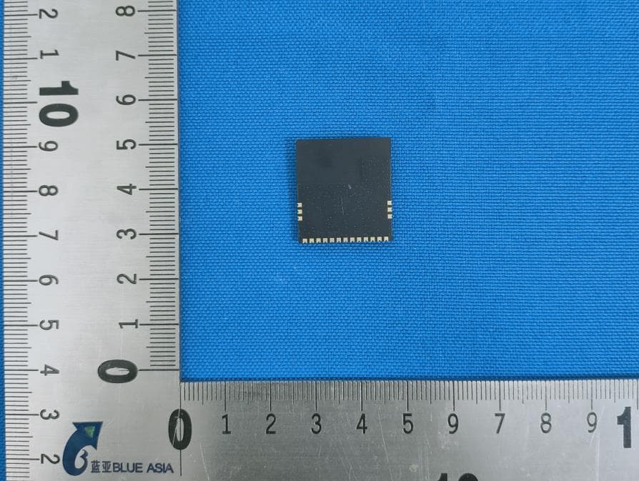
Click to zoom
Application Details
- Equipment Class
- DTS - Digital Transmission System
- Date of Grant
- Jul 25, 2021
- Application Purpose
- Original Equipment
- Date of Application
- Jul 24, 2021
- Equipment Note
- WiFi module
- Frequency Range
- 2412.00000000 - 2462.00000000
- Country
- China
Documents & Files
Document Text
Text extracted from the exhibit documents filed with the FCC. Open a document above to read the original.
Users Manual
Datasheet ModuleName:FLW3881VSA7-A Manufacture:JiangSuFulianCommunicationTechnologyCo.,Ltd ApprovedVerifyDrawVersionDate V1.02021.03.01 一、Version DatetimeVersionChangecontent 2021-03-01V1.0Initialversion 1.1.Overview Hi3881V100isahighlyintegrated2.4GHzWi-FistationchipthatpackstheIEEE802.11b/g/n basebandandRFcircuit.TheRFcircuitconsistsofthepoweramplifier(PA),lownoiseamplifier(LNA), RFbalun,antennaswitch,andpowermanagementmodule.Itsupports20MHzstandardbandwidth and5MHz/10MHznarrowbandwidth,andprovidesaphysicallayerrateupto72.2Mbit/s. TheHi3881V100Wi-Fibasebandsupportstheorthogonalfrequencydivisionmultiplexing(OFDM) technologyandisbackwardcompatiblewiththedirectsequencespreadspectrum(DSSS)and complementarycodekeying(CCK)technologies,offeringvariousdataratesdefinedintheIEEE802.11 b/g/nprotocol. Hi3881V100integratesahigh-performance32-bitmicroprocessorandprovidesSDIO2.0,UART, andGPIOinterfaces,withclockfrequencyupto50MHz.Asaslavechip,Hi3881V100runsby connectingtothemasterchipoverSDIOinterfaces. ThischipsupportsHuaweiLiteOSandLinuxOSandprovidesanopendevelopmentenvironment andafastersystemrunningenvironment. ThischipisapplicabletoIoTterminalfieldssuchasIPcameraandOTT. 1.2.Key Specifications GeneralSpecifications 1x1 2.4 GHz frequency band (channels 1–14) Wi-Fi station PHY supporting IEEE 802.11b/g/n MAC supporting IEEE802.11 d/e/h/i/k/v/w Built-in PA and LNA, integrated with TX/RX switch and balun Station (STA) and access point (AP) modes, up to six STAs as an AP WFA WPA, WFA WPA2 personal, and WPS2.0 2/3/4-line PTA solution with BT and BLE UNABLE Input voltage range: 2.3–3.6 V I/O power voltage: 1.8 V or 3.3 V RFauto-calibrationsolution PHY Features Allsingle-antennadataratesofIEEE802.11b/g/n Maximumrateof72.2Mbit/s@HT20MCS7 Standard20MHzbandwidthand5 MHz/10MHznarrowbandwidth STBCRX ShortGI MACFeatures A-MPDUandA-MSDU Blk-ACK QoS CPUSubsystem High-performance32-bitmicroprocessorwithamaximumoperatingfrequencyof160MHz Built-in352KBSRAMand288KBROM 1.3.specification Item ParameterDescription ModuleNameFLW3881VSA7-A TypeWLAN11nSDIO1T1Rmodule ChipHi3881V100 Stand802.11b/g/n Physicalfrequencyband2.4~2.4835GHz SupportOS Windows2000,XP,Vista,Win7,Linux,Mac,Android,Win CE SafetyWEP,TKIP,AES,WPA,WPA2 InterfaceSDIO1.1/2.0兼容 PowerSupplyDC3.3V(最小3.0V-最大3.6V) Operatingtemperature0~+70°C Storagetemperature-20~125°C Dimension21x23x3.3mm(±0.2mm)(IncludeShieldcover) 1.4. FunctionalBlock Diagram 图1.FLW3881VSA7-A硬件框图 1.5.Dimension 图2.FLW3881VSA7-A尺寸图 confidential 1.6.Pindescription 表1 IndexPinNamePindescription 1-3GNDGND 4VBAT3.3V 5NCNC 6VDDIO1.8-3.3V,IO Supply,Max3.6V 7GNDGND 8CHIP_ENChipEN 9GPIO02WL_DEV_WAKE_HOST 10SD_D2SD_D2 11SD_D3SD_D3 12SD_CMDSD_CMD 13SD_CLKSD_CLK 14SD_D0SD_D0 15SD_D1SD_D1 16-19GNDGND 1.7.Secondaryreflowsolderingtemperaturecurve 图3.FLW3881VSA7-AReflowsolderingtemperaturecurve 1.8.Packing Itisshippedinreelpackaging,whichisconvenientforcustomerstoSMT,built-inhumiditycardanddesiccant,vacuumedin electrostaticbags,andpackagedincartonsforshipment.Boththereelandtheouterboxareaffixedwithfactorynotesand checkoutQRcodesforeasytracking. 图4.FLW3881VSA7-APacking 1.9.Salesandtechnicalsupportinformation Ifyouneedtoconsultorpurchasethisproduct,pleasecallJiangsuFulianCommunicationTechnologyCo., Ltd.duringofficehours. Officehours:MondaytoSaturday,morning:8:00~12:00,afternoon:13:00~17:00 PostCode:212310 PhoneNumber:0511-80760088 Email:[email protected] Address:YonganCommunity,thesouthofLanlingRoad,DanyangDevelopmentDistrict, JiangsuProvince,China. (1) This device may not cause harmful interference; (2) This device must accept any interference received, including interference that may cause undesired operation. Note: This equipment has been tested and found to comply with the limits for a Class B digital device, pursuant to part 15 of the FCC Rules. These limits are designed to provide reasonable protection against harmful interference in a residential installation. This equipment generates, uses and can radiate radio frequency energy and, if not installed and used in accordance with the instructions, may cause harmful interference to radio communications. However, there is no guarantee that interference will not occur in a particular installation. If this equipment does cause harmful interference to radio or television reception, which can be determined by turning the equipment off and on, the user is encouraged to try to correct the interference by one or more of the following measures: FCC Statement FCC standards: FCC CFR Title 47 Part 15 Subpart C Section 15.247 Integral antenna , Antenna gain 1dBi This device complies with part 15 of the FCC Rules. Operation is subject to the following two conditions: (1) This device may not cause harmful interference, and (2) this device must accept any interference received, including interference that may cause undesired operation. Any Changes or modifications not expressly approved by the party responsible for compliance could void the user's authority to operate the equipment. Note: This equipment has been tested and found to comply with the limits for a Class B digital device, pursuant to part 15 of the FCC Rules. These limits are designed to pr ovide reasonable protection against harmful interference in a residential installation. This equipment generates, uses and can radiate radio frequency energy and, if not installed and used in accordance with the instructions, may cause harmful interference to radio communications. However, there is no guarantee that interference will not occur in a particular installation. If this equipment does cause harmful interference to radio or television reception, which can be determined by turning the equipment off and on, the user is encouraged to try to correct the interference by one or more of the following measures: — Reorient or relocate the receiving antenna. —Increase the separation between the equipment and receiver. —Connect the equipment into an outlet on a circuit different from that to which the re…
Text truncated - open the document above for the full version.
Attestation Statements
Compliance list INTEGRATION INSTRUCTIONS for 996369 D03 OEM the and 996369 D03 OEM by Sections 2.2 through 2.10. Requirement Yes N/A Comment 2.2 List of applicable FCC rules List the FCC rules that are applicable to the modular transmitter. These are the rules that specifically establish the bands of operation, the power, spurious emissions, and operating fundamental frequencies. DO NOT list compliance to unintentional-radiator rules (Part 15 Subpart B) since that is not a condition of a module grant that is extended to a host manufacturer. See also Section 2.10 below concerning the need to notify host manufacturers that further testing is required.3 YES Refer to instruction FCC standards: FCC CFR Title 47 Part 15 Subpart C Section 15.247 2.3 Summarize the specific operational use conditions Describe use conditions that are applicable to the modular transmitter, including for example any limits on antennas, etc. For example, if point-to-point antennas are used that require reduction in power or compensation for cable loss, then this information must be in the instructions. If the use condition limitations extend to professional users, then instructions must state that this information also extends to the host manufacturer’s instruction manual. In addition, certain information may also be needed, such as peak gain per frequency band and minimum gain, specifically for master devices in 5 GHz DFS bands. YES Refer to instruction Integral antenna , Antenna gain 1dBi 2.4 Limited module procedures If a modular transmitter is approved as a “limited module,” then the module manufacturer is responsible for approving the host environment that the limited module is used with. The manufacturer of a limited module must describe, both in the filing and in the installation instructions, the alternative means that the limited module manufacturer uses to verify that the host meets the necessary requirements to satisfy the module limiting conditions. A limited module manufacturer has the flexibility to define its alternative method to address the conditions that limit the initial approval, such as: shielding, minimum N/A Not applicable signaling amplitude, buffered modulation/data inputs, or power supply regulation. The alternative method could include that the limited module manufacturer reviews detailed test data or host designs prior to giving the host manufacturer approval. This limited module procedure is also applicable for RF exposure evaluation when it is necessary to demonstrate compliance in a specific host. The module manufacturer must state how control of the product into which the modular transmitter will be installed will be maintained such that full compliance of the product is always ensured. For additional hosts other than the specific host originally granted with a limited module, a Class II permissive change is required on the module grant to register the additional host as a specific host also approved with the module. 2.5 Trace antenna designs For a modular transmitter with trace antenna designs, see the guidance in Question 11 of KDB Publication 996369 D02 FAQ – Modules for Micro-Strip Antennas and traces. The integration information shall include for the TCB review the integration instructions for the following aspects: layout of trace design, parts list (BOM), antenna, connectors, and isolation requirements.4 a) Information that includes permitted variances (e.g., trace boundary limits, thickness, length, width, shape(s), dielectric constant, and impedance as applicable for each type of antenna); b) Each design shall be considered a different type (e.g., antenna length in multiple(s) of frequency, the wavelength, and antenna shape (traces in phase) can affect antenna gain and must be considered); c) The parameters shall be provided in a manner permitting host manufacturers to design the printed circuit (PC) board layout; d) Appropriate parts by manufacturer and specifications; e) Test procedures for design verification; and f) Production test procedures for ensuring N/A Not applicable compliance. The module grantee shall provide a notice that any deviation(s) from the defined parameters of the antenna trace, as described by the instructions, require that the host product manufacturer must notify the module grantee that they wish to change the antenna trace design. In this case, a Class II permissive change application is required to be filed by the grantee, or the host manufacturer can take responsibility through the change in FCC ID (new application) procedure followed by a Class II permissive change application. 2.6 RF exposure considerations It is essential for module grantees to clearly and explicitly state the RF exposure conditions that permit a host product manufacturer to use the module. Two types of instructions are required for RF exposure information: (1) to the host product manufacturer, to define the application conditions (mobile, portable – xx cm from a person’s body); and (2) additional text needed for the host product manufacturer to provide to end users in their end-product manuals. If RF exposure statements and use conditions are not provided, then the host product manufacturer is required to take responsibility of the module through a change in FCC ID (new application). YES Refer to instruction The modular can be installed or integrated in mobile or fix devices only. This modular cannot be installed in any portable device if without further certify such as C2PC with SAR. This modular complies with FCC RF radiation exposure limits set forth for an uncontrolled environment. This transmitter must not be colocated or operating in conjunction with any other antenna or transmitter. This modular must be installed and operated with a minimum distance of 20 cm between the radiator and user body. 2.7 Antennas A list of antennas included in the application for certification must be provided in the instructions. For modular transmitters approved as limited modules, all appli…
Text truncated - open the document above for the full version.
Cover Letter(s)
Single Modular approval Declaration letter We, Jiang Su Fulian Communication Technology Co., Ltd applies single modular approval for Product Name: WiFi Module Model:FLW3881 VSA 7-A FCC ID: 2AXS5-FLW3881 VSA 7-A According to 996369 DOl Module EquipAuth Guide v0lr04 and 15.212 requfrement: 1) The radio elements must have the radio frequency circuitry shielded. Physical c omponents and tuning capacitor(s) may be located external to the sh;eld, but must be on the module assembly; Answer: Yes, shielded. 2) T he module must have buffered modulation/data inputs to ensure that the device will comply with Part 15 r equirements with any type of input signal; Answer: Yes; All inputs to the modules are buffered through logic or microprocessor inputs. 3) The modular transmitter must have its own power supply regulation. A nswer: Yes; A low drop out regulator is used for modular power supply regulation. 4) The module must contain a permanently attached antenna, or contain a unique antennaconnector, and be marketed and operated only with specific antenna(s), per Sectionsl5.203, 15.204(b ), 15.204(c), 15.212 (a), 2.929(b ) ; An s w e r : Y e s ; D e v i c e i s e q u ipp e d w i t h i n t e g r a l a n t e n n a . (5) The module must demonstrate compliance in a stand-alone configuration; Answer: Yes, distance between modular and all A Es are bigger than J Ocm, refer to setup photo. ' (6 ) The module must be labeled with its permanently affixed FCC ID label, or use a n electronic display (See KDB Publication 784748 about labelling requirements); Answer:Yes, The modular has a permanent fixed label, and below statement was listed in the User Manual;The host device must be labeled to display the FCC ID of the module “Contains FCC ID: 2AXS5-FLW3881VSA7-A” (7) The module must comply with all specific rules applicable to the transmitter including all the conditions provided in the integration instructions by the grantee; Answer:Yes, The module comply with all specific rules applicable to the transmitter including all the conditions provided in the integration instructions by the grantee, Refer to test report and user manual . (8) The module must comply with RF exposure requirements Answer: Yes; Transmitter meets MPE calculation of 47 CFR 1.1307. Refer to MPE Reports and Refer to modular installation manual. Please contact me if you have any further questions. Thanks for your attention. Best Regards, <Signature> Name: Wei luo Title: I Company: Jiang Su Fulian Communication Technolo gy Co., Ltd
External Photos
Model No.: FLW3881VSA7-A
ID Label/Location Info
FCC ID: 2AXS5-FLW3881VSA7-A
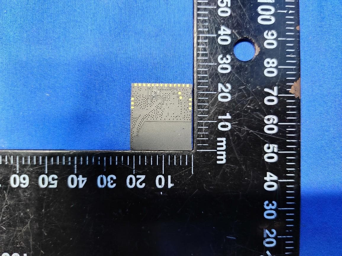
Internal Photos
Model No.: FLW3881VSA7-A
RF Exposure Info
Page 1 of 2 Product Name: WiFi Module Model No.:FLW3881VSA7-A FCC ID:2AXS5- FLW3881VSA7-A RF Exposure Evaluation 1.1 RF Exposure Compliance Requirement 1.1.1 Limits According to FCC Part1.1310: The criteria listed in the following table shall be used to evaluate the environment impact of human exposure to radio frequency (RF) radiation as specified in part1.1307(b) F= Frequency in MHz Friis Formula Friis transmission formula: Pd = (Pout*G)/(4* Pi * R 2) Where Pd = power density in mW/cm2 Pout = output power to antenna in mW G = gain of antenna in linear scale Pi = 3.1416 R = distance between observation point and center of the radiator in cm Pd id the limit of MPE, 1 mW/cm2 . If we know the maximum gain of the antenna and the total power input to the antenna, through the calculation, we will know the distance r where the MPE limit is reached. 1.1.2 Test Procedure Software provided by client enabled the EUT to transmit and receive data at lowest, middle and highest channel individually. Page 2 of 2 1.1.3 EUT RF Exposure Evaluation Antenna Gain:1.0dBi; Antenna Gain: The maximum Gain measured in fully anechoic chamber is 1.26 in linear scale. Output Power Into Antenna & RF Exposure Evaluation Distance: 2.4G WIFI: 802.11g(worst case) Channel Frequency (MHz) Max Conducted Peak Output Power (dBm) Output Power to Antenna (mW) Power Density at R = 20 cm (mW/cm 2 ) Limit Result Middle 2437 19.797 95.433 0.024 1.0 PASS Note: Refer to report No. BLA-EMC-202106-A4501for EUT test Max Conducted Peak Output Power value. The distance r (4th column) calculated from the Fries transmission formula is far greater than 20 cm separation Requirement
Test Report
Page 1 of92 BlueAsia of Technical Services(Shenzhen) Co., Ltd. Add: Building C, No. 107, Shihuan Road, Shiyan Sub-District, Baoan District, Shenzhen, Guangdong Province, China Tel: +86-755-23059481 Email: [email protected] www.cblueasia.com TEST REPORT Product Name : WiFi Module Brand Mark : FLW3881VSA7-A Model No. : FLW3881VSA7-A FCC ID : 2AXS5- FLW3881VSA7-A Report Number : BLA-EMC-202106-A4501 Date of Sample Receipt : 2021/6/18 Date of Test : 2021/6/18 to 2021/7/15 Date of Issue : 2021/7/15 Test Standard : 47 CFR Part 15, Subpart C 15.247 Test Result : Pass Prepared for: Jiang Su Fulian Communication Technology Co., Ltd Yongan Community, the south of Lanling Road, Danyang Development District, Jiangsu Province, China Prepared by: BlueAsia of Technical Services(Shenzhen) Co.,Ltd. Building C, No. 107, Shihuan Road, Shiyan Sub-District, Baoan District, Shenzhen, Guangdong Province, China TEL: +86-755-23059481 Compiled by: Review by: Approved by: Date: 2021/7/15 Report No.: BLA-EMC-202106-A4501 Page 2 of92 BlueAsia of Technical Services(Shenzhen) Co., Ltd. Tel: +86-755-23059481 Email: [email protected] www.cblueasia.com REPORT REVISE RECORD Version No. Date Description 00 2021/7/15 Original Report No.: BLA-EMC-202106-A4501 Page 3 of92 BlueAsia of Technical Services(Shenzhen) Co., Ltd. Tel: +86-755-23059481 Email: [email protected] www.cblueasia.com TABLE OF CONTENTS 1 TEST SUMMARY ........................................................................................................................................5 2 GENERAL INFORMATION .........................................................................................................................6 3 GENERAL DESCRIPTION OF E.U.T. .........................................................................................................6 4 TEST ENVIRONMENT ................................................................................................................................7 5 TEST MODE ................................................................................................................................................7 6 MEASUREMENT UNCERTAINTY ..............................................................................................................7 7 DESCRIPTION OF SUPPORT UNIT...........................................................................................................8 8 LABORATORY LOCATION .........................................................................................................................8 9 TEST INSTRUMENTS LIST ........................................................................................................................9 10 RADIATED SPURIOUS EMISSIONS ....................................................................................................... 12 10.1 LIMITS .............................................................................................................................................................. 12 10.2 BLOCK DIAGRAM OF TEST SETUP ..................................................................................................................... 13 10.3 PROCEDURE ..................................................................................................................................................... 13 10.4 TEST DATA .......................................................................................................................................................... 15 11 RADIATED EMISSIONS WHICH FALL IN THE RESTRICTED BANDS................................................. 23 11.1 LIMITS .............................................................................................................................................................. 23 11.2 BLOCK DIAGRAM OF TEST SETUP ..................................................................................................................... 24 11.3 PROCEDURE ..................................................................................................................................................... 24 11.4 TEST DATA .......................................................................................................................................................... 26 12 CONDUCTED SPURIOUS EMISSIONS .................................................................................................. 38 12.1 LIMITS .............................................................................................................................................................. 38 12.2 BLOCK DIAGRAM OF TEST SETUP ..................................................................................................................... 38 12.3 TEST DATA .......................................................................................................................................................... 39 13 CONDUCTED BAND EDGES MEASUREMENT ..................................................................................... 40 13.1 LIMITS .............................................................................................................................................................. 40 13.2 BLOCK DIAGRAM OF TEST SETUP ..................................................................................................................... 40 13.3 TEST DATA .......................................................................................................................................................... 41 14 POWER SPECTRUM DENSITY ............................................................................................................... 42 14.1 LIMITS .............................................................................................................................................................. 42 14.2 BLOCK DIAGRAM OF TEST SETUP .........................................................................................…
Text truncated - open the document above for the full version.
Test Report
Report No.: BLA-EMC-202106-A4501 Page 31 of92 BlueAsia of Technical Services(Shenzhen) Co., Ltd. Tel: +86-755-23059481 Email: [email protected] www.cblueasia.com [TestMode: TX]; [Polarity: Vertical] Test Result: Pass Report No.: BLA-EMC-202106-A4501 Page 32 of92 BlueAsia of Technical Services(Shenzhen) Co., Ltd. Tel: +86-755-23059481 Email: [email protected] www.cblueasia.com [TestMode: TX]; [Polarity: Horizontal] Test Result: Pass Report No.: BLA-EMC-202106-A4501 Page 33 of92 BlueAsia of Technical Services(Shenzhen) Co., Ltd. Tel: +86-755-23059481 Email: [email protected] www.cblueasia.com [TestMode: TX]; [Polarity: Vertical] Test Result: Pass Report No.: BLA-EMC-202106-A4501 Page 34 of92 BlueAsia of Technical Services(Shenzhen) Co., Ltd. Tel: +86-755-23059481 Email: [email protected] www.cblueasia.com 802.11n20: [TestMode: TX]; [Polarity: Horizontal] Test Result: Pass Report No.: BLA-EMC-202106-A4501 Page 35 of92 BlueAsia of Technical Services(Shenzhen) Co., Ltd. Tel: +86-755-23059481 Email: [email protected] www.cblueasia.com [TestMode: TX]; [Polarity: Vertical] Test Result: Pass Report No.: BLA-EMC-202106-A4501 Page 36 of92 BlueAsia of Technical Services(Shenzhen) Co., Ltd. Tel: +86-755-23059481 Email: [email protected] www.cblueasia.com [TestMode: TX]; [Polarity: Horizontal] Test Result: Pass Report No.: BLA-EMC-202106-A4501 Page 37 of92 BlueAsia of Technical Services(Shenzhen) Co., Ltd. Tel: +86-755-23059481 Email: [email protected] www.cblueasia.com [TestMode: TX]; [Polarity: Vertical] Test Result: Pass Report No.: BLA-EMC-202106-A4501 Page 38 of92 BlueAsia of Technical Services(Shenzhen) Co., Ltd. Tel: +86-755-23059481 Email: [email protected] www.cblueasia.com 12 CONDUCTED SPURIOUS EMISSIONS Test Standard 47 CFR Part 15, Subpart C 15.247 Test Method ANSI C63.10 (2013) Section 7.8.6 & Section 11.11 Test Mode (Pre-Scan) TX Test Mode (Final Test) TX Tester Eason Temperature 25°C Humidity 52% 12.1 LIMITS Limit: In any 100 kHz bandwidth outside the frequency band in which the spread spectrum or digitally modulated intentional radiator is operating, the radio frequency power that is produced by the intentional radiator shall be at least 20 dB below that in the 100 kHz bandwidth within the band that contains the highest level of the desired power, based on either an RF conducted or a radiated measurement, provided the transmitter demonstrates compliance with the peak conducted power limits. If the transmitter complies with the conducted power limits based on the use of RMS averaging over a time interval, as permitted under paragraph (b)(3) of this section, the attenuation required under this paragraph shall be 30 dB instead of 20 dB. Attenuation below the general limits specified in §15.209(a) is not required. In addition, radiated emissions which fall in the restricted bands, as defined in §15.205(a), must also comply with the radiated emission limits specified in §15.209(a) (see §15.205(c)). 12.2 BLOCK DIAGRAM OF TEST SETUP Report No.: BLA-EMC-202106-A4501 Page 39 of92 BlueAsia of Technical Services(Shenzhen) Co., Ltd. Tel: +86-755-23059481 Email: [email protected] www.cblueasia.com 12.3 TEST DATA Pass: Please Refer To Appendix: For Details Report No.: BLA-EMC-202106-A4501 Page 40 of92 BlueAsia of Technical Services(Shenzhen) Co., Ltd. Tel: +86-755-23059481 Email: [email protected] www.cblueasia.com 13 CONDUCTED BAND EDGES MEASUREMENT Test Standard 47 CFR Part 15, Subpart C 15.247 Test Method ANSI C63.10 (2013) Section 7.8.8 & Section 11.13.3.2 Test Mode (Pre-Scan) TX Test Mode (Final Test) TX Tester Eason Temperature 25°C Humidity 52% 13.1 LIMITS Limit: In any 100 kHz bandwidth outside the frequency band in which the spread spectrum or digitally modulated intentional radiator is operating, the radio frequency power that is produced by the intentional radiator shall be at least 20 dB below that in the 100 kHz bandwidth within the band that contains the highest level of the desired power, based on either an RF conducted or a radiated measurement, provided the transmitter demonstrates compliance with the peak conducted power limits. If the transmitter complies with the conducted power limits based on the use of RMS averaging over a time interval, as permitted under paragraph (b)(3) of this section, the attenuation required under this paragraph shall be 30 dB instead of 20 dB. Attenuation below the general limits specified in §15.209(a) is not required. In addition, radiated emissions which fall in the restricted bands, as defined in §15.205(a), must also comply with the radiated emission limits specified in §15.209(a) (see §15.205(c)). 13.2 BLOCK DIAGRAM OF TEST SETUP Report No.: BLA-EMC-202106-A4501 Page 41 of92 BlueAsia of Technical Services(Shenzhen) Co., Ltd. Tel: +86-755-23059481 Email: [email protected] www.cblueasia.com 13.3 TEST DATA Pass: Please Refer To Appendix: For Details Report No.: BLA-EMC-202106-A4501 Page 42 of92 BlueAsia of Technical Services(Shenzhen) Co., Ltd. Tel: +86-755-23059481 Email: [email protected] www.cblueasia.com 14 POWER SPECTRUM DENSITY Test Standard 47 CFR Part 15, Subpart C 15.247 Test Method ANSI C63.10 (2013) Section 11.10.2 Test Mode (Pre-Scan) TX Test Mode (Final Test) TX Tester Eason Temperature 25°C Humidity 52% 14.1 LIMITS Limit: ≤8dBm in any 3 kHz band during any time interval of continuous transmission 14.2 BLOCK DIAGRAM OF TEST SETUP 14.3 TEST DATA Pass: Please Refer To Appendix: For Details Report No.: BLA-EMC-202106-A4501 Page 43 of92 BlueAsia of Technical Services(Shenzhen) Co., Ltd. Tel: +86-755-23059481 Email: [email protected] www.cblueasia.com 15 CONDUCTED PEAK OUTPUT POWER Test Standard 47 CFR Part 15, Subpart C 15.247 Test Method ANSI C63.10 (2013) Section 7.8.5 & Section 11.9.1 Test Mode (Pre-Scan) TX Test Mode (Final Test) TX Tester Eason Temperature 25°C Humidity 52% 15.1 LIMITS Frequency range(MHz) Output power of the intentional radiator(watt) 902-928…
Text truncated - open the document above for the full version.
Test Report
Report No.: BLA-EMC-202106-A4501 Page 51 of92 BlueAsia of Technical Services(Shenzhen) Co., Ltd. Tel: +86-755-23059481 Email: [email protected] www.cblueasia.com 19 APPENDIX 19.1 MAXIMUM CONDUCTED OUTPUT POWER Condition Mode Frequency (MHz) Antenna Conducted Power (dBm) Limit (dBm) Verdict NVNT b 2412 Ant1 15.443 30 Pass NVNT b 2437 Ant1 16.407 30 Pass NVNT b 2462 Ant1 15.637 30 Pass NVNT g 2412 Ant1 18.882 30 Pass NVNT g 2437 Ant1 19.797 30 Pass NVNT g 2462 Ant1 18.967 30 Pass NVNT n20 2412 Ant1 18.506 30 Pass NVNT n20 2437 Ant1 19.369 30 Pass NVNT n20 2462 Ant1 18.678 30 Pass Power NVNT b 2412MHz Ant1 Power NVNT b 2437MHz Ant1 Report No.: BLA-EMC-202106-A4501 Page 52 of92 BlueAsia of Technical Services(Shenzhen) Co., Ltd. Tel: +86-755-23059481 Email: [email protected] www.cblueasia.com Power NVNT b 2462MHz Ant1 Power NVNT g 2412MHz Ant1 Report No.: BLA-EMC-202106-A4501 Page 53 of92 BlueAsia of Technical Services(Shenzhen) Co., Ltd. Tel: +86-755-23059481 Email: [email protected] www.cblueasia.com Power NVNT g 2437MHz Ant1 Power NVNT g 2462MHz Ant1 Report No.: BLA-EMC-202106-A4501 Page 54 of92 BlueAsia of Technical Services(Shenzhen) Co., Ltd. Tel: +86-755-23059481 Email: [email protected] www.cblueasia.com Power NVNT n20 2412MHz Ant1 Power NVNT n20 2437MHz Ant1 Report No.: BLA-EMC-202106-A4501 Page 55 of92 BlueAsia of Technical Services(Shenzhen) Co., Ltd. Tel: +86-755-23059481 Email: [email protected] www.cblueasia.com Power NVNT n20 2462MHz Ant1 Report No.: BLA-EMC-202106-A4501 Page 56 of92 BlueAsia of Technical Services(Shenzhen) Co., Ltd. Tel: +86-755-23059481 Email: [email protected] www.cblueasia.com 19.2 -6DB BANDWIDTH Condition Mode Frequency (MHz) Antenna -6 dB Bandwidth (MHz) Limit…
Text truncated - open the document above for the full version.
Contact Information
Applicant
wei jiang luo(RD Manager)
Test Firm
BlueAsia of Technical Services (Shenzhen)Blue Zheng
[email protected]+86 755-23059481-815
Technical Specifications
| # | Rule Parts | Frequency Range | Power Output |
|---|---|---|---|
| 1 | 15C | 2.41 GHz - 2.46 GHz | 95.43 mW |
Other Applications from Jiang Su Fulian Communication Technology Co., Ltd
2AXS5-FLC5330XSA-A
Apr 30, 20252.4GHz WLAN/Bluetooth Module
Equipment Class
DTS - Digital Transmission System