2AXUD-KB1NucBox
Shenzhen GMK Technology Co., Ltd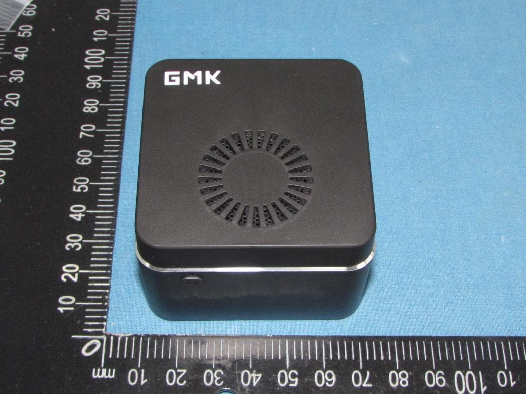
Click to zoom
Application Details
- Equipment Class
- NII - Unlicensed National Information Infrastructure TX
- Date of Grant
- Oct 27, 2020
- Application Purpose
- Original Equipment
- Date of Application
- Oct 27, 2020
- Equipment Note
- NucBox
- Frequency Range
- 5210.00000000 - 5210.00000000
- Country
- China
Documents & Files
Document Text
Text extracted from the exhibit documents filed with the FCC. Open a document above to read the original.
Users Manual
2反面 Technical specifications Note: The pictures listed in this manual are for reference only. Product specifications/button definitions and appearance are subject to change without notice. CPU GPU RAM Storage Ethernet Network Charger Packing list BT WiFi Celeron J4125 14 nm process, 4-core 4-thread, main frequency 2.0Ghz (Max 2.7Ghz), TDP 10W; cache 4MB Intel® Ultra HD Graphics 600 LPDDR4 8GB 128GB/256GB/512GB SSD, M.2 2242, support MicroSD expansion up to 128GB (Product capacity is subject to actual purchase) Support external Ethernet intel AC7265 2X2 AC BT4.2 TYPE-C 12V 2A(DC IN ONLY) 1* mini PC+1* user manual/warranty card +1*TYPE-C charger (Additional: 1* EU/UK /AU adapter) 3正面 Entitled 12-month warranty for the product quality problems caused by non-human factors. Certificate/Inspected Warranty commitment Company: Shenzhen GMK Technology Co., Ltd. Address: 3/F, #5 Bldg, Yifenghua Industrial Park, Huaning Rd, Longhua Dist, 518109, Shenzhen, China 2正面 Please familiarize yourself with the interface and buttons of the device before use. About the Device 1反面 Safety warnings and precautions 3反面 1正面 GMK NUCBOX USER MANUAL Before using and operating this equipment, please read and observe the following precautions carefully to avoid dangerous or illegal operations. Use environment Do not use the device in dusty and humid places to avoid causing internal circuit failures; Do not place this equipment near heating objects such as electric heaters; The working temperature of this equipment is 0-40 degrees, and the normal working temperature is 10-90% RH. Power Please use the special charger that comes standard with this product; Waterproof This device is not waterproof, please keep it dry; Maintenance For all maintenance services, please contact the dealer’ maintenance personnel; Do not insert any sharp objects into the device; Do not drop or bump the device to avoid damage to the device. s FCC Statement This device complies with Part 15 of the FCC Rules. Operation is subject to the following two conditions: (1) this device may not cause harmful interference, and (2) this device must accept any interference received, including interference that may cause undesired operation. changes or modifications not expressly approved by the party responsible for compliance could void the user's authority to operate the equipment. Changes or modifications to this unit not expressly approved by the party responsible for compliance could void the user’s authority to operate the equipment. NOTE: This equipment has been tested and found to comply with the limits for a Class B digital device, pursuant to Part 15 of the FCC Rules. These limits are designed to provide reasonable protection against harmful interference in a residential installation. This equipment generates, uses and can radiate radio frequency energy and, if not installed and used in accordance with the instructions, may cause harmful interference to radio communications. However, there is no guarantee that interference will not occur in a particular installation. If this equipment does cause harmful interference to radio or television reception, which can be determined by turning the equipment off and on, the user is encouraged to try to correct the interference by one or more of the following measures: -- Reorient or relocate the receiving antenna. -- Increase the separation between the equipment and receiver. -- Connect the equipment int o an outle t on a circuit different from that to which the receiver is connected. -- Consult the dealer or an experienced radio/TV techni cian for help. This device and its antenna(s) must not be co-located or operation in conjunction with any other antenna or transmitter. To maintain compliance with FCC’s RF Exposure guidelines, This equipment should be installed and operated with minimum distance of 20cm from your body. The NII band I indoor use only.
Block Diagram
5 5 4 4 3 3 2 2 1 1 DD CC BB AA Intel CPU Gemini Lake BGA1090 Package 24*25*1.44 mm 32.768KHz19.2MHz LPDDR 4 Channel A LPDDR4 Channel B LPDDR4 3G LPDDR4 3G eMMC 5.1 eMMC 128G HDMI-A CONN HDMI OUT SPI BUS 8MB SPI FLASH USB2.0 USB2.0 To TF-SD RTS5170-GR SD TF_SD.Port PCIe/USB2.0 DDI SATA CNVI SATA M.2 SATA SSD WLAN+BT HDA BUS USB2.0+3.0 USB2.0+3.0 EARHPONE JACK ALC269 AUDIO CODEC DC-12V IN TYPE-C CON DC-DC 3.3V DC-DC 5V PMIC RT5077A POWER KEY 3.3V 5V 1.8V USB3.0x1 CON USB3.0x1 CON pwerbuttom 2.4G Title SizeDocument NumberRev Date:Sheetof 2A Block Diagram A3 238Monday, September 07, 2020 GB01 GML_V1.00 Title SizeDocument NumberRev Date:Sheetof 2A Block Diagram A3 238Monday, September 07, 2020 GB01 GML_V1.00 Title SizeDocument NumberRev Date:Sheetof 2A Block Diagram A3 238Monday, September 07, 2020 GB01 GML_V1.00 Bluetooth: 2402 - 2480 MHz WiFi: 2412 - 2480 MHz, 5180 - 5240MHz 5G Product Description:NucBox Model:KB1 FCC ID: 2AXUD-KB1
Cover Letter(s)
CONFIDENTIALITY REQUEST for Certification Service in USA Federal Communication Commission Equipment Authorization Division, Application Processing Branch 7435 Oakland Mills Road Columbia, MD 21046 Date: October 21, 2020 TO WHOM IT MAY CONCERN Pursuant to Paragraphs §0.457 and 0.459 of the Commission’s Rules (47 C.F.R.) and Section §552(b)(4) of the Freedom of Information Act, we requests confidentiality for the following products: FCC ID Model name 2AXUD-KB1 KB1 For the product stated above, we request that the following information be held confidential; Exhibits Long-Term Confidentiality Short-Term Confidentiality Short-Term Confidentiality Days External Photos Internal Photos Block Diagram Schematics Test Setup Photos User’s Manual Parts List Tune Up Operational Descriptions The long-term confidentiality exhibits contain our trade secrets and proprietary information that could be of benefit to our competitors. The short-term confidentiality on the basis of ensuring that business sensitive information remains confidential until the actual marketing of our new device. If you have any questions, please feel free to contact me at the address shown below. Sincerely, Signature Jerome Chung Engineer Shenzhen GMK Technology Co., Ltd
Cover Letter(s)
Shenzhen GMK Technology Co., Ltd 3/F, #5Bldg, HuaLian Industrial Park, XinShi Community, Dalang St, Longhua Dist, 518109, Shenzhen, China Federal Communications Commission Authorization and Evaluation Division Equipment Authorization Branch 7435 Oakland Mills Road Columbia, MD 21046 10/21/2020 To whom it may concern: We, Shenzhen GMK Technology Co., Ltd, the undersigned, hereby authorize Eurofins Product Service GmbH to act on our behalf in all matters relating to applications for equipment authorization FCC ID: 2AXUD-KB1 including the signing of all documents related to these matters. Any and all acts carried out by Eurofins Product Service GmbH on our behalf shall have the same effect as acts of our own. We also hereby certify that no party to this application is subject to a denial of benefits, including FCC benefits, pursuant to Section 5301 of the Anti-Drug Abuse Act of 1988, 21 U.S.C. 862. Sincerely, Signature Jerome Chung Engineer Shenzhen GMK Technology Co., Ltd
Cover Letter(s)
Federal Communication Commission Equipment Authorization Division, Application Processing Branch 7435 Oakland Mills Road Columbia, MD 21046 UNII Device Declaration Letter To whom it may concern: We have declared below featured for FCC equipment authorization, Device FCC ID:2AXUD-KB1 (1) DFS Device: Master Client with Radar detection capability ■ N/A Client without radar detection capability, (2) Active / Passive Scanning , adhoc mode access point capability Frequency Band (MHz) Active Scanning (the device can transmit a probe (beacon)) passive scanning (where the device is can listen only with no probes) Ad Hoc Mode Capability Access point Capability 5180-5240 Yes No Yes No Yes No Yes No 5190-5230 Yes No Yes No Yes No Yes No (3) Country code selection ability Yes No If yes, pls explain how it was implemented: (4) Meet 15.202 requirement Yes No pls check below : A master device is defined as a device operating in a mode in which it has the capability to transmit without receiving an enabling signal. In this mode it is able to select a channel and initiate a network by sending enabling signals to other devices A client device is defined as a device operating in a mode in which the transmissions of the device are under control of the master. A device in client mode is not able to initiate a network. (5) For client devices that have software configuration control to operate in different modes (active scanning in some and passive scanning in others) in different bands (devices with multiple equipment classes or those that operate on non- DFS frequencies) or modular devices which configure the modes of operations through software, the application must provide software and operations description on how the software and / or hardware is implemented to ensure that proper operations modes cannot be modified by end user or an installer. Apply Does not apply (If apply, pls help to provide explanation on it was implement, and how software was controlled) Sincerely, Signature Jerome Chung Engineer Shenzhen GMK Technology Co., Ltd
External Photos
Shenzhen Tongzhou Testing Co.,Ltd FCC ID: 2AXUD-KB1 This reportshall not be reproduced except in full, without the written approval of Shenzhen Shenzhen Tongzhou Testing Co.,Ltd Page 1 of 4 EXTERIOR PHOTOGRAPHS OF EUT Fig.1 Fig.2 Shenzhen Tongzhou Testing Co.,Ltd FCC ID: 2AXUD-KB1 This reportshall not be reproduced except in full, without the written approval of Shenzhen Shenzhen Tongzhou Testing Co.,Ltd Page 2 of 4 Fig.3 Fig.4 Shenzhen Tongzhou Testing Co.,Ltd FCC ID: 2AXUD-KB1 This reportshall not be reproduced except in full, without the written approval of Shenzhen Shenzhen Tongzhou Testing Co.,Ltd Page 3 of 4 Fig.5 Fig.6 Shenzhen Tongzhou Testing Co.,Ltd FCC ID: 2AXUD-KB1 This reportshall not be reproduced except in full, without the written approval of Shenzhen Shenzhen Tongzhou Testing Co.,Ltd Page 4 of 4 Fig.7 Fig.8
ID Label/Location Info
Label & Label Location Size:35mm(L)*30mm(W) FCC ID: 2AXUD-KB1 This device complies with Part 15 of the FCC Rules. Operation is subject to the following two conditions: (1) this device may not cause harmful interference, and (2) this device must accept any interference received, including interference that may cause undesired operation.
Internal Photos
Shenzhen Tongzhou Testing Co.,Ltd FCC ID: 2AXUD-KB1 This report shall not be reproduced except in full, without the written approval of Shenzhen Tongzhou Testing Co.,Ltd Page 1 of 8 INTERIOR PHOTOGRAPHS OF EUT Fig.1 Fig.2 Shenzhen Tongzhou Testing Co.,Ltd FCC ID: 2AXUD-KB1 This report shall not be reproduced except in full, without the written approval of Shenzhen Tongzhou Testing Co.,Ltd Page 2 of 8 Fig.3 Fig.4 Shenzhen Tongzhou Testing Co.,Ltd FCC ID: 2AXUD-KB1 This report shall not be reproduced except in full, without the written approval of Shenzhen Tongzhou Testing Co.,Ltd Page 3 of 8 Fig.5 Fig.6 Shenzhen Tongzhou Testing Co.,Ltd FCC ID: 2AXUD-KB1 This report shall not be reproduced except in full, without the written approval of Shenzhen Tongzhou Testing Co.,Ltd Page 4 of 8 Fig.7 Fig.8 Bluetooth Antenna WIFI Antenna Shenzhen Tongzhou Testing Co.,Ltd FCC ID: 2AXUD-KB1 This report shall not be reproduced except in full, without the written approval of Shenzhen Tongzhou Testing Co.,Ltd Page 5 of 8 Fig.8 Fig.9 Shenzhen Tongzhou Testing Co.,Ltd FCC ID: 2AXUD-KB1 This report shall not be reproduced except in full, without the written approval of Shenzhen Tongzhou Testing Co.,Ltd Page 6 of 8 Fig.10 Fig.11 Shenzhen Tongzhou Testing Co.,Ltd FCC ID: 2AXUD-KB1 This report shall not be reproduced except in full, without the written approval of Shenzhen Tongzhou Testing Co.,Ltd Page 7 of 8 Fig.12 Fig.13 Shenzhen Tongzhou Testing Co.,Ltd FCC ID: 2AXUD-KB1 This report shall not be reproduced except in full, without the written approval of Shenzhen Tongzhou Testing Co.,Ltd Page 8 of 8 Fig.14
RF Exposure Info
Shenzhen Tongzhou Testing Co.,Ltd FCC ID: 2AXUD-KB1 This report shall not be reproduced except in full, without the written approval of Shenzhen Shenzhen Tongzhou Testing Co.,Ltd Page 1 of 7 Maximum Permissible Exposure Report Product Information EUT : NucBox Model Number : KB1 Model Declaration : N/A Test Model : KB1 Power Supply : DC 12V by adapter Hardware version : GB01_MB_V300 Software version : Windows 10 Sample ID : TZ200901687–1# Bluetooth Bluetooth Version : V4.2+EDR Channel Number : 79 Channels for Bluetooth BR/EDR(DSS) 40 Channels for BLE (DTS) Modulation Technology : GFSK, π/4-DQPSK, 8-DPSK for Bluetooth BR/EDR (DSS) GFSK for BLE (DTS) Data Rates : Bluetooth BR/EDR (DSS): 1/2/3Mbps BLE (DTS): 1Mbps Antenna Type And Gain Internal Antenna /1.41 dBi(Max.) WiFi WLAN : Supported IEEE 802.11a/b/g/n WLAN FCC Operation Frequency : IEEE 802.11b:2412-2462MHz IEEE 802.11g:2412-2462MHz IEEE 802.11n HT20:2412-2462MHz / 5180-5240MHz IEEE 802.11n HT40:2422-2452MHz / 5190-5230MHz IEEE 802.11a: 5180-5240MHz WLAN Channel Number : 11 Channels for 2412-2462MHz(IEEE 802.11b/g/n HT20) 7 Channels for 2422-2452MHz(IEEE 802.11n HT40) 4 Channels for 5180-5240MHz (IEEE 802.11a/n HT20) 2 Channels for 5190-5230MHz (IEEE 802.11n HT40) WLAN Modulation Technology : IEEE 802.11b: DSSS(CCK,DQPSK,DBPSK) IEEE 802.11g: OFDM (64QAM, 16QAM, QPSK, BPSK) IEEE 802.11n: OFDM (64QAM, 16QAM, QPSK, BPSK) IEEE 802.11a: OFDM (64QAM, 16QAM, QPSK, BPSK) Antenna Type And Gain : Internal Antenna Wlan2.4G: 1.41 dBi(Max.) Wlan5G:1.49 dBi(Max.) Note: Antenna position refer to EUT Photos. 2. Evaluation Method Systems operating under the provisions of FCC 47 CFR section shall be operated in a manner that ensures that the public is not exposed to radio frequency energy level in excess of the Commission’s guidelines. In accordance with 47 CFR FCC Part 2 Subpart J, section 2.1091 this device has been defined as mobile device whereby a distance of 0.2m normally can be maintained between the user and the device, and below RF Permissible Exposure limit shall comply with. In accordance with KDB447498D01 for Simultaneous transmission MPE test exclusion applies when the sum of the MPE ratios for all simultaneous transmitting antennas incorporated in a host device, based on the Shenzhen Tongzhou Testing Co.,Ltd FCC ID: 2AXUD-KB1 This report shall not be reproduced except in full, without the written approval of Shenzhen Shenzhen Tongzhou Testing Co.,Ltd Page 2 of 7 calculated/estimated, numerically modelled or measured field strengths or power density, is ≤ 1.0. The MPE ratio of each antenna is determined at the minimum test separation distance required by the operating configurations and exposure conditions of the host device, according to the ratio of field strengths or power density to MPE limit, at the test frequency. Either the maximum peak or spatially averaged results from measurements or numerical simulations may be used to determine the MPE ratios. Spatial averaging does not apply when MPE is estimated using simple calculations based on far-field plane-wave equivalent conditions. The antenna installation and operating requirements for the host device must meet the minimum test separation distances required by all antennas, in both standalone and simultaneous transmission operations, to satisfy compliance. 3. Limit 3. 1 Refer evaluation method ANSI C95.1–1999: IEEE Standard for Safety Levels with Respect to Human Exposure to Radio Frequency Electromagnetic Fields, 3 kHz to 300 GHz. FCC KDB publication 447498 D01 General 1 RF Exposure Guidance v06: Mobile and Portable Devices RF Exposure Procedures and Equipment Authorization Policies. FCC CFR 47 part1 1.1310: Radiofrequency radiation exposure limits. FCC CFR 47 part2 2.1091: Radiofrequency radiation exposure evaluation: mobile devices Shenzhen Tongzhou Testing Co.,Ltd FCC ID: 2AXUD-KB1 This report shall not be reproduced except in full, without the written approval of Shenzhen Shenzhen Tongzhou Testing Co.,Ltd Page 3 of 7 3. 2 Limit Limits for Maximum Permissible Exposure (MPE)/Controlled Exposure Frequency Range(MHz) Electric Field Strength(V/m) Magnetic Field Strength(A/m) Power Density (mW/cm²) Averaging Time (minute) Limits for Occupational/Controlled Exposure 0.3 – 3.0 3.0 – 30 30 – 300 300 – 1500 1500 – 100,000 614 1842/f 61.4 / / 1.63 4.89/f 0.163 / / (100) * (900/f 2 )* 1.0 f/300 5 6 6 6 6 6 Limits for Maximum Permissible Exposure (MPE)/Uncontrolled Exposure Frequency Range(MHz) Electric Field Strength(V/m) Magnetic Field Strength(A/m) Power Density (mW/cm²) Averaging Time (minute) Limits for Occupational/Controlled Exposure 0.3 – 3.0 3.0 – 30 30 – 300 300 – 1500 1500 – 100,000 614 824/f 27.5 / / 1.63 2.19/f 0.073 / / (100) * (180/f 2 )* 0.2 f/1500 1.0 30 30 30 30 30 F=frequency in MHz *=Plane-wave equivalent power density 4. MPE Calculation Method Predication of MPE limit at a given distance Equation from page 18 of OET Bulletin 65, Edition 97-01 S=PG/4πR² Where: S=power density P=power input to antenna G=power gain of the antenna in the direction of interest relative to an isotropic radiator R=distance to the center of radiation of the antenna 5. Antenna Information This Product can only use antennas certificated as follows provided by manufacturer; Antenna Gain and type refer to Product information Shenzhen Tongzhou Testing Co.,Ltd FCC ID: 2AXUD-KB1 This report shall not be reproduced except in full, without the written approval of Shenzhen Shenzhen Tongzhou Testing Co.,Ltd Page 4 of 7 6. Conducted Power 2.4G Band: Bluetooth(BDR+EDR) Test Mode Channel Frequency (MHz) Measured Peak Output Power (dBm) GFSK 00 2402 11.33 39 2441 10.67 78 2480 11.54 π/4-DQPSK 00 2402 10.62 39 2441 10.1 78 2480 11.26 8-DPSK 00 2402 10.64 39 2441 10.12 78 2480 11.25 Bluetooth(BLE) Test Mode Channel Frequency (MHz) Measured Peak Output Power (dBm) GFSK 00 2402 -1.16 19 2440 -1.03 39 2480 -0.9 WiFi 2.4GHz Band Test Mode Channel Frequency (MHz) Measured Peak Output Power (dBm) IEEE 802.11b 1 2412 1…
Text truncated - open the document above for the full version.
Test Report
Report No.: TZ200901687-E4 Page 1 of 70 FCC TEST REPORT Test report On Behalf of Shenzhen GMK Technology Co., Ltd For NucBox Model No.: KB1 FCC ID: 2AXUD-KB1 Prepared for : Shenzhen GMK Technology Co., Ltd 3/F, #5Bldg, HuaLian Industrial Park, XinShi Community, Dalang St, Longhua Dist, 518109, Shenzhen, China Prepared By : Shenzhen Tongzhou Testing Co.,Ltd 1th Floor, Building 1, Haomai High-tech Park, Huating Road 387, Dalang Street, Longhua, Shenzhen, China Date of Test: 2020/9/22 ~ 2020/10/13 Date of Report: 2020/10/13 Report Number: TZ200901687-E4 The test report apply only to the specific sample(s) tested under stated test conditions It is not permitted to copy extracts of these test result without the written permission of the test laboratory. Report No.: TZ200901687-E4 Page 2 of 70 TEST RESULT CERTIFICATION Applicant’s name ................. : Shenzhen GMK Technology Co., Ltd Address .................................. : 3/F, #5Bldg, HuaLian Industrial Park, XinShi Community, Dalang St, Longhua Dist, 518109, Shenzhen, China Manufacture's Name ............ : Shenzhen GMK Technology Co., Ltd Address .................................. : 3/F, #5Bldg, HuaLian Industrial Park, XinShi Community, Dalang St, Longhua Dist, 518109, Shenzhen, China Product description Trade Mark ................................ : GMK Product name ............................ : NucBox Model and/or type reference : KB1 Standards.............................. : FCC Rules and Regulations Part 15 Subpart E Section 15.407 ANSI C63.10: 2013 This publication may be reproduced in whole or in part for non-commercial purposes as long as the Shenzhen Tongzhou Testing Co.,Ltd is acknowledged as copyright owner and source of the material. Shenzhen Tongzhou Testing Co.,Ltd takes no responsibility for and will not assume liability for damages resulting from the reader's interpretation of the reproduced material due to its placement and context. Date of Test ........................................... : Date (s) of performance of tests ............. : 2020/9/22 ~ 2020/10/13 Date of Issue .......................................... : 2020/10/13 Test Result .............................................. : Pass Testing Engineer : (Anna Hu) Technical Manager : (Hugo Chen) Authorized Signatory : (Andy Zhang) Report No.: TZ200901687-E4 Page 3 of 70 Revision History Revision Issue Date Revisions Revised By 000 2020/10/13 Initial Issue Andy Zhang Report No.: TZ200901687-E4 Page 4 of 70 TABLE OF CONTENTS 1. GENERAL INFORMATION ................................................................................................................................... 5 1.1. DESCRIPTION OF DEVICE (EUT) ........................................................................................................................ 5 1.2 EUT CONFIGURATION .......................................................................................................................................... 6 1.3. EXTERNAL I/O CABLE ......................................................................................................................................... 6 1.4. DESCRIPTION OF TEST FACILITY ........................................................................................................................ 6 1.5. STATEMENT OF THE MEASUREMENT UNCERTAINTY .......................................................................................... 7 1.6. MEASUREMENT UNCERTAINTY ........................................................................................................................... 7 1.7. DESCRIPTION OF TEST MODES .......................................................................................................................... 7 2. TEST METHODOLOGY ......................................................................................................................................... 8 2.1. EUT CONFIGURATION......................................................................................................................................... 8 2.2. EUT EXERCISE ................................................................................................................................................... 8 2.3. GENERAL TEST PROCEDURES ........................................................................................................................... 8 3. SYSTEM TEST CONFIGURATION ...................................................................................................................... 9 3.1. JUSTIFICATION..................................................................................................................................................... 9 3.2. EUT EXERCISE SOFTWARE ................................................................................................................................ 9 3.3. SPECIAL ACCESSORIES ...................................................................................................................................... 9 3.4. BLOCK DIAGRAM/SCHEMATICS........................................................................................................................... 9 3.5. EQUIPMENT MODIFICATIONS .............................................................................................................................. 9 3.6. TEST SETUP ........................................................................................................................................................ 9 4. SUMMARY OF TEST RESULTS ........................................................................................................................ 10 5. TEST RESULT ....................................................................................................................................................... 11 5.1. ON TIME AND DUTY CYCLE .............................................................................................................................. 11 5.2. M…
Text truncated - open the document above for the full version.
Test Report
Report No.: TZ200901687-E4 Page 38 of 70 5.5. Radiated Emissions Measurement 5.5.1. Standard Applicable 15.205 (a) Except as shown in paragraph (d) of this section, only spurious emissions are permitted in any of the frequency bands listed below: MHz MHz MHz GHz 0.090-0.110 \1\ 0.495-0.505 2.1735-2.1905 4.125-4.128 4.17725-4.17775 4.20725-4.20775 6.215-6.218 6.26775-6.26825 6.31175-6.31225 8.291-8.294 8.362-8.366 8.37625-8.38675 8.41425-8.41475 12.29-12.293. 12.51975-12.52025 12.57675-12.57725 13.36-13.41 16.42-16.423 16.69475-16.69525 16.80425-16.80475 25.5-25.67 37.5-38.25 73-74.6 74.8-75.2 108-121.94 123-138 149.9-150.05 156.52475-156.52525 156.7-156.9 162.0125-167.17 167.72-173.2 240-285 322-335.4 399.9-410 608-614 960-1240 1300-1427 1435-1626.5 1645.5-1646.5 1660-1710 1718.8-1722.2 2200-2300 2310-2390 2483.5-2500 2690-2900 3260-3267 3332-3339 3345.8-3358 3600-4400 4.5-5.15 5.35-5.46 7.25-7.75 8.025-8.5 9.0-9.2 9.3-9.5 10.6-12.7 13.25-13.4 14.47-14.5 15.35-16.2 17.7-21.4 22.01-23.12 23.6-24.0 31.2-31.8 36.43-36.5 (\2\) \1\ Until February 1, 1999, this restricted band shall be 0.490-0.510 MHz. \2\ Above 38.6 For transmitters operating in the 5.15-5.25 GHz band: All emissions outside of the 5.15-5.35 GHz band shall not exceed an e.i.r.p. of −27 dBm/MHz (68.2dBuV/m at 3m). In addition, In case the emission fall within the restricted band specified on 15.205(a), then the 15.209(a) limit in the table below has to be followed. Frequencies (MHz) Field Strength (microvolts/meter) Measurement Distance (meters) 0.009~0.490 2400/F(KHz) 300 0.490~1.705 24000/F(KHz) 30 1.705~30.0 30 30 30~88 100 3 88~216 150 3 216~960 200 3 Above 960 500 3 5.5.2. Measuring Instruments and Setting Please refer to section 6 of equipment list in this report. The following table is the setting of spectrum analyzer and receiver. Spectrum Parameter Setting Attenuation Auto Start Frequency 1000 MHz Stop Frequency 10 th carrier harmonic RB / VB (Emission in restricted band) 1MHz / 1MHz for Peak, 1 MHz / 1/B kHz for Average RB / VB (Emission in non-restricted band) 1MHz / 1MHz for Peak, 1 MHz / 1/B kHz for Average Receiver Parameter Setting Attenuation Auto Start ~ Stop Frequency 9kHz~150kHz / RB/VB 200Hz/1KHz for QP/AVG Start ~ Stop Frequency 150kHz~30MHz / RB/VB 9kHz/30KHz for QP/AVG Start ~ Stop Frequency 30MHz~1000MHz / RB/VB 120kHz/1MHz for QP Report No.: TZ200901687-E4 Page 39 of 70 5.5.3. Test Procedures 1) Sequence of testing 9 kHz to 30 MHz Setup: --- The equipment was set up to simulate a typical usage like described in the user manual or described by manufacturer. --- If the EUT is a tabletop system, a rotatable table with 0.8 m height is used. --- If the EUT is a floor standing device, it is placed on the ground. --- Auxiliary equipment and cables were positioned to simulate normal operation conditions. --- The AC power port of the EUT (if available) is connected to a power outlet below the turntable. --- The measurement distance is 3 meter. --- The EUT was set into operation. Premeasurement: --- The turntable rotates from 0° to 315° using 45° steps. --- The antenna height is 1.5 meter. --- At each turntable position the analyzer sweeps with peak detection to find the maximum of all emissions Final measurement: --- Identified emissions during the premeasurement the software maximizes by rotating the turntable position (0° to 360°) and by rotating the elevation axes (0° to 360°). --- The final measurement will be done in the position (turntable and elevation) causing the highest emissions with QPK detector. --- The final levels, frequency, measuring time, bandwidth, turntable position, correction factor, margin to the limit and limit will be recorded. Also a plot with the graph of the premeasurement and the limit will be stored. Report No.: TZ200901687-E4 Page 40 of 70 2) Sequence of testing 30 MHz to 1 GHz Setup: --- The equipment was set up to simulate a typical usage like described in the user manual or described by manufacturer. --- If the EUT is a tabletop system, a table with 0.8 m height is used, which is placed on the ground plane. --- If the EUT is a floor standing device, it is placed on the ground plane with insulation between both. --- Auxiliary equipment and cables were positioned to simulate normal operation conditions --- The AC power port of the EUT (if available) is connected to a power outlet below the turntable. --- The measurement distance is 3 meter. --- The EUT was set into operation. Premeasurement: --- The turntable rotates from 0° to 315° using 45° steps. --- The antenna is polarized vertical and horizontal. --- The antenna height changes from 1 to 3 meter. --- At each turntable position, antenna polarization and height the analyzer sweeps three times in peak to find the maximum of all emissions. Final measurement: --- The final measurement will be performed with minimum the six highest peaks. --- According to the maximum antenna and turntable positions of premeasurement the software maximize the peaks by changing turntable position (± 45°) and antenna movement between 1 and 4 meter. --- The final measurement will be done with QP detector with an EMI receiver. --- The final levels, frequency, measuring time, bandwidth, antenna height, antenna polarization, turntable angle, correction factor, margin to the limit and limit will be recorded. Also a plot with the graph of the premeasurement with marked maximum final measurements and the limit will be stored. Report No.: TZ200901687-E4 Page 41 of 70 3) Sequence of testing 1 GHz to 18 GHz Setup: --- The equipment was set up to simulate a typical usage like described in the user manual or described by manufacturer. --- If the EUT is a tabletop system, a rotatable table with 1.5 m height is used. --- If the EUT is a floor standing device, it is placed on the ground plane with insulation between both. --- Auxiliary equipment and cables were positioned to simulate normal operation conditions --- The AC power port of the EUT (if available) is conn…
Text truncated - open the document above for the full version.
Test Setup Photos
Shenzhen Tongzhou Testing Co.,Ltd FCC ID: …
Text truncated - open the document above for the full version.
Contact Information
Applicant
Jerome Chung
Test Firm
Shenzhen Tongzhou Testing Co., LTDAndy Zhang
[email protected]+86-755-32902198
Technical Specifications
| # | Rule Parts | Frequency Range | Power Output |
|---|---|---|---|
| 3 | 15E | 5.21 GHz - 5.21 GHz | 17.00 mW |
Other Applications from Shenzhen GMK Technology Co., Ltd
2AXUD-G3S
Apr 10, 2026Mini PC
Equipment Class
DSS - Part 15 Spread Spectrum Transmitter2AXUD-M6ULTRA
Sep 04, 2025Mini PC
2AXUD-G1
May 05, 2023NucBox
Equipment Class
NII - Unlicensed National Information Infrastructure TX
2AXUD-KB5
Apr 28, 2022NucBox5
Equipment Class
DSS - Part 15 Spread Spectrum Transmitter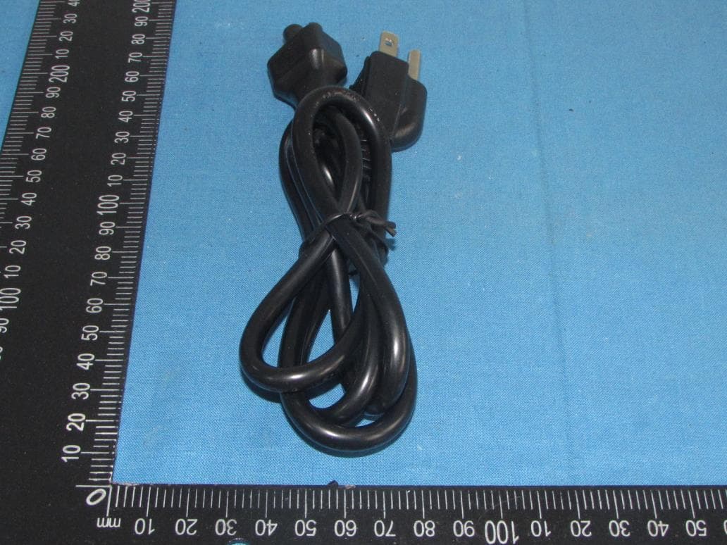
2AXUD-KB2
Apr 13, 2021NucBox2
Equipment Class
DSS - Part 15 Spread Spectrum Transmitter