Text extracted from the exhibit documents filed with the FCC. Open a document above to read the original.
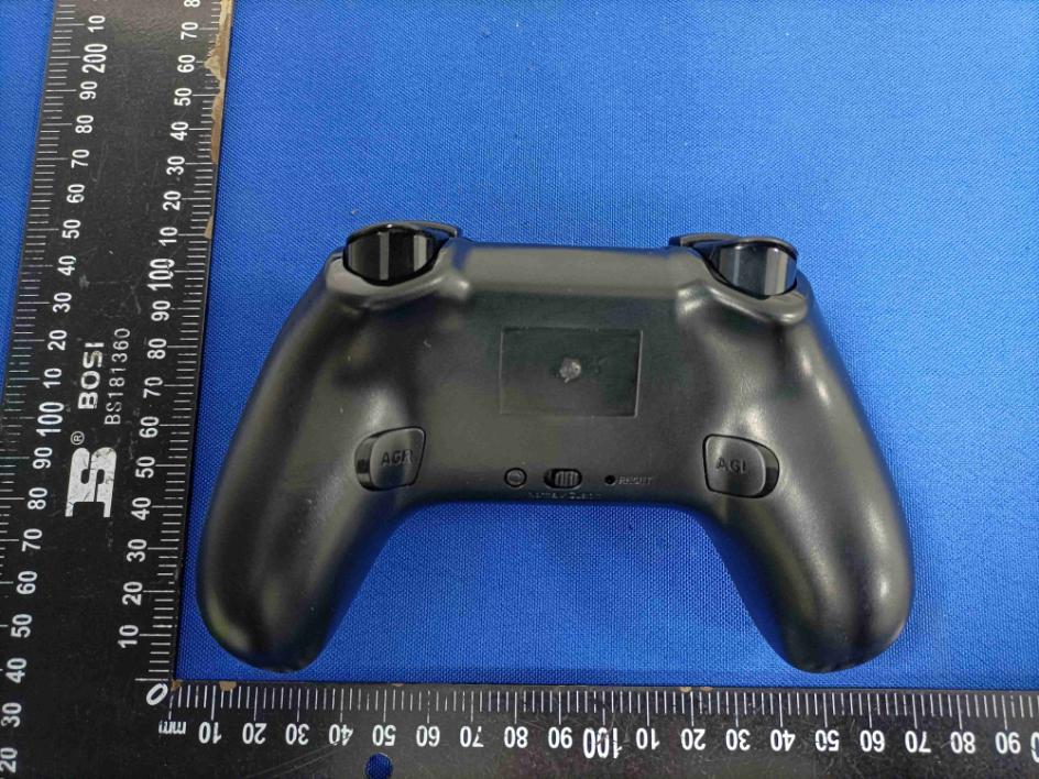
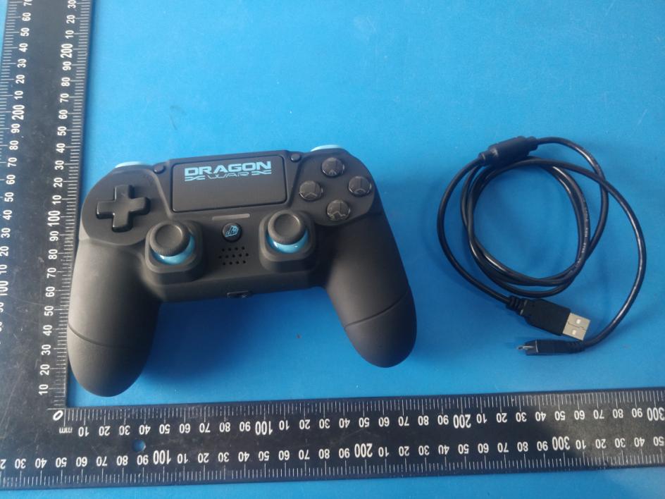
WirelessGame Controller Manual Here’s the new Dragon Shock 4 Bluetooth Wireless Controller in its 5th Edition, design for PlayStation 4 console. This controller is compatible with PlayStation 4 Bluetooth Wireless specifications, corresponding to 4 analog axis, 2 analog keys and 16 digitals buttons, RGB LED ,4 atomic buttons and 3D with LED underneath, Big and Small Vibration, 6-axis Motion Sensor, Headset jack port, Wireless pairing function. Compatible with the new DualShock 4 wireless controller (CUH-ZCT 2 series). SAFETY INSTRUCTIONS Please do not store the product in a humid or high-temperature place Don't knock, beat, drub, pierce or try to decompose the gamepad to avoid unnecessary damage to the gamepad. Built-in battery, please do NOT throw this product in the trash Do not charge the controller near fire or other heat source Non-professionals should not disassemble this product, otherwise it is not be eligible to after-sales warranty service If the controller cannot turn on, please fully charge it PRODUCT FEATURE Compatible with all button functions, NO touch function, motor corresponding functions, With sensor function . Includes RGB LED function,3 blue LEDs and 4 atomic buttons under the left and right joysticks correspond to LED of different colors. Includes 16 buttons function input keys. Built-in twin motors, High precision 3D rocker. Sensitive button response, easy to use. Support PlayStation 3 console.(By micro–USB cable). Support Bluetooth wireless(Bluetooth 5.0). Support USB wired pairing (USB 1.1 or USB 2.0, micro USB B). 01 SHARE Button10 Left analog joystick/L3 button with blue 02 Touch pad button-NO touch functionbacklight-Press down on the stick to use 03 Option buttonit as the L3 button 04 Directional buttons11 PS button 05 Triangle Button with green backlight 12 Right analog joystick/R3 button with 06 Square Button with pink backlightblue backlight-Press down on the stick 07 Circle Button with red backlightto use it as the R3 button 08 Cross Button with blue backlight13 Speaker 09 RGB LED 14 R1 button 15 R2 trigger 16 USB pprt 17 L1 button 18 L2 trigger 19 RESET button 20 Headset jack port PAIRING PROCESS 1 Connect the Dragon Shock 4 controller to the PlayStation 4 console with the micro–USB cable provided. 2 After pairing is complete, please press the PS button to activate wireless connection. 3 Dragon Shock 4 controllers can be paired to a PlayStation 4 at the same time. PlayStation 4 can recognize up to 32 different paired controllers. Press the PS button to take the console out of its Sleep Mode UPDATE FOR THE GAMEPAD 1. Open the firmware update, as indicated below. Note: The following upgrade tools may differ with the picture, but the operation method stays the same. 2.When the Dragon Shock 4 is in standby mode, long press the SHARE and Cross buttons and connect the gamepad to the computer with the micro-USB cable provided. The controller driver will enter in update mode. Then select DOWNLOAD to launch the update. Refer to the second image below to see if the update was successful. FUNCTIONS (Sorted regarding product plan ) NumberNameFunction 1SHARE ButtonSHARE functions (printscreen, recording video, ...) 2 Touchpad button action button - activates an in-game command (depending on the game settings) 3 OPTION ButtonOPTION button / in-game pause button 4 Directional buttons 8-position directional action button - activates in-game commands (depending on game's settings) 5Triangle Button action button - activates an in-game command (depending on game's settings) 6Square Button action button - activates an in-game command (depending on game's settings) 7Circle Button action button - activates an in-game command (depending on game's settings) 8Cross Button action button - activates an in-game command (depending on game's settings) 9 Touch pad light bar Power indicator / in-game light bar status indicator (depending on game's settings) 10 Left analog joystick / L3 button Directionnal joystick / action button - activates an in-game command when pressed down (depending on game's settings) 11PS Button Controller power button / exit console sleep mode / back to console's main menu 12 Right analog joystick / R3 button Directionnal joystick / action button - activates an in-game command when pressed down(depending on game's settings) 14R1 button action button - activates an in-game command (depending on game's settings) 15 R2trigger button action button - activates an in-game command (depending on game's settings) 17L1 button action button - activates an in-game command (depending on game's settings) 18 L2trigger button action button - activates an in-game command (depending on game's settings) 19RESET buttonallows to reset the controller SPECIAL FEATURES PS button: display the console’s main screen (when PlayStation 4 console power is on), allow to exit console’s sleep mode and to switch between applications during launch; press long PS button allows to enter settings menu SHARE button: open the SHARE menu to select options available as printscreen, recording a in-game video, etc. OPTION button: opens in-game options/main menu or pause the game (depending on game’s settings) This product does not support PS VITATV. RGB DISPLAY Colorful RGB LED: To display the player’s status, press the PS button and the light bar will turn on the light of the corresponding player as: Player one: Blue / Player two: Red / Player three: Green / Player four: pink A. During pairing, the light bar will flash in white and, after connection, will light in solid blue B. During charging mode with the controller off, the light bar will illuminate orange in slow pulses. C. During charging mode with the controller on, the light bar will illuminate solid blue. ELECTRIC ALIMENTATION INFORMATION 1 Operating voltage: DC3.6v -- 4.2V 2 Operating current without vibration: less than 100mA 3 Operating time in constant use: about 4 hours 4 Standby current: less than 10mA 5 Charging voltage/cu…
Text truncated - open the document above for the full version.
Differences Description We&/''LVWULEXWLRQ6$state: )&&,'$<*636 3URGXFW1DPH:LUHOHVV*DPH&RQWUROOHU Model: *636%.*636:+*636%/*6365' All model’s the software and electric circuit are the same, only with theDSSHDUDQFHFRORUDQGmodel name different. 6LJQDWXUH 1DPH-HQQ\7VH 3RVLWLRQ0DQDJHU &RPSDQ\1DPH &/''LVWULEXWLRQ6$ $GGUHVV 5XHGX*UDQG&KDPS)HUQHOPRQW%HOJLXP 7HO )D[ (PDLOMHQQ\WVH#ZHJDKNFRP
CLD Distribution S.A. March 10, 2021 Equipment Autorisation Division Federal Communications Commission 7435 Oakland Mills Road Columbia, MD 21046 FCC ID: 2AY59-GSPS4 Product Name: Wireless Game Controller Request for Confidentiality Pursuant to Sections 0.457 and 0.459 of the commissions rules, we hereby request that the following documents be held confidential: Schematics Long-term confidential Block diagram Long-term confidential Operation description Long-term confidential These materials contain trade secrets and proprietary information and are not customarily released to the public. The public disclosure of this information might be harmful to the company and provide unjustified benefits to our competitors. Signature: Name Jenny Tse Position Manager Company Name CLD Distribution S.A. Address Rue du Grand Champ 14, 5380 Fernelmont, Belgium Tel +85266231642 Fax / Email [email protected]
FCC ID: 2AY59-GSPS4 FCC ID: 2AY59-GSPS4 FCC ID: 2AY59-GSPS4 FCC ID: 2AY59-GSPS4
5cm 1.5cm Label Location FCC ID: 2AY59-GSPS4 CLD Distribution S.A. Model name: Wireless Game Controller Model No.: GSPS4-BK
FCC ID: 2AY59-GSPS4 FCC ID: 2AY59-GSPS4 FCC ID: 2AY59-GSPS4 Antenna
FCC ID: 2AY59-GSPS4 RF Exposure evaluation According to 447498 D01 General RF Exposure Guidance v06 The 1-g and 10-g SAR test exclusion thresholds for 100 MHz to 6 GHz at test separation distances ≤ 50 mm are determined by: [(max. power of channel, including tune-up tolerance, mW)/(min. test separation distance, mm)] ·[√f(GHz)] ≤ 3.0 for 1-g SAR and ≤ 7.5 for 10-g extremity SAR, where f(GHz) is the RF channel transmit frequency in GHz Power and distance are rounded to the nearest mW and mm before calculation The result is rounded to one decimal place for comparison Worse case is as below: [2480MHz: 5.06dBm (3.21mW) output power] (3.21mW /5mm)·[√2.480(GHz)]= 1.01<3.0 for 1-g SAR Then SAR evaluation is not required
FCC TEST REPORT FCC ID: 2AY59-GSPS4 On Behalf of CLD Distribution S.A. Wireless Game Controller Model No.: GSPS4-BK, GSPS4-WH, GSPS4-BL, GSPS4-RD Prepared for : CLD Distribution S.A. Address : Rue du Grand Champ 14, 5380 Fernelmont, Belgium Prepared By : Shenzhen Alpha Product Testing Co., Ltd. Address : Building i, No.2, Lixin Road, Fuyong Street, Bao’an District, 518103, Shenzhen, Guangdong, China Report Number : A2101045-C01-R02 Date of Receipt : January 28, 2021 Date of Test : January 28, 2021 – March 02, 2021 Date of Report : March 02, 2021 Version Number : V0 Page 2 of 31 Report No.: A2101045-C01-R02 TABLE OF CONTENTS Description Page 1. Summary Of Standards And Results ---------------------------------------------------------------- 6 1.1. Description of Standards and Results ---------------------------------------------------------- 6 2. General Information ------------------------------------------------------------------------------------ 7 2.1. Description of Device (EUT) -------------------------------------------------------------------- 7 2.2. Accessories of Device (EUT) ------------------------------------------------------------------- 8 2.3. Tested Supporting System Details -------------------------------------------------------------- 8 2.4. Block Diagram of connection between EUT and simulators ------------------------------- 8 2.5. Test Mode Description --------------------------------------------------------------------------- 8 2.6. Test Conditions ------------------------------------------------------------------------------------ 8 2.7. Test Facility ---------------------------------------------------------------------------------------- 9 2.8. Measurement Uncertainty ----------------------------------------------------------------------- 9 2.9. Test Equipment List ---------------------------------------------------------------------------- 10 3. Spurious Emission --------------------------------------------------------------------------------------11 3.1. Test Limits --------------------------------------------------------------------------------------- 11 3.2. Test Procedure ----------------------------------------------------------------------------------- 11 3.3. Test Setup ---------------------------------------------------------------------------------------- 12 3.4. Test Results -------------------------------------------------------------------------------------- 13 4. Power Line Conducted Emission ------------------------------------------------------------------- 16 4.1. Test Limits --------------------------------------------------------------------------------------- 16 4.2. Test Procedure ----------------------------------------------------------------------------------- 16 4.3. Test Setup ---------------------------------------------------------------------------------------- 16 4.4. Test Results -------------------------------------------------------------------------------------- 16 5. Conducted Maximum Output Power ------------------------------------------------------------- 18 5.1. Test limits ---------------------------------------------------------------------------------------- 18 5.2. Test Procedure ----------------------------------------------------------------------------------- 18 5.3. Test Setup ---------------------------------------------------------------------------------------- 18 5.4. Test Results -------------------------------------------------------------------------------------- 18 6. Power Spectral Density ------------------------------------------------------------------------------- 19 6.1. Test limits ---------------------------------------------------------------------------------------- 19 6.2. Test Procedure ----------------------------------------------------------------------------------- 19 6.3. Test Setup ---------------------------------------------------------------------------------------- 19 6.4. Test Results -------------------------------------------------------------------------------------- 19 7. Bandwidth ----------------------------------------------------------------------------------------------- 20 7.1. Test limits ---------------------------------------------------------------------------------------- 21 7.2. Test Procedure ----------------------------------------------------------------------------------- 21 7.3. Test Setup ---------------------------------------------------------------------------------------- 21 7.4. Test Results -------------------------------------------------------------------------------------- 21 8. Band Edge Check -------------------------------------------------------------------------------------- 24 8.1. Test limits ---------------------------------------------------------------------------------------- 24 8.2. Test Procedure ----------------------------------------------------------------------------------- 24 8.3. Test Setup ---------------------------------------------------------------------------------------- 24 8.4. Test Results -------------------------------------------------------------------------------------- 24 9. Antenna Requirement -------------------------------------------------------------------------------- 28 9.1. Standard Requirement -------------------------------------------------------------------------- 28 9.2. Antenna Connected Construction ------------------------------------------------------------- 28 Page 3 of 31 Report No.: A2101045-C01-R02 9.3. Results -------------------------------------------------------------------------------------------- 28 10. Test Setup Photo --------------------------------------------------------------------------------------- 29 11. Photographs Of The EUT ---------------------------------------------------------------------------- 31 Page 4 of 31 Report No.: A2101045-C01-R02 TEST REPORT DECLARATION Applicant : CLD Distribution S.A. Address : Rue du Grand Champ 14, 5380 Fernelmont, Belgium Manufacturer : Shenzhen CHT…
Text truncated - open the document above for the full version.
FCC ID: 2AY59-GSPS4 Photos of Radiated Emission Test (In Semi Anechoic Chamber 30MHz~1GHz) Photos of Radiated Emission Test (In Semi Anechoic Chamber above 1GHz) FCC ID: 2AY59-GSPS4 Photos of Conducted disturbance at mains terminals test
| # | Rule Parts | Frequency Range | Power Output |
|---|---|---|---|
| 1 | 15C | 2.40 GHz - 2.48 GHz | 2.84 mW |

WIRELESS CONTROLLER
Equipment Class
DSS - Part 15 Spread Spectrum Transmitter