2AYBY-W04Digital microscope
Shenzhen Microlong Technology Co.,Ltd
Click to zoom
Application Details
- Equipment Class
- DTS - Digital Transmission System
- Date of Grant
- Dec 17, 2020
- Application Purpose
- Original Equipment
- Date of Application
- Dec 17, 2020
- Equipment Note
- Digital microscope
- Frequency Range
- 2412.00000000 - 2462.00000000
- Country
- China
Documents & Files
Document Text
Text extracted from the exhibit documents filed with the FCC. Open a document above to read the original.
Users Manual
1 / 7 W04-Wifi Digital Microscope (for IOS/Android) Quick Start Guide Version V0.1 2 / 7 1. Description of interface definition for each component The pictures are for reference only, please refer to the actual objects. Part No. Function 1 LED LED brightness level knob 2 Micro USB Micro USB charging interface 3 Indicator hole 4 3 / 7 1.1 Functions and operation instructions of each component LED brightness: under the working state, turn to adjust the brightness of LED light source. Micro USB charging: when the power of the device is low, connect a charger to charge the device. It is not recommended to use the device during charging (it will reduce the service life of the device battery). Indicator light: This hole indicates the working state of the equipment. Under the working state, the blue light is always on. When the USB is plugged in, the red light will be on, and when the USB is fully charged, the red light will be off. Reset: when the equipment is stuck or cannot be shut down abnormally during operation, use a thin pointed object to stamp the reset button to shut down. On / off: press this key for 2 seconds to turn on the machine, and press this key for 2 seconds to turn off the machine in the working state. Photo / video recording: under the working state of the device, short press can take photos and automatically save photos, long press 2 seconds to enter the recording mode, then long press 2 seconds to exit the recording mode and save the recorded video, which can be viewed in the APP folder or in your iOS/Android device photo album. Focus adjustment roller: under the working state of the equipment, rotate this roller to adjust the focus and focus the shooting object. LED light source: brightness level knob can adjust its brightness. 2. Use Wifi digital microscope on your IOS/Android device Reset hole 5 On / off 6 Take a picture / video 7 Focal length adjusting roller 8 8. Light emitting diode 4 / 7 2.1 Download APP IOS: Search for "HVviewing Image Analysis and Measurement Software" in App store App Store to download and install or scan the following two-dimensional code to select iOS version for installation. Android: Scan the following two-dimensional code selection (Google) version (international users) or (China) version (Chinese users) to download and install or enter an address from the browser to download and install. Download QR Code Or enter the following address in the browser to download. https://console.cli.im/active/common/view/FVKkby (APP icon) 2.2 Turn on the equipment Press the device start key for 2 ~ 3 seconds, and the blue light will always be on, and the device will be turned on. 2.3 Connect Wifi digital microscope to your iOS/Android device Open Wifi settings of iOS/Android devices, open Wifi, find a Wifi hotspot 5 / 7 prefixed with HVcam-xxx and click Connect (no encryption),and return to the main interface of iOS/Android devices after successful connection. iOS Android 2.4 Introduction and use of app interface Open the APP and enter the APP main interface. 6 / 7 2.4.1 APP home page Help: introduction of functions and operation pages. Preview: Click to view the real-time screen of the equipment and operate the equipment. File: Click to view the photos and video files already taken. 2.4.2 Preview interface 2.4.3 Key function description Return: Click to return to the previous level. Mirror left and right: Click to mirror the image of the device left and right. Mirror up and down: Click to mirror up and down the device image. Image flip: Click to cycle through the view. Zoom out: Click to zoom out the screen (the default is the smallest for each opening). Enlarge: Click to enlarge the picture (the picture is too small to use). 7 / 7 Center mark: click to mark the center of the picture with a cross. Photography: Click to take photos and automatically save files. Video recording: Click to record video / end video recording and automatically save the file. File: Click to view the photos or videos that have been taken. 2.4.4 Folder Click on the folder to view photos or videos or delete photos or videos. If you have any questions, please contact our company. The final interpretation right belongs to the company. FCC Caution: This device complies with part 15 of the FCC Rules. Operation is subject to the following two conditions: (1) This device may not cause harmful interference, and (2) this device must accept any interference received, including interference that may cause undesired operation. Any Changes or modifications not expressly approved by the party responsible for compliance could void the user's authority to operate the equipment. Note: This equipment has been tested and found to comply with the limits for a Class B digital device, pursuant to part 15 of the FCC Rules. These limits are designed to provide reasonable protection against harmful interference in a residential installation. This equipment generates uses and can radiate radio frequency energy and, if not installed and used in accordance with the instructions, may cause harmful interference to radio communications. However, there is no guarantee that interference will not occur in a particular installation. If this equipment does cause harmful interference to radio or television reception, which can be determined by turning the equipment off and on, the user is encouraged to try to correct the interference by one or more of the following measures: -Reorient or relocate the receiving antenna. -Increase the separation between the equipment and receiver. -Connect the equipment into an outlet on a circuit different from that to which the receiver is connected. -Consult the dealer or an experienced radio/TV technician for help. The device has been evaluated to meet general RF exposure requirement. The device can be used in portable exposure condition without restriction.
Cover Letter(s)
(Shenzhen Microlong Technology Co., Ltd) Federal Communications Commission Authorization and Evaluation Division Confidentiality Request regarding application for certification of FCC ID: 2AYBY-W04 Pursuant to Sections 0.457 and 0.459 of the Commission’s Rules, we hereby request confidential treatment of information accompanying this application as outlined below: Exhibit Type File Name Block Diagram, Schematics, Operational Description Block Diagram Schematics Operational Description The above materials contain trade secrets and proprietary information not customarily released to the public. The public disclosure of these materials may be harmful to the applicant and provide unjustified benefits to its competitors. The applicant understands that pursuant to Section 0.457 of the Rules, disclosure of this application and all accompanying documentation will not be made before the date of the Grant for this application. Sincerely, ( Chen guo jun ) Rev 11/20/07
Cover Letter(s)
Shenzhen Microlong Technology Co., Ltd Model Difference 2020-11-30 EUT NAME: Digital microscope FCC ID: 2 AY B Y-W04 MODEL : W04 W01, W03 All the model are the same circuit and RF module, except model names. . Regards Sincerely Client’s signature Client’s name / title : Chen guo jun /Manager Contact information / address: 4 Floor, Building E, 131 Bulan Road, Nanwan Street, Longgang Dirtrict, Shenzhen City, Guangdong Province, China
Cover Letter(s)
(Shenzhen Microlong Technology Co., Ltd) Federal Communications Commission Authorization and Evaluation Division 1435 Oakland Mills Road Columbia, MD 21046 Date: SUBJECT: FCC Application for FCC ID: 2AYBY-W04 To Whom It May Concern: We, the undersigned, hereby authorize Alan Mei at Shenzhen BCTC Testing Co., Ltd. on our behalf, to apply to the Federal Communications Commission on our equipment. Any and all acts carried out by Alan Mei of Shenzhen BCTC Testing Co., Ltd. on our behalf shall have the same effect as acts of our own. This is to advise that we are in full compliance with the Anti- Drug Abuse Act. We, the applicant, are not subject to a denial of federal benefits pursuant to Section 5301 of the Anti-Drug Act of 1988, 21 USC853a, and no party to the application is subject to a denial of federal benefits pursuant to that section. Regards, ( Chen guo jun )
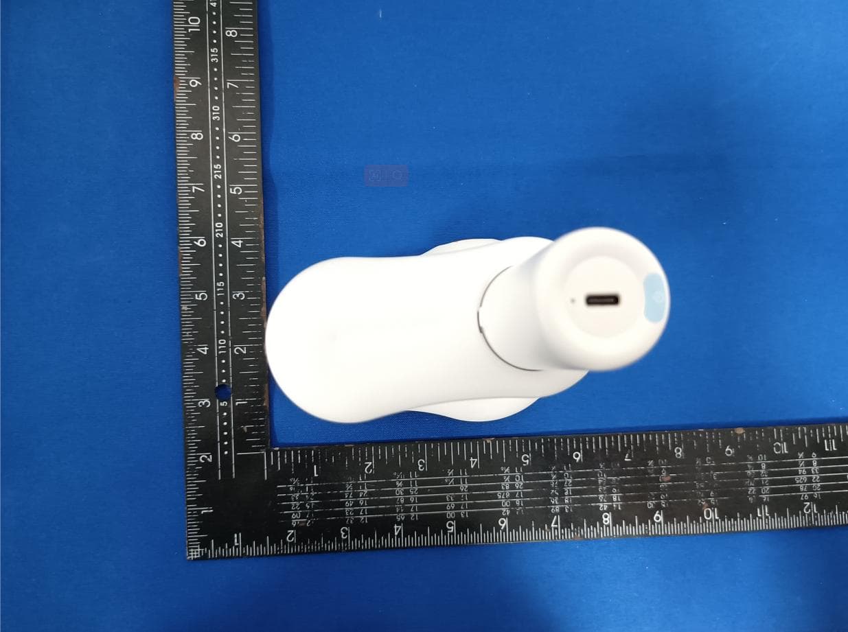
External Photos
External Photos
ID Label/Location Info
Label & label location Size:40*20mm Digital microscope FCC ID: 2 AY B Y-W04 This device complies with part 15 of the FCC Rules. Operation is subject to the following two conditions: (1) This device may not cause harmful interference, and (2) This device must accept any interference received, including interference that may cause undesired operation. Label location
Internal Photos
Internal Photos Antenna
RF Exposure Info
RF EXPOSURE EVALUATION METHOD FCC ID: 2AYBY-W04 SAR Test Exclusion Thresholds for 100 MHz – 6 GHz and ≤ 50 mm Approximate SAR Test Exclusion Power Thresholds at Selected Frequencies and Test Separation Distances are illustrated in the following Table. The 1-g and 10-g SAR test exclusion thresholds for 100 MHz to 6 GHz at test separation distances ≤ 50 mm are determined by: [(max. power of channel, including tune-up tolerance, mW)/(min. test separation distance, mm)] · [√f(GHz)] ≤ 3.0 for 1-g SAR and ≤ 7.5 for 10-g extremity SAR,where f(GHz) is the RF channel transmit frequency in GHz Power and distance are rounded to the nearest mW and mm before calculation The result is rounded to one decimal place for comparison The test exclusions are applicable only when the minimum test separation distance is ≤ 50 mm and for transmission frequencies between 100 MHz and 6 GHz. When the minimum test separation distance is < 5 mm, a distance of 5 mm is applied to determine SAR test exclusion. WIFI max possible output power (PK,conducted):5±1dbm 1dBi logarithmic terms convert to numeric result is nearly 1.259 6dbm=3.98mW 2412MHz [(max. power of channel, including tune-up tolerance, mW)/(min. test separation distance,mm)] · [√f(GHz)]=3.98/5*√2.412=1.24≤3.0 Modulation Frequency (MHz) Output Power (dBm) Max Antenna Gain (dBi) 802.11b 2412 4.06 1 802.11b 2437 4.12 1 802.11b 2462 4.90 1 802.11g 2412 2.20 1 802.11g 2437 2.89 1 802.11g 2462 3.51 1 802.11n20 2412 2.35 1 802.11n20 2437 1.73 1 802.11n20 2462 2.86 1 802.11n40 2422 0.80 1 802.11n40 2437 1.42 1 802.11n40 2452 0.31 1 Threshold at which no SAR required is 10mw and ≤ 3.0 for 1-g SAR, Separation distance is 5mm. 2437MHz [(max. power of channel, including tune-up tolerance, mW)/(min. test separation distance,mm)] · [√f(GHz)]= 8.91/5*√2.437=1.24≤3.0 Threshold at which no SAR required is 10mw and ≤ 3.0 for 1-g SAR, Separation distance is 5mm. 2462MHz [(max. power of channel, including tune-up tolerance, mW)/(min. test separation distance,mm)] · [√f(GHz)]=3.16/5*√2.48=1.25≤3.0 Threshold at which no SAR required is 10mw and ≤ 3.0 for 1-g SAR, Separation distance is 5mm. Conclusion: No SAR is required.
Test Report
No.:BCTC/RF-EMC-005 Page: 1 of 69 Edition:A.1 TEST REPORT Report No.: BCTC2007000342E Applicant: Shenzhen Microlong Technology Co., Ltd Product Name: Digital microscope Model/Type Ref.: W04 Tested Date: Jul. 21, 2020 to Sep. 24, 2020 Issued Date: Sep. 24, 2020 Shenzhen BCTC Testing Co., Ltd. Report No.: BCTC2007000342E No.:BCTC/RF-EMC-005 Page: 2 of 69 Edition:A.1 FCC ID: 2AYBY-W04 Tested by: Approved by: Tested by: The test report is effective only with both signature and specialized stamp.This result(s) shown in this report refer only to the sample(s) tested. Without written approval of Shenzhen BCTC Testing Co., Ltd, this report can’t be reproduced except in full.The tested sample(s) and the sample information are provided by the client. Product Name: Digital microscope Trademark: N/A Model/Type Ref.: W04 W01, W03 Prepared For: Shenzhen Microlong Technology Co., Ltd Address: 4th Floor, Building E, 131 Bulan Road, Nanwan Street, Longgang Dirtrict, Shenzhen City, Guangdong Province, China Manufacturer: Shenzhen Microlong Technology Co., Ltd Address: 4th Floor, Building E, 131 Bulan Road, Nanwan Street, Longgang Dirtrict, Shenzhen City, Guangdong Province, China Prepared By: Shenzhen BCTC Testing Co., Ltd. Address: 1-2F, East of B Building, Pengzhou Industrial, Fuyuan 1st Road, Qiaotou Community, Fuyong Street, Bao’an District, Shenzhen, China Sample Received Date: Jul. 21, 2020 Sample tested Date: Jul. 21, 2020 to Sep. 24, 2020 Issue Date: Sep. 24, 2020 Report No.: BCTC2007000342E Test Standards FCC Part15.247 ANSI C63.10-2013 Test Results PASS Remark: This is WIFI-2.4GHz band radio test report. Report No.: BCTC2007000342E No.:BCTC/RF-EMC-005 Page: 3 of 69 Edition:A.1 TABLE OF CONTENT Test Report Declaration Page 1. VERSION ............................................................ 5 2. TEST SUMMARY ..................................................... 6 3. MEASUREMENT UNCERTAINTY ....................................... 7 4. PRODUCT INFORMATION AND TEST SETUP ........................... 8 4.1 Product Information ..................................................... 8 4.2 Test Setup Configuration ................................................ 8 4.3 Support Equipment ..................................................... 9 4.4 Channel List ........................................................... 9 4.5 Test Mode ............................................................ 10 4.6 table of parameters of text software setting ................................ 10 5. TEST FACILITY AND TEST INSTRUMENT USED ........................ 11 5.1 Test Facility ........................................................... 11 5.2 Test Instrument Used .................................................. 11 6. CONDUCTED EMISSIONS ............................................ 13 6.1 Block Diagram Of Test Setup ........................................... 13 6.2 Limit ................................................................. 13 6.3 Test procedure ........................................................ 13 6.4 EUT operating Conditions .............................................. 13 6.5 Test Result ........................................................... 14 7. RADIATED EMISSIONS .............................................. 16 7.1 Block Diagram Of Test Setup ........................................... 16 7.2 Limit ................................................................. 17 7.3 Test procedure ........................................................ 18 7.4 EUT operating Conditions .............................................. 19 7.5 Test Result ........................................................... 20 8. RADIATED BAND EMISSION MEASUREMENT AND RESTRICTED BANDS OF OPERATION .......................................................... 27 8.1 Block Diagram Of Test Setup ........................................... 27 8.2 Limit ................................................................. 27 8.3 Test procedure ........................................................ 28 8.4 EUT operating Conditions .............................................. 28 8.5 Test Result ........................................................... 29 9. POWER SPECTRAL DENSITY TEST ................................... 31 9.1 Block Diagram Of Test Setup ........................................... 31 9.2 Limit ................................................................. 31 9.3 Test procedure ........................................................ 31 9.4 EUT operating Conditions .............................................. 31 9.5 Test Result ........................................................... 32 10. BANDWIDTH TEST .................................................. 40 10.1 Block Diagram Of Test Setup .......................................... 40 10.2 Limit ................................................................ 40 Report No.: BCTC2007000342E No.:BCTC/RF-EMC-005 Page: 4 of 69 Edition:A.1 10.3 Test procedure ....................................................... 40 10.4 EUT operating Conditions ............................................. 40 10.5 Test Result .......................................................... 41 11. PEAK OUTPUT POWER TEST ........................................ 49 11.1 Block Diagram Of Test Setup .......................................... 49 11.2 Limit ................................................................ 49 11.3 Test procedure ....................................................... 49 11.4 EUT operating Conditions ............................................. 49 11.5 Test Result .......................................................... 50 12. 100 KHZ BANDWIDTH OF FREQUENCY BAND EDGE ................... 51 12.1 Block Diagram Of Test Setup .......................................... 51 12.2 Limit ................................................................ 51 12.3 Test procedure ....................................................... 51 12.4 EUT operating Cond…
Text truncated - open the document above for the full version.
Test Setup Photos
Report No.: BCTC2007000342E 1. EUT TEST SETUP PHOTOGRAPHS Spurious emissions Te s t Report Tel: 400-788-9558 Web: https://www.bctc-lab.com BCTC/RF-EMC-0 07 Ver.:A.0 Page 1 of 2 Report No.: BCTC2007000342E Conducted emissions ※※※※※ END OF REPORT ※※※※※ Te s t Report Tel: 400-788-9558 Web: https://www.bctc-lab.com BCTC/RF-EMC-0 07 Ver.:A.0 Page 2 of 2
Contact Information
Applicant
Chen guo jun(engineer)
Test Firm
Shenzhen BCTC Testing Co., Ltd.Sally He
[email protected]15999690624
Technical Specifications
| # | Rule Parts | Frequency Range | Power Output |
|---|---|---|---|
| 1 | 15C | 2.41 GHz - 2.46 GHz | 3.09 mW |
Other Applications from Shenzhen Microlong Technology Co.,Ltd
2AYBY-CM2
Jun 25, 2023Digital microscop
Equipment Class
DTS - Digital Transmission System