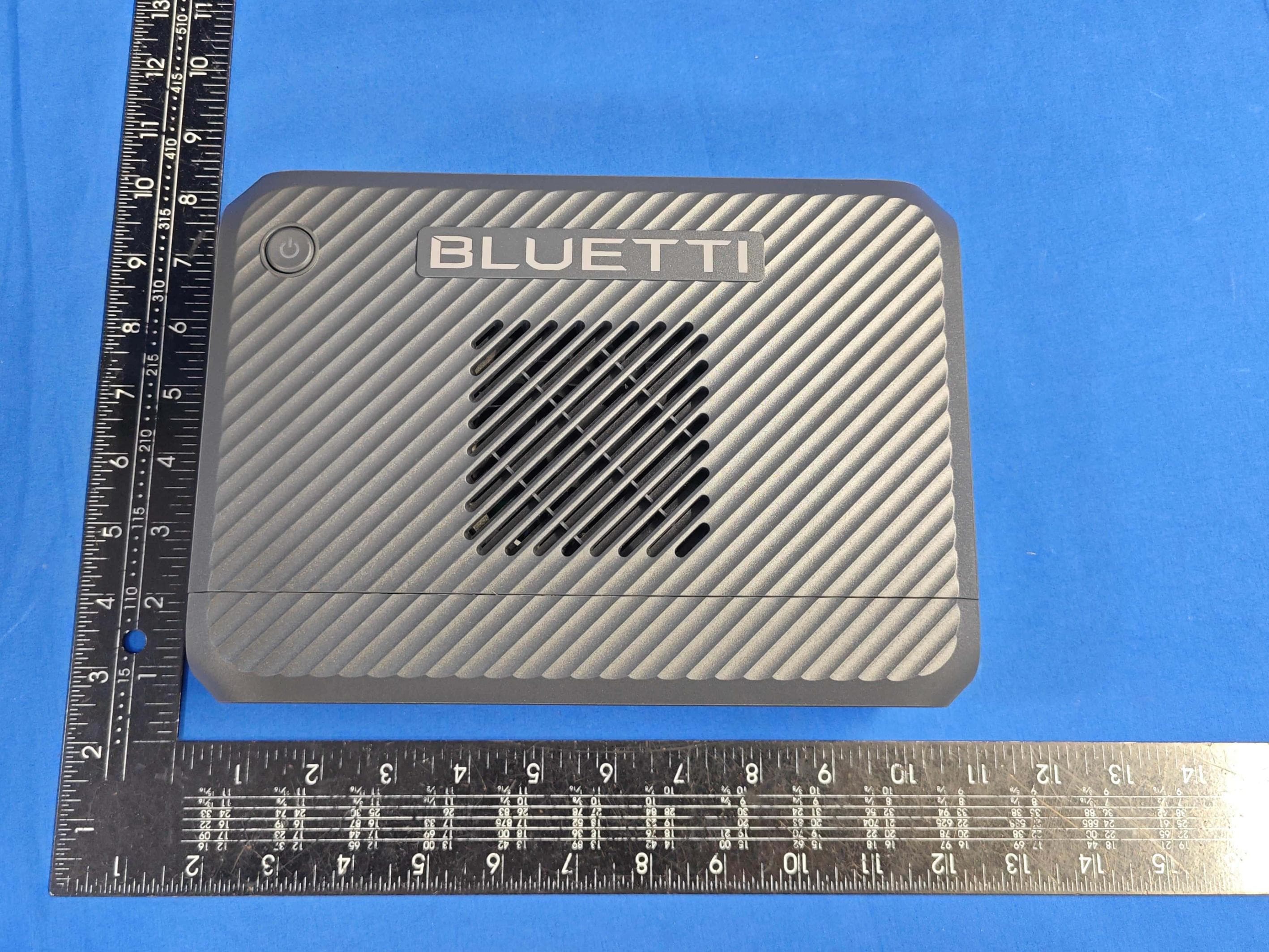
2AYT3-AC180Portable Power Station
SHENZHEN POWEROAK NEWENER CO., LTD
Click to zoom
Application Details
- Equipment Class
- DTS - Digital Transmission System
- Date of Grant
- Jun 27, 2023
- Application Purpose
- Original Equipment
- Date of Application
- Jun 27, 2023
- Equipment Note
- Portable Power Station
- Frequency Range
- 2402.00000000 - 2480.00000000
- Country
- China
Documents & Files
Document Text
Text extracted from the exhibit documents filed with the FCC. Open a document above to read the original.
Users Manual
英文说明书(美规BLUETTI) AC180 PR008-6d01A2 杨振华 23.05.10 杨振华 23.03.13 杨振华 23.03.13 更改屏幕 更改参数和配件清单 杨振华 23.05.10 A1 A2 17.0303.0531-02 技术要求 成品尺寸:A5(143X210mm) 材质:封面封底内页80g书写纸,订装 颜色:单黑印刷 28P AC180 Portable Power Station User Manual Please read this manual carefully before use and keep it for future reference. Warning 1. Charge the unit before first use. 2. Do not use solar panels with open circuit voltage higher than 60V. Solar input voltage range for the unit is DC 12V~60V. 3. Charge the unit when the SoC drops below 5%. If the SoC drops to 0, power off the unit and charge it for at least 30mins before restarting. 4. The unit is for off-grid use only. Do not connect its AC output to the grid. 5. If not used for more than 3 months, charge the unit to 40%~60% SoC and store it with the power off. For optimum battery life, discharge and charge the unit every 3 months. 6. This equipment has been tested and found to comply with the limits for a Class A digital device. Operation of this equipment in a residential area is likely to cause harmful interference in which case the user will be required to correct the interference at his own expense. 7. This product must be grounded before operation. Connect a grounding cable (recommended 14AWG1.5mm 2 /105 o C/yellow-green color) to the grounding terminal of AC180. Fasten the grounding screw (M5*10) to fix the cable. Thank You! Thank you for making BLUETTI a part of your family. From the very beginning, BLUETTI has tried to stay true to a sustainable future through green energy storage solutions for both indoor and outdoor use while delivering an exceptional eco-f riendly experience for our homes and our world. That's why BLUETTI makes its presence in 70+ countries and is trusted by millions of customers across the globe. Franch Germany Netherlands Safety Instructions General Safety Handling Storage and Usage What’s In The Box Product Overview Diagram Specifications Operating Instructions Buttons LCD Screen Charging Discharging BLUETTI App Appendix FAQs Troubleshooting Abbreviations FCC Warning Important Instructions Contents 1 1.1 1.2 1.3 2 3 3.1 3.2 4 4.1 4.2 4.3 4.4 4.5 5 5.1 5.2 5.3 5.4 5.5 05 05 07 07 08 10 10 11 12 12 14 15 17 18 19 19 20 21 21 23 1. Safety Instructions Read this manual for instructions on the proper use and safety information for the unit. Follow the warnings and instructions marked on the unit and its accessories. Pay attention to the "Instruction", "Caution", "Warning" and "Danger" symbols in this manual, and follow the instructions carefully to avoid injury or damage. The Safety Requirements provided herein are for illustrative purposes that include but are not limited to those listed in this manual. Actual operation shall comply with all applicable safety standards. If you have any questions, feel f ree to contact BLUETTI support or your local BLUETTI dealers. 1.1. General Safety • Always operate or store the unit in the conditions specified in this manual. • The installation and ambient conditions must comply with the regulations in the relevant international, national or regional standards. • Unauthorized disassembly, alteration of the equipment or modification of the software code is not allowed. BLUETTI shall not be liable for the following circumstances: • Equipment damage caused by force majeure, such as earthquake, fire, storm, flood, mudslide, etc. • Damage or loss during transportation. • Damage caused by storage conditions that do not meet the requirements specified in this manual. • Damage to the hardware or data of the equipment due to customer negligence, improper operation or intentional damage. • Damage to the system caused by a third party or the customer, including handling and installation that does not meet the requirements specified in this manual. • This product is not suitable for providing electrical service for equipment and machines that are highly dependent on the reliability of electrical power supply and that involve personal safety, such as atomic energy, aviation, medical, etc. Poweroak will not be held responsible for any personal safety accidents, fire accidents, equipment failures, etc. caused by using this product to supply power to the above equipment and machines. • Damage caused by adjustment, alteration or removal of identification marks. To avoid danger, please regulate the operation in the following manner • Do not install, use and maintain the unit in adverse weather conditions such as lightning, rain, snow and strong breezes (including but not limited to handling and operating the unit, plugging and unplugging signal connections to outdoor facilities, working at height, outdoor installations, etc.). JUST POWER ON05 • The transportation, wiring and maintenance shall comply with all applicable laws, regulations and standards. • User-provided materials and tools required shall meet the requirements specified in applicable laws, regulations and relevant standards. • Always turn off the power source before starting any electrical work. • Do not clean the unit with water. • Do not disassemble, modify, tamper with or repair the unit on your own. • Regularly inspect the unit and its accessories for damage or deterioration. • Use a tester to check for the presence of dangerous voltage before touching any conductor or terminal. • If the unit’s shell is cracked during transportation or use, do not use it and contact BLUETTI support or your local BLUETTI dealers. • Use a dry powder extinguisher if the unit catches fire. • In case of fire, EVACUATE the building or affected area immediately, activate the closest FIRE ALARM system and CALL 9-1-1 or your local emergency phone number. • Use genuine cables and accessories provided by BLUETTI. • Keep the unit away f rom heat sources or high temperatures, and do not expose it to direct sunlight. • Do not store the unit with flammable liquids, gases, or explosive materials. • Make sure the area where you are using the unit is well ventilated and spacious. • Do no…
Text truncated - open the document above for the full version.
Cover Letter(s)
Agent Authorization Company: SHENZHEN POWEROAK NEWENER CO., LTD Address: F19, BLD No.1, Kaidaer Tongsha Rd No.168, Xili Street, Nanshan, Shenzhen, China Product Name: Portable Power Station Model Number(s): AC180 Product Description: Portable Power Station We authorize MiCOM Labs Inc., 575 Boulder Court, Pleasanton, California 94566, USA, to act on our behalf on all matters concerning the certification of above named equipment. We declare that MiCOM Labs Inc. is allowed to forward all information related to the approval and certification of equipment to the regulatory agencies as required and to discuss any issues concerning the approval application. Any and all acts carried out by MiCOM Labs on our behalf shall have the same effect as acts of our own. Signature: Date: May 30, 2023 Name: Cara Zou Title: Manager Company: SHENZHEN POWEROAK NEWENER CO., LTD
ID Label/Location Info
深圳市德兰明海科技有限公司 Shenzhen PowerOak Newener Co.,ltd 23.04.23 A1 A2 PR008-6e01A3 17.0301.1185-03 AC180 +0/-0.3mm 22.11.30 A4 A5 A6 A7 Portable Power Station Model No.: AC180 Battery Capacity: 1152Wh, 32V 36Ah +0/-0.3mm 138mm 6 R5mm 70mm MADE IN CHINAP/N:17.0301.1185-03A3 C:0 M:0 Y:0 K:25 Output: AC: 120V 50/60Hz, 1800W/1800VA Max USB-A: 5V 3A, 15W Total x2 USB-C: 5/9/12/15/20V 3A; 20V 5A (E-Marker chip built-in) Wireless Charging: 5/7.5/10/15W Cigarette Lighter Socket: 12V 10A AC and DC output: 1800W Total Discharging Temperature: -20 o C-40 o C Charging Temperature: 0 o C-40 o C Working Humidity: 10%-90% Input: AC: 120V 50/60Hz, 15A Max DC/PV: 12V-60V 10A, 500W Max 23.1.6 23.2.17 23.4.23 FCC ID:2AYT3-AC180 IC:29079-AC180 This device complies with Part 15 of the FCC Rules.Operation is subject to the following two conditions:(1) this device may not cause harmful interference, and (2) this device must accept any interference received,including interference that may cause undesired operation. SHENZHEN POWEROAK NEWENER CO., LTD. Add: F19, BLD No.1, Kaidaer, Tongsha Rd No.168, Xili Street, Nanshan, Shenzhen, China Label location map
Internal Photos
Report No.: AGC01741230301AP03 Page 1 of 11 INTERNAL PHOTOS OPEN VIEW OF EUT (FIGURE 1) OPEN VIEW OF EUT (FIGURE 2) Report No.: AGC01741230301AP03 Page 2 of 11 OPEN VIEW OF EUT (FIGURE 3) ANTENNA CLOSE-UP PHOTO-1 WPT Antenna Report No.: AGC01741230301AP03 Page 3 of 11 ANTENNA CLOSE-UP PHOTO-2 ANTENNA CLOSE-UP PHOTO-3 Report No.: AGC01741230301AP03 Page 4 of 11 ANTENNA CLOSE-UP PHOTO-4 INTERNAL VIEW OF EUT (FIGURE 1) BT Antenna Report No.: AGC01741230301AP03 Page 5 of 11 INTERNAL VIEW OF EUT (FIGURE 2) INTERNAL VIEW OF EUT (FIGURE 3) Report No.: AGC01741230301AP03 Page 6 of 11 INTERNAL VIEW OF EUT (FIGURE 4) INTERNAL VIEW OF EUT (FIGURE 5) Report No.: AGC01741230301AP03 Page 7 of 11 INTERNAL VIEW OF EUT (FIGURE 6) INTERNAL VIEW OF EUT (FIGURE 7) Report No.: AGC01741230301AP03 Page 8 of 11 INTERNAL VIEW OF EUT (FIGURE 8) INTERNAL VIEW OF EUT (FIGURE 9 Report No.: AGC01741230301AP03 Page 9 of 11 INTERNAL VIEW OF EUT (FIGURE 10) INTERNAL VIEW OF EUT (FIGURE 11) Report No.: AGC01741230301AP03 Page 10 of 11 INTERNAL VIEW OF EUT (FIGURE 12) INTERNAL VIEW OF EUT (FIGURE 13) Report No.: AGC01741230301AP03 Page 11 of 11 BATTERY VIEW OF EUT ****************************************End of Report*************************************
RF Exposure Info
RF EXPOSURE EVALUATION 1. PRODUCT INFORMATION FCC ID 2AYT3-AC180 Product Description Portable Power Station Model Name BLUETTI Frequency Band (Operating) WLAN: 2.412GHz ~ 2.462GHz WLAN: 5.18GHz ~ 5.32GHz / 5.50GHz ~ 5.70GHz WLAN: 5.745GHz ~ 5825GHz Bluetooth: 2.402GHz ~ 2.480GHz Others (WPT: 110.5KHz-205KHz) Device Category Portable (<20cm separation) Mobile (≥20cm separation) Others: Antenna Diversity BT: PCB Antenna WPT: Coil Antenna Max. Output Power BLE 1M: 0.996dBm (Max) BLE 2M: 0.870dBm (Max) Field Strength of Fundamental WPT: 63.36dBuV/m (Max) Antenna Gain -2.31dBi Minimum Assessment Distance 20mm Evaluation Applied MPE Evaluation SAR Evaluation Evaluation Result Pass 2. PORTABLE DEVICE EVALUATION METHOD AND LIMIT Following FCC KDB 447498 D01 “General SAR test exclusion guidance” The corresponding SAR Exclusion Threshold condition, listed below: 1) The 1-g and 10-g SAR test exclusion thresholds for 100 MHz to 6 GHz at test separation distances ≤50 mm are determined by: [(max. power of channel, including tune-up tolerance, mW)/(min. test separation distance, mm)] [√f(GHz)] ≤ 3.0 for 1-g SAR, and ≤ 7.5 for 10-g extremity SAR, where f(GHz) is the RF channel transmit frequency in GHz. Power and distance are rounded to the nearest mW and mm before calculation. The result is rounded to one decimal place for comparison The test exclusions are applicable only when the minimum test separation distance is ≤50 mm and for transmission frequencies between 100 MHz and 6 GHz. When the minimum test separation distance is < 5 mm, a distance of 5 mm is applied to determine SAR test exclusion. 2) At 100 MHz to 6 GHz and for test separation distances > 50 mm, the SAR test exclusion threshold is determined according to the following: a) [Threshold at 50 mm in step 1) + (test separation distance - 50mm) ( f(MHz)/150)] mW, at 100MHz to 1500 MHz; b) [Threshold at 50 mm in step 1) + (test separation distance - 50 mm)-10] mW at > 1500 MHz and ≤6 GHz; 3) At frequencies below 100 MHz, the following may be considered for SAR test exclusion. a) The threshold at the corresponding test separation distance at 100 MHz in step 2) is multiplied by [1 + log(100/f(MHz))] for test separation distances > 50 mm and < 200 mm. b) The threshold determined by the equation in a) for 50 mm and 100 MHz is multiplied by 1/2 for test separation distances ≤ 50 mm. c) SAR measurement procedures are not established below 100 MHz. When SAR test exclusion cannot be applied, a KDB inquiry is required to determine SAR evaluation requirements for any test results to be acceptable. 3. MOBILE DEVICE EVALUATION METHOD AND LIMIT Human exposure to RF emissions from mobile devices (47 CFR §2.1091) may be evaluated based on the MPE limits adopted by the FCC for electric and magnetic field strength and/or power density, as appropriate, since exposures are assumed to occur at distances of 20 cm or more from persons. LIMITS FOR GENERAL POPULATION / UNCONTROLLED EXPOSURE Frequency Range (MHz) E-field Strength (E) (V/m) Magnetic Field Strength (H) (A/m) Power Density (S) (mW/cm 2 ) Averaging Time |E| 2 , |H| 2 or S (Minutes) 0.3 -- 1.34 614 1.63 (100)* 30 1.34 -- 30 824/f 2.19/f (180/f 2 )* 30 30 -- 300 27.5 0.073 0.2 30 300 -- 1500 -- -- f/1500 30 1500 -- 100,000 -- -- 1.0 30 *Note: 1. f= Frequency in MHz * Plane-wave Equivalent Power Density 2. The averaging time for General Population/Uncontrolled exposure to fixed transmitters is not applicable for mobile and portable transmitters. See 47 CFR §§2.1091 and 2.1093 on source-based time-averaging requirement for mobile and portable transmitters. S=PG/4πR² Where: S=power density P=power input to antenna G=power gain of the antenna in the direction of interest relative to an isotropic radiator R=distance to the center of radiation of the antenna 4. CONCLUSION Since Source-base time average power is below SAR test exclusion power thresholds, the SAR evaluation is not required. 5. MEASUREMENT RESULT A minimum test separation distance ≥ 20 cm is required between the antenna and radiating structures of the device and nearby persons to apply mobile device exposure limits. The distance must be at least 20 cm and fully supported by the operating and installation configurations of the transmitter and its antenna(s), according to the source-based time-averaged maximum power requirements of § 2.1091(d)(2). In cases where cable losses or other attenuations are applied to determine compliance, the most conservative operating configurations and exposure conditions must be evaluated. BT WLAN: Antenna Gain=-2.31dBi (Numeric 0.59), π=3.14 Note: 1. Only the worst case recorded. 2. Max Power (dBm) = Field Strength of Fundamental (dBuV/m@3m)-95.23 3. Max Power (mW) = 10^ (Max power (dBm)/10) 4. The wireless technology multi transmission calculation result is: 0.0002/1+0.00000023=0.00020023<1 Test Mode Test Frequency (MHz) Max.Output Power (dBm) Max.Output Power (mW) Power Density (mW/cm 2 ) Measurement Limit (mW/cm 2 ) BLE 1M 2480 0.996 1.258 0.00015 1 BLE 2M 2480 0.870 1.222 0.00014 1 WPT 0.130 -31.87 0.00065013 0.00129405 --
Test Report
Page 1 of 62 FCC Test Report Report No.: AGC01741230301FE02 FCC ID : 2AYT3-AC180 APPLICATION PURPOSE : Original Equipment PRODUCT DESIGNATION : Portable Power Station BRAND NAME : BLUETTI MODEL NAME : AC180 APPLICANT : SHENZHEN POWEROAK NEWENER CO., LTD DATE OF ISSUE : Apr. 21, 2023 STANDARD(S) : FCC Part 15.247 REPORT VERSION : V1.0 Attestation of Global Compliance (Shenzhen) Co., Ltd Report No.: AGC01741230301FE02 Page 2 of 62 REPORT REVISE RECORD Report Version Revise Time Issued Date Valid Version Notes V1.0 / Apr. 21, 2023 Valid Initial Release Report No.: AGC01741230301FE02 Page 3 of 62 TABLE OF CONTENTS 1. VERIFICATION OF COMPLIANCE .................................................................................................................. 5 2. GENERAL INFORMATION .............................................................................................................................. 6 2.1. PRODUCT DESCRIPTION ........................................................................................................................ 6 2.2. TABLE OF CARRIER FREQUENCYS ....................................................................................................... 6 2.3. RELATED SUBMITTAL(S)/GRANT(S) ....................................................................................................... 7 2.4. TEST METHODOLOGY ............................................................................................................................. 7 2.5. SPECIAL ACCESSORIES .......................................................................................................................... 7 2.6. EQUIPMENT MODIFICATIONS ................................................................................................................. 7 2.7. ANTENNA REQUIREMENT ....................................................................................................................... 7 3. MEASUREMENT UNCERTAINTY ................................................................................................................... 8 4. DESCRIPTION OF TEST MODES ................................................................................................................... 9 5. SYSTEM TEST CONFIGURATION ................................................................................................................ 10 5.1. CONFIGURATION OF TESTED SYSTEM ............................................................................................... 10 5.2. EQUIPMENT USED IN TESTED SYSTEM .............................................................................................. 10 5.3. SUMMARY OF TEST RESULTS .............................................................................................................. 10 6. TEST FACILITY .............................................................................................................................................. 11 7. PEAK OUTPUT POWER ................................................................................................................................ 12 7.1. MEASUREMENT PROCEDURE .............................................................................................................. 12 7.2. TEST SET-UP (BLOCK DIAGRAM OF CONFIGURATION) .................................................................... 12 7.3. LIMITS AND MEASUREMENT RESULT .................................................................................................. 13 8. BANDWIDTH .................................................................................................................................................. 17 8.1. MEASUREMENT PROCEDURE .............................................................................................................. 17 8.2. TEST SET-UP (BLOCK DIAGRAM OF CONFIGURATION) .................................................................... 17 8.3. LIMITS AND MEASUREMENT RESULTS ............................................................................................... 17 9. CONDUCTED SPURIOUS EMISSION........................................................................................................... 25 9.1. MEASUREMENT PROCEDURE .............................................................................................................. 25 9.2. TEST SET-UP (BLOCK DIAGRAM OF CONFIGURATION) .................................................................... 25 9.3. MEASUREMENT EQUIPMENT USED .................................................................................................... 25 9.4. LIMITS AND MEASUREMENT RESULT .................................................................................................. 25 10. MAXIMUM CONDUCTED OUTPUT POWER SPECTRAL DENSITY ........................................................ 38 10.1. MEASUREMENT PROCEDURE ............................................................................................................ 38 10.2. TEST SET-UP (BLOCK DIAGRAM OF CONFIGURATION) .................................................................. 38 10.3. MEASUREMENT EQUIPMENT USED .................................................................................................. 38 10.4. LIMITS AND MEASUREMENT RESULT................................................................................................ 38 11. RADIATED EMISSION ................................................................................................................................. 42 11.1. MEASUREMENT PROCEDURE ............................................................................................................ 42 11.2. TEST SETUP .......................................................................................................................................... 43 11.3. LIMITS AND MEASUREMENT RESULT................................................................................................ 44 11.4. TEST RESULT .........…
Text truncated - open the document above for the full version.
Test Report
Page 1 of 18 Test Report Verified code: Report No.: E20230306359801-1-G1 Customer: Guangdong Bestcore Internet of Things Technology CO., Ltd. Address: Room1501,15F,ShuMao Building,6 Xiangxing Road, Torch Development District,Zhong shan Sample Name: LE ANT A Sample Model: LE ANT A Receive Sample Date: Mar.07,2023 Test Date: Mar.07,2023 ~ Mar.07,2023 Reference Document: ANSI IEEE 149-2021 Part 7, Part 8, Part 10 Test Result: Not make judgment Prepared by: Reviewed by: Approved by: GRG METROLOGY & TEST GROUP CO., LTD. Issued Date: GRG METROLOGY & TEST GROUP CO., LTD. Address: No.163,Pingyun Road, West of Huangpu Avenue, Guangzhou, Guangdong, China Tel:(+86)400-602-0999 FAX:(+86)020-38698685 Web:http://www.grgtest.com 348480 2023-03-17 Report No.: E20230306359801-1-G1 Page 2 of 18 Statement 1. The report is invalid without "special seal for inspection and testing"; some copies are invalid; The report is invalid if it is altered or missing; The report is invalid without the signature of the person who prepared, reviewed and approved it. 2. The sample information is provided by the client and responsible for its authenticity; The content of the report is only valid for the samples sent this time. 3. When there are reports in both Chinese and English, the Chinese version will prevail when the language problems are inconsistent. 4. If there is any objection concerning the report, please inform us within 15 days from the date of receiving the report. 5. Without the agreement of the laboratory, the client is not authorized to use the test results for unapproved propaganda. ------------ The following blanks ------------ Report No.: E20230306359801-1-G1 Page 3 of 18 TABLE OF CONTENTS 1. TEST RESULT SUMMARY ...................................................................................................................... 5 2. GENERAL DESCRIPTION OF EUT ......................................................................................................... 6 2.1 APPLICANT INFORMATION ...................................................................................................................... 6 2.2 MANUFACTURER ........................................................................................................................................ 6 2.3 FACTORY ...................................................................................................................................................... 6 2.4 BASIC DESCRIPTION OF EUT ................................................................................................................... 6 2.5 TEST SCENE .................................................................................................................................................. 6 2.6 SAMPLE WORK DESCRIPTION ................................................................................................................. 6 2.7 ASSISTIVE DEVICE INFORMATION......................................................................................................... 7 2.8 SAMPLE CONNECTION DIAGRAM .......................................................................................................... 7 3. LABORATORY .......................................................................................................................................... 8 4. MEASUREMENT UNCERTAINTY .......................................................................................................... 9 5. EQUIPMENT AND TOOLS USED DURING TEST .............................................................................. 10 6. ANTENNA RADIATION PERFORMANCE MEASUREMENT ........................................................... 11 6.1 LIMITS ......................................................................................................................................................... 11 6.2 TEST PROCEDURE ..................................................................................................................................... 11 6.3 CONFIGURATION OF SYSTEM UNDER TEST ...................................................................................... 12 6.4 TEST PHOTOS ............................................................................................................................................. 12 6.5 TEST RESULTS ........................................................................................................................................... 13 7. PHOTOGRAPH OF THE EUT ................................................................................................................. 17 ------------ The following blanks ------------ Report No.: E20230306359801-1-G1 Page 4 of 18 REPORT ISSUED HISTORY Report Version Report No. Description Compile Date 1.0 E20230306359801-1 Original Issue 2023-03-07 2.0 E20230306359801-1-G1 Update 2023-03-17 Note 1: This report E20230306359801-1-G1 is the modification of report E20230306359801-1. On the basis of the original report, Update Product Name Bluetooth Module to LE ANT A, Product Model BC204 to LE ANT A on page 1,6,13 of the report, and add Product Size: Antenna Size: 8.5mm*5.51mm*0.03mm, add Antenna Type: PCB Antenna, add Software Version: /, Hardware Version: /, add Manufacturer: Guangdong Bestcore Internet of Things Technology CO., Ltd. on page 6 of the report, and the original report E20230306359801-1 is invalid. ------------ The following blanks ------------ Report No.: E20230306359801-1-G1 Page 5 of 18 1. TEST RESULT SUMMARY Test Item Test Frequency Test Method Test Scene Test Result Gain 2400 MHz ~2500MHz ANSI IEEE 149-2021 Part 8 scene 1 / 1) Radiation efficiency 2400 MHz ~2500MHz ANSI IEEE 149-2021 Part 10 scene 1 / 1) Radiation pattern 2400 MHz ~2500MHz ANSI IEEE 149-2021 Part 7 scene 1 / 1) Note 1):Customer-defined test, test results do not make judgment. ------------ The following blanks ------------ . Report No.: E20230306359801-1-G1 Page 6 of 18 2. GENERAL DESCRIPTION OF EUT 2.1 APPLI…
Text truncated - open the document above for the full version.
Test Setup Photos
Report No.: AGC01741230301AP02 Page 1 of 6 TEST SETUP PHOTOS BT RADIATED EMISSION TEST SETUP BELOW 1GHz RADIATED EMISSION TEST SETUP ABOVE 1GHz Report No.: AGC01741230301AP02 Page 2 of 6 AC POWER LINE CONDUCTED TEST SETUP RF CONDUCTED TEST SETUP Report No.: AGC01741230301AP02 Page 3 of 6 WPT RADIATED EMISSION TEST SETUP BELOW 30MHz RADIATED EMISSION TEST SETUP BELOW 1GHz Report No.: AGC01741230301AP02 Page 4 of 6 AC POWER LINE CONDUCTED TEST SETUP RF HEALTH ASSESSMENT TEST PHOTOS H-Field & E-Field Strength_ Position A Report No.: AGC01741230301AP02 Page 5 of 6 H-Field & E-Field Strength_ Position B H-Field & E-Field Strength_ Position C Report No.: AGC01741230301AP02 Page 6 of 6 H-Field & E-Field Strength_ Position D H-Field & E-Field Strength_ Position E ****************************************End of Report*************************************
Contact Information
Applicant
Cara Zou(Manager)
Technical Contact
Test Firm
Attestation of Global Compliance (Shenzhen) Co., LDoris Li
[email protected]+86-755-25234088
Technical Specifications
| # | Rule Parts | Frequency Range | Power Output |
|---|---|---|---|
| 1 | 15C | 2.40 GHz - 2.48 GHz | 1.30 mW |
Other Applications from SHENZHEN POWEROAK NEWENER CO., LTD
2AYT3-CHARGER2
Dec 02, 2025DC-DC Charger
Equipment Class
DTS - Digital Transmission System2AYT3-FRIDGEPOWER
Nov 27, 2025Portable Power Station
Equipment Class
DTS - Digital Transmission System2AYT3-F045D
Nov 28, 2024Refrigerator
Equipment Class
DTS - Digital Transmission System2AYT3-CHARGER1
Jul 16, 2024DC-DC Charger
Equipment Class
DTS - Digital Transmission System2AYT3-EB3A01
Apr 07, 2024Portable Power Station
Equipment Class
DTS - Digital Transmission System