2AYT3-EB3APortable Power Station
SHENZHEN POWEROAK NEWENER CO., LTD
Click to zoom
Application Details
- Equipment Class
- DTS - Digital Transmission System
- Date of Grant
- May 31, 2022
- Application Purpose
- Original Equipment
- Date of Application
- May 31, 2022
- Equipment Note
- Portable Power Station
- Frequency Range
- 2402.00000000 - 2480.00000000
- Country
- China
Documents & Files
Document Text
Text extracted from the exhibit documents filed with the FCC. Open a document above to read the original.
Users Manual
BLUETTI EB3A User Manual Portable Power Station Canada USA Mexico Australia Germany Italy Spain South Af rica Nigeria UK Sweden Austria Switzerland Japan China Malaysia Singapore Philippines New Zealand Thank You Thank you for making BLUETTI a part of your family. From the very beginning, BLUETTI has tried to stay true to a sustainable future through green energy storage solutions for both indoor and outdoor use while delivering an exceptional eco-f riendly experience for our homes and our world. That's why BLUETTI makes its presence in 70+ countries and is trusted by millions of customers across the globe. CONTENTS Before You Begin Safety Instructions What's In The Box Standard Packaging Product Overview Diagram Specifications Operation LCD Screen Powering On/Off Standand Mode UPS Setting APP Charging Discharging Appendix FAQs (Frequently Asked Questions) Technical Support 4 5 6 6 7 7 8 9 9 10 10 11 11 12 12 14 15 15 16 3 Before You Begin The information contained herein is subject to change without notice. For the latest version, please visit https://www.bluettipower.com/pages/user-guides. The user manual contains instructions and notes on the operation and use of this unit. BLUETTI recommends that you use genuine accessories f rom BLUETTI. BLUETTI shall not be responsible for any damage or expense that might result f rom the use of parts other than genuine parts f rom the BLUETTI. For your safety and benefit, please read carefully before using and keep it handy for future reference. 4 Failure to follow these guidelines may cause damage to your unit and injury to yourself or others. Keep this unit away f rom fire, humidity and dust. Make sure the place where you are using the unit is well ventilated and spacious. DO NOT place the unit on an unstable or tilted surface. Turn off the unit IMMEDIATELY in case of malfunction. When not using the unit for extended periods of time, power off the unit and disconnect the AC charging cable f rom the outlet. Recommended storage temperature: 14-113 O F/-10-45 O C. Charge the unit to 80% SOC every 3-6 months for long-term storage. 5 Safety Instructions What's In The Box 6 AC Charging Cable Solar Charging CableCar Charging Cable User Manual Warranty CardEB3A Portable Power Station Standard Packaging Note: Package details are subject to change without prior notice. * AC Charging Cable: 71in/180cm. Car Charging Cable: 28in/72cm, 16AWG, Cigarette Lighter Port to DC7909. Solar Charging Cable: 59in/150cm, 16AWG, MC4 to DC7909. USB-C to USB-C Cable: 59in/150cm, 16AWG. USB-C to USB-C Cable * Below accessories are not included in standard packaging and can be purchased at https://www.bluettipower.com/. Product Overview 7 Diagram 1. Cigarette Lighter Port 2. DC5521 Port 3. DC Power Button 4. DC Input Port 5. AC Input Port 6. AC Circuit Breaker* 7. Wireless Charging Pad 8. LCD Screen 9. LED Lamp 10. LED Lamp Button 11. USB-C Port 12. USB-A Port 13. AC Output Port 14. AC Power Button 1 2 3 4 5 6 7 9 10 11 13 12 14 8 * A circuit breaker is an electrical safety switch designed to protect your unit f rom damage caused by overcurrent or short circuit. When the AC current exceeds 10A, it will trip automatically. Press it once to reset the unit after these symptoms cleared. 8 Note: EB3A supports a 268W Max. AC input by default. When operating at a temperature of 10-40 o C, you can set the Turbo Charging on BLUETTI App and get a 430W Max. input. EB3A also supports 430W Max. PV + AC dual charging. Solar power serves as the primary power supply to the EB3A when the total input exceeds 430W. Specifications Product Item EB3A USEB3A EU/UK/AU General AC Output DC Output AC Input Battery Capacity Cell Type Dimensions (L*W*H) Weight Discharging Temperature Charging Temperature Working Humidity 268.8Wh(12Ah) LiFePO4 10.04*7.09*7.20IN/255*180*183MM 10.14LB/4.6KG -4-104°F/-20-40°C 32-104°F/0-40°C 10-90% Power Surge Voltage Current Voltage Current Voltage Current Voltage Current Power Power 12VDC 10A 12VDC 10A 5VDC 3A 100W Max. 5/7.5/10/15W 600W 1200W Power Voltage Current Frequency 268/430W Max. DC Input Power Voltage Current 200W Max. 12-28VDC 8.5A Max. 120VAC 5A 220-240VAC 2.6A 120VAC 9A 60Hz 220-240VAC 4A 50Hz Cigarette Lighter Port *1 DC5521 *2 USB-A *2 USB-C PD3.0 *1 Wireless Charging *1 Operation 9 LCD Screen a: ECO Mode b: Turbo Charging c: Low-battery Alert d: Input Power e: Output Power f: Battery Capacity g: AC Frequency h: Temperature Anomaly Alert i: Short-circuit Alert j: Overload Alert k: Remaining Time Indicator* l: UPS Indicator m: AC Indicator n: DC Indicator * This indicator tells the remaining charge/discharge time. a d f h c e g b i j l mn k 10 Setting Mode: When the AC power is off and LCD screen is on, press and hold AC and DC power buttons simultaneously for 2s. The AC f requency indicator will flash. Press and hold AC and DC power buttons simultaneously to exist ‘Setting Mode’ . Note: If the unit has been idle for 1 minute under ‘Setting Mode’ , it will automatically exit ‘Setting Mode’ and the setting changes will not be saved. ECO Mode: Under 'Setting Mode', press the DC power button to turn it on/off. Note: When on this mode, the AC/DC output will automatically turn off after 4-hour low (≤10W for AC, ≤1W for DC) or no load to save power. Note: Please turn on the DC power to enable the wireless charging. Press any button, the LCD screen will stay on for 30 seconds. Powering off: Press and hold power buttons to shut down corresponding output. Note: Press and hold any button for at least 3s, the unit will be off. Powering on: Press and hold the AC/DC Power Button for 1s to start up corresponding output. Green light(on the button) LCD Display OFF OFF Powering On/Off Green light(on the button) LCD Display ON ON Standand Mode 11 UPS Bypass Mode: Connect the EB3A with the AC power and the ‘UPS’ will be on display. Then turn on the AC output. When on this mode, the AC power will directly support the loads on AC output ports and charge the EB3A. Note: Max. outp…
Text truncated - open the document above for the full version.
Cover Letter(s)
SHENZHENPOWEROAKNEWENERCO.,LTD 19thfloor,Tower1,KaidaerBuilding,TongshaRoadNo.168,XiLiTown,NanshanDistrict,Shenzhen,China OfficeofEngineeringTechnology FederalCommunicationsCommission 7435OaklandMillsRoad Columbia,MD21046 USA Date:Apr.28,2022 Subject;RequestforConfidentiality FCCID:2AYT3-EB3A ToWhomItMayConcern, PursuanttotheprovisionsoftheCommission’srulesTitle47Sections§0.457and§0.459,we arerequestingtheCommissiontowithholdthefollowingattachment(s)asconfidential documentsfrompublicdisclosureindefinitely. Thesedocumentscontaindetailedsystemandequipmentdescriptionsandareconsideredas proprietaryinformationinoperationoftheequipment.Thepublicdisclosureofthesedocuments mightbeharmfultoourcompanyandwouldgivecompetitorsanunfairadvantageinthemarket. SchematicDiagram BlockDiagram OperationalDescription PartsList Tune-upProcedure Inadditionaltoabovementioneddocuments,inordertocomplywiththemarketingregulations inTitle47CFR§2.803andtheimportationrulesinTitle47CFR§2.1204,whileensuringthat businesssensitiveinformationremainsconfidentialuntiltheactualmarketingofnewly authorizeddevices,werequestShortTermConfidentialityofthefollowingattachment(s); ExternalPhotos TestSetupPhotos InternalPhotos UserManual For45days,pursuanttoPublicNoticeDA04-1705. OR For180dayspursuanttoKDB726920D01. Itisourunderstandingthatallmeasurementtestreports,FCCIDlabelformatand correspondenceduringthecertificationreviewprocesscannotbegrantedasconfidential documentsandthisinformationwillbeavailableforpublicreviewoncethegrantofequipment authorizationisissued. Sincerely, Signature: Name:CaraZou Title:Manager
Cover Letter(s)
Agent Authorization Company: SHENZHEN POWEROAK NEWENER CO., LTD Address: 19th floor, Tower 1, Kaidaer Building, Tongsha Road No.168, XiLi Town, Nanshan District, Shenzhen, China Product Name: Portable Power Station Model Number(s): EB3A Product Description: Portable Power Station We authorize MiCOM Labs Inc., 575 Boulder Court, Pleasanton, California 94566, USA, to act on our behalf on all matters concerning the certification of above named equipment. We declare that MiCOM Labs Inc. is allowed to forward all information related to the approval and certification of equipment to the regulatory agencies as required and to discuss any issues concerning the approval application. Any and all acts carried out by MiCOM Labs on our behalf shall have the same effect as acts of our own. Signature: Date: Apr. 28, 2022 Name: Cara Zou Title: Manager Company: SHENZHEN POWEROAK NEWENER CO., LTD
External Photos
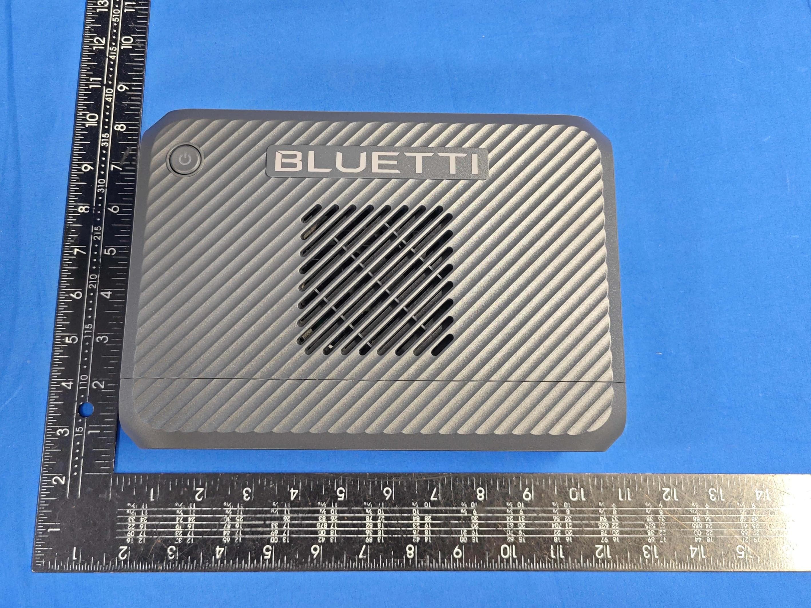
Report No.: AGC01741220401AP02 Page 1 of 3 EXTERNAL PHOTOS TOP VIEW OF EUT BOTTOM VIEW OF EUT Report No.: AGC01741220401AP02 Page 2 of 3 FRONT VIEW OF EUT BACK VIEW OF EUT Report No.: AGC01741220401AP02 Page 3 of 3 LEFT VIEW OF EUT RIGHT VIEW OF EUT ****************************************End of Report****************************************
ID Label/Location Info
FCC ID Label Location + 0/-0.3mm +0/-0.3mm Output: AC × 2: 120V~50/60Hz, 600W Total USB-A × 2: 5V 3A Total USB-C × 1: 5/9/12/15/20V 3A; 20V 5A (E-Marker chip built-in) DC 5521 × 2: 12V 10A Total Cigarette Lighter × 1: 12V 10A (DC 5521 and Cigarette Lighter 10A Total) Wireless Charge × 1: 5W/7.5W/10W/15W AC and DC output : 600W Total Portable Power Station Model No.: EB3A Battery Capacity: 268.8Wh, 22.4V 12Ah Input: AC: 120V~50/60Hz, 9A MAX DC: 12-28V 8.5A, 200W MAX Discharge Temperature: -20-40 o C Charging Temperature: 0-40 o C Working Humidity: 10%-90% SHENZHEN POWEROAK NEWENER CO.,LTD 99.5mm 5 R3mm 49.5mm MADE IN CHINAP/N:17.0301.1033-02A2 FCC ID: 2AYT3-EB3A This device complies with Part 15 of the FCC Rules. Operation is subject to the following two conditions: (1) this device may not cause harmful interference, and (2) this device must accept any interference received, including interference that may cause undesired operation. Bottom of the Product
Internal Photos
Report No.: AGC01741220401AP02 Page 1 of 8 INTERNAL PHOTOS PORT VIEW OF EUT (FIGURE 1) PORT VIEW OF EUT (FIGURE 2) Report No.: AGC01741220401AP02 Page 2 of 8 OPEN VIEW OF EUT (FIGURE 1) ANTENNA CLOSE-UP PHOTO-1 BT Antenna Report No.: AGC01741220401AP02 Page 3 of 8 ANTENNA CLOSE-UP PHOTO-2 INTERNAL VIEW OF EUT (FIGURE 1) WPT Antenna Report No.: AGC01741220401AP02 Page 4 of 8 INTERNAL VIEW OF EUT (FIGURE 2) INTERNAL VIEW OF EUT (FIGURE 3) Report No.: AGC01741220401AP02 Page 5 of 8 INTERNAL VIEW OF EUT (FIGURE 4) INTERNAL VIEW OF EUT (FIGURE 5) Report No.: AGC01741220401AP02 Page 6 of 8 INTERNAL VIEW OF EUT (FIGURE 6) INTERNAL VIEW OF EUT (FIGURE 7) Report No.: AGC01741220401AP02 Page 7 of 8 INTERNAL VIEW OF EUT (FIGURE 8) INTERNAL VIEW OF EUT (FIGURE 9) Report No.: AGC01741220401AP02 Page 8 of 8 INTERNAL VIEW OF EUT (FIGURE 10) INTERNAL VIEW OF EUT (FIGURE 11) ****************************************End of Report****************************************
RF Exposure Info
RF EXPOSURE EVALUATION 1. PRODUCT INFORMATION Product Description Portable Power Station Test Model EB3A FCC ID 2AYT3-EB3A 2. EVALUATION METHOD According to 447498 D01 General RF Exposure Guidance v06 The 1-g and 10-g SAR test exclusion thresholds for 100 MHz to 6 GHz at test separation distances ≤ 50 mm are determined by: [(max. power of channel, including tune-up tolerance, mW)/(min. test separation distance, mm)] ·[√f(GHz)] ≤ 3.0 for 1-g SAR and ≤ 7.5 for 10-g extremity SAR. Where f(GHz) is the RF channel transmit frequency in GHz Power and distance are rounded to the nearest mW and mm before calculation 3. CALCULATION Pt=1.622dBm=1.45mW The value of the Maximum output power Pt is referred to the test report of the CFR47 §15.247. The result for RF exposure evaluation SAR=(1.45mW /5mm) .[√2.402(GHz)]= 0.45<3.0 for 1-g SAR and ≤ 7.5 for 10-g extremity SAR. 4. CONCLUSION The SAR evaluation is not required.
Test Report
Page 1 of 44 FCC Test Report Report No.: AGC01741220401FE02 FCC ID : 2AYT3-EB3A APPLICATION PURPOSE : Original Equipment PRODUCT DESIGNATION : Portable Power Station BRAND NAME : BLUETTI MODEL NAME : EB3A APPLICANT : SHENZHEN POWEROAK NEWENER CO., LTD DATE OF ISSUE : Apr. 28, 2022 STANDARD(S) : FCC Part 15.247 REPORT VERSION : V1.0 Attestation of Global Compliance (Shenzhen) Co., Ltd Report No.: AGC01741220401FE02 Page 2 of 44 REPORT REVISE RECORD Report Version Revise Time Issued Date Valid Version Notes V1.0 / Apr. 28, 2022 Valid Initial Release Report No.: AGC01741220401FE02 Page 3 of 44 TABLE OF CONTENTS 1. VERIFICATION OF COMPLIANCE .................................................................................................................. 5 2. GENERAL INFORMATION .............................................................................................................................. 6 2.1. PRODUCT DESCRIPTION ........................................................................................................................ 6 2.2. TABLE OF CARRIER FREQUENCYS ....................................................................................................... 6 2.3. RELATED SUBMITTAL(S)/GRANT(S) ....................................................................................................... 7 2.4. TEST METHODOLOGY ............................................................................................................................. 7 2.5. SPECIAL ACCESSORIES .......................................................................................................................... 7 2.6. EQUIPMENT MODIFICATIONS ................................................................................................................. 7 2.7. ANTENNA REQUIREMENT ....................................................................................................................... 7 3. MEASUREMENT UNCERTAINTY ................................................................................................................... 8 4. DESCRIPTION OF TEST MODES ................................................................................................................... 9 5. SYSTEM TEST CONFIGURATION ................................................................................................................ 10 5.1. CONFIGURATION OF TESTED SYSTEM ............................................................................................... 10 5.2. EQUIPMENT USED IN TESTED SYSTEM .............................................................................................. 10 5.3. SUMMARY OF TEST RESULTS .............................................................................................................. 10 6. TEST FACILITY .............................................................................................................................................. 11 7. PEAK OUTPUT POWER ................................................................................................................................ 12 7.1. MEASUREMENT PROCEDURE .............................................................................................................. 12 7.2. TEST SET-UP (BLOCK DIAGRAM OF CONFIGURATION) .................................................................... 12 7.3. LIMITS AND MEASUREMENT RESULT .................................................................................................. 13 8. BANDWIDTH .................................................................................................................................................. 15 8.1. MEASUREMENT PROCEDURE .............................................................................................................. 15 8.2. TEST SET-UP (BLOCK DIAGRAM OF CONFIGURATION) .................................................................... 15 8.3. LIMITS AND MEASUREMENT RESULTS ............................................................................................... 15 9. CONDUCTED SPURIOUS EMISSION........................................................................................................... 19 9.1. MEASUREMENT PROCEDURE .............................................................................................................. 19 9.2. TEST SET-UP (BLOCK DIAGRAM OF CONFIGURATION) .................................................................... 19 9.3. MEASUREMENT EQUIPMENT USED .................................................................................................... 19 9.4. LIMITS AND MEASUREMENT RESULT .................................................................................................. 19 10. MAXIMUM CONDUCTED OUTPUT POWER SPECTRAL DENSITY ........................................................ 26 Report No.: AGC01741220401FE02 Page 4 of 44 10.1. MEASUREMENT PROCEDURE ............................................................................................................ 26 10.2. TEST SET-UP (BLOCK DIAGRAM OF CONFIGURATION) .................................................................. 26 10.3. MEASUREMENT EQUIPMENT USED .................................................................................................. 26 10.4. LIMITS AND MEASUREMENT RESULT................................................................................................ 26 11. RADIATED EMISSION ................................................................................................................................. 28 11.1. MEASUREMENT PROCEDURE ............................................................................................................ 28 11.2. TEST SETUP .......................................................................................................................................... 29 11.3. LIMITS AND MEASUREMENT RESULT.....................................................................................…
Text truncated - open the document above for the full version.
Test Setup Photos
Report No.: AGC01741220401AP01 Page 1 of 6 TEST SETUP PHOTOS BT RADIATED EMISSION TEST SETUP BELOW 1GHz RADIATED EMISSION TEST SETUP ABOVE 1GHz Report No.: AGC01741220401AP01 Page 2 of 6 AC POWER LINE CONDUCTED TEST SETUP RF CONDUCTED TEST SETUP Report No.: AGC01741220401AP01 Page 3 of 6 WPT RADIATED EMISSION TEST SETUP BELOW 30MHz RADIATED EMISSION TEST SETUP BELOW 1GHz Report No.: AGC01741220401AP01 Page 4 of 6 AC POWER LINE CONDUCTED TEST SETUP RF HEALTH ASSESSMENT TEST PHOTOS Position E Report No.: AGC01741220401AP01 Page 5 of 6 Position A Position B Report No.: AGC01741220401AP01 Page 6 of 6 Position C Position D ****************************************End of Report*************************************
Contact Information
Applicant
Cara Zou(Manager)
Technical Contact
Test Firm
Attestation of Global Compliance (Shenzhen) Co., LDoris Li
[email protected]+86-755-25234088
Technical Specifications
| # | Rule Parts | Frequency Range | Power Output |
|---|---|---|---|
| 1 | 15C | 2.40 GHz - 2.48 GHz | 1.50 mW |
Other Applications from SHENZHEN POWEROAK NEWENER CO., LTD
2AYT3-CHARGER2
Dec 02, 2025DC-DC Charger
Equipment Class
DTS - Digital Transmission System2AYT3-FRIDGEPOWER
Nov 27, 2025Portable Power Station
Equipment Class
DTS - Digital Transmission System2AYT3-F045D
Nov 28, 2024Refrigerator
Equipment Class
DTS - Digital Transmission System2AYT3-CHARGER1
Jul 16, 2024DC-DC Charger
Equipment Class
DTS - Digital Transmission System2AYT3-EB3A01
Apr 07, 2024Portable Power Station
Equipment Class
DTS - Digital Transmission System