2AZ89C2538Radio module
Vulpes d.o.o.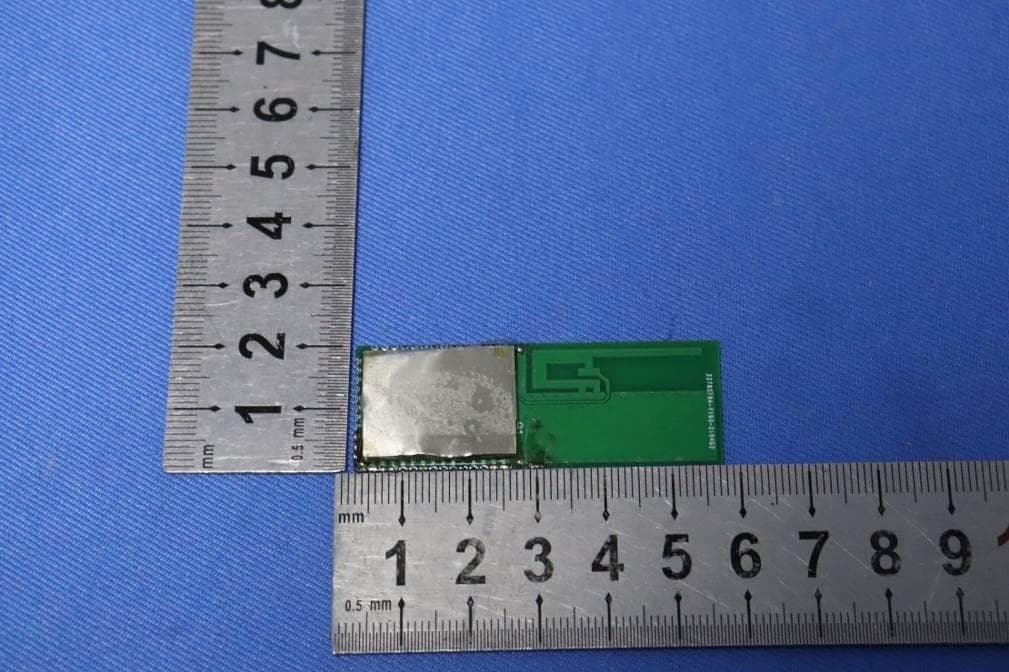
Click to zoom
Application Details
- Equipment Class
- DTS - Digital Transmission System
- Date of Grant
- Jul 24, 2021
- Application Purpose
- Original Equipment
- Date of Application
- Jul 24, 2021
- Equipment Note
- Radio module
- Frequency Range
- 2405.00000000 - 2480.00000000
- Company
- Vulpes d.o.o.
- Country
- Croatia
Documents & Files
Document Text
Text extracted from the exhibit documents filed with the FCC. Open a document above to read the original.
Users Manual
USER MANUAL The CC2538 is the ideal SoC for high- performance ZigBee applications. It combines a powerful ARM Cortex®-M3- based MCU system with up to 32K on-chip RAM and up to 512 K on-chip flash with a robust IEEE 802.15.4 radio. This enables it to handle complex network stacks with security, demanding applications, and over-the-air download. Thirty-two GPIOs and serial peripherals enable simple connections to the rest of the board. The powerful security accelerators enable quick and efficient authentication and encryption while leaving the CPU free to handle application tasks. The low-power modes with retention enable quick startup from sleep and minimum energy spent to perform periodic tasks. For a smooth development, the CC2538xFnn includes a powerful debugging system and a comprehensive driver library. To reduce the application flash footprint, CC2538xFnn ROM includes a utility function library and a serial boot loader. FCC ID: 2AZ89C2538 CC2538 RADIO MODULEE Features & Applications Built in CC2538 SoC 512KB, 256KB or 128KB of In-SystemProgrammable Flash Size: 55 mm x 20 mm Powerful ARM® Cortex®-M3 With Code Prefetch Up to 32-MHz Clock Speed 512KB, 256KB or 128KB of In-SystemProgrammable Flash Supports On-Chip Over-the-Air Upgrade (OTA) Supports Dual ZigBee Application Profiles Up to 32KB of RAM (16KB With Retention in All Power Modes) cJTAG and JTAG Debugging RF 2.4-GHz IEEE 802.15.4 Compliant RF Transceiver Excellent Receiver Sensitivity of –97 dBm Robustness to Interference With ACR of 44 dB Programmable Output Power up to 7 dB Worldwide Acceptance Applicatons Consumer electronics Mobile phone accessories Sports & Fitness equipment HID applications Home and Building Automation, Lighting Control, Alarm and Security Electronic Shelf Labeling, Proximity Tags And many more... Electrical Characteristics ITEM TEST REQUIREMENT REMARKS Active-Mode RX (CPU Idle): 20 mA Active-Mode TX at 0 dBm (CPU Idle): 24 mA Power Mode 1 (4-μs Wake-Up, 32-KB RAM Retention, Full Register Retention): 0.6 mA Power Mode 2 (Sleep Timer Running, 16-KB RAM Retention, Configuration Register Retention): 1.3 μA Power Mode 3 (External Interrupts, 16-KB RAM Retention, Configuration Register Retention): 0.4 μA Wide Supply-Voltage Range (2 V to 3.6 V) Module size 55 mm*20 mm RECOMMENDED OPERATING CONDITIONS Operating ambient temperature range, TA -30 85 °C CAUTION: ESD sensitive device. Precautions should be used when handing the device in order to prevent permanent damage. 55.00 20.00 55.00 1.50 2.50 Pin assignemet NAME Pin PIN TYPE VDD 14,15 GND 10 DVDD_USB 13 Power (USB pads) JTAG_TCK 2 Digital I/O JTAG_TMS 1 Digital I/O PA0 24 Digital/analog I/O PA1 25 Digital/analog I/O PA2 26 Digital/analog I/O PA3 27 Digital/analog I/O PA4 29 Digital/analog I/O PA5 30 Digital/analog I/O PA6 31 Digital/analog I/O PA7 32 Digital/analog I/O PB0 13 Digital I/O PB1 9 Digital I/O PB2 8 Digital I/O PB3 7 Digital I/O PB4 6 Digital I/O PB5 5 Digital I/O PB6 4 Digital I/O PB7 3 Digital I/O PC0 23 Digital I/O PC1 22 Digital I/O PC2 21 Digital I/O PC3 20 Digital I/O PC4 19 Digital I/O PC5 18 Digital I/O PC6 17 Digital I/O PC7 16 Digital I/O PD0 33 Digital I/O PD1 34 Digital I/O PD2 35 Digital I/O PD3 37 Digital I/O PD4 38 Digital I/O PD5 39 Digital I/O RESET_N 36 Digital input USB_P 11 USB I/O USB_N 12 USB I/O Pin countig starts top left. 1 14 39 26 1525 FCC regulatory compliance statement §15.19 Statement This device complies with Part 15 of the FCC Rules. Operation is subject to the follow- ing two conditions: (1) this device may not cause harmful interference, and (2) this device must accept any interference received, including interference that may cause undesired operation. §15.21 Information to user Warning: changes or modifications not expressly approved by the party responsible for compliance could void the user’s authority to operate the equipment. List of applicable FCC rules: 47 CFR Part 15, Subpart C 15.203 47 CFR Part 15, Subpart C 15.205 47 CFR Part 15, Subpart C 15.207 47 CFR Part 15, Subpart C 15.209 47 CFR Part 15, Subpart C 15.247 47 CFR Part 2 2.1091 Summarize the specific operational use conditions This module can be used in IOT devices, the input voltage to the module is nominal- ly 5V. Only the embedded integral antenna is allowed. Any other external antenna is prohibited. Limited module procedures This module is not a limited module. Trace antenna designs The antenna is not a trace antenna. RF exposure considerations This Module complies with FCC radiation exposure limits set forth for an uncontrolled environment. This equipment should be installed and operated with a minimum distance of 20cm between the radiator and your body. This transmitter must not be co-located or operating in conjunction with any other antenna or transmitter. Antennas If you desire to increase antenna gain and either change antenna type or use same antenna type certified, a Class II permissive change application is required to be filed by us, or you (host manufacturer) can take responsibility through the change in FCC ID (new application) procedure followed by a Class II permissive change application. FCC regulatory compliance statement Label and compliance information Please notice that if the FCC identification number is not visible when the module is in- stalled inside another device, then the outside of the device into which the module is installed must also display a label referring to the enclosed module. This exterior label can use wording such as the following: “Contains FCC ID: _2AZ89C2538_” any similar wording that expresses the same meaning may be used. § 15.19 Labelling requirements shall be complied on end user device. Labelling rules for special device, please refer to §2.925, § 15.19 (a)(5) and relevant KDB publications. For E-label, please refer to §2.935. Information on test modes and additional testing requirements The OEM integrator is responsible for ensuring that the end-user has no manual in- struction to remove or insta…
Text truncated - open the document above for the full version.
Cover Letter(s)
Vulpes d.o.o. Date: 2021-6-15 TO: Federal Communication Commission Equipment Authorization Branch 7435 Oakland Mills Road Columbia, MID 21046 Regarding: FCC ID: 2AZ89C2538 To whom it may concern: We, the undersigned, hereby authorize SGS-CSTC Standards Technical Services Co., Ltd. (SGS) Shenzhen Branch and Keny Xu in SGS-CSTC Standards Technical Services Co., Ltd. (SGS) Shenzhen Branch to act on our behalf in all manners relating to application for equipment authorization with respect to the FCC ID above, including signing of all documents relating to these matters. Any and all acts carried out by the agent on our behalf shall have the same effect as acts of our own. We, the undersigned, hereby certify that we are not subject to a denial of federal benefits, that includes FCC benefits, pursuant to Section 5301 of the Anti-Drug Abuse Act of 1988, 21 U.S.C. 853(a). Where our agent signs the application for certification on our behalf, I acknowledge that all responsibilit y for complying with the terms and conditions for Certification, as specified by SGS North America, Inc., still resides with Vulpes d.o.o. This authorization is valid until further written notice from the applicant. Print Name: Hrvoje Lasic Title: B.Sc.Mech.Eng Signature: On behalf of Company: Vulpes d.o.o. Telephone: 0038598450603 E-mail: [email protected], [email protected]
Cover Letter(s)
Vulpes d.o.o. Date: 2021-6-15 To: Federal Communications Commission Office of Engineering and Technology Laboratory Division 7435 Oakland Mills Rd. Columbia MD 21046 From: Vulpes d.o.o. Regarding: Confidentiality Request regarding application for FCC ID: 2AZ89C2538 LONG TERM CONFIDENTIALITY Pursuant to 47 CFR Section 0.459 and 0.457 of the commission’s rules, the applicant hereby requests confidential treatment of the documents listed below, associated with the certification application referenced above. Schematic(s) Block Diagrams Operational Descriptions The documents above contain proprietary information not released to the public. Public disclosure of this information may prove harmful to the business of the applicant. SHORT TERM CONFIDENTIALITY Additionally, the applicant requests the following documents be held confidential until the device is marketed or 180 days from the grant date whichever is less. If the device is marketed within confidential period, the applicant will notify the TCB per FCC KDB 726920 D01 Confidentiality Request Procedures. External Photos Internal Photos Test Setup Photos User manual(s) Print Name: Hrvoje Lasic Title: B.Sc.Mech.Eng Signature: On behalf of Company: Vulpes d.o.o. Telephone: 0038598450603 E-mail: [email protected], [email protected]
Cover Letter(s)
Applicant Declaration Applicant Declaration Rev:0.0 SGS North America Inc. 620 Old Peachtree Road SUITE 100 Suwanee, Georgia 30024 United States Applicant Legal Business Name Vulpes d.o.o. Address Gracanska 120/A Zagreb 10000 Croatia Grantee Code 2AZ89 FCC ID 2AZ89C2538 Authorized Contact Name Hrvoje Lasic Contact Email [email protected] Contact Phone 0038598450603 I, the undersigned, certify that I am an authorized signatory for the Applicant and therefore declare; a) in accordance with 47CFR2.911(d), all of the statements herein and the exhibits attached hereto are true and correct to the best of my knowledge and belief. b) in accepting a Grant of Equipment Authorization issued by a TCB, under the authority of the FCC, as a result of the representations made in this application, the Applicant is responsible for: (1) labeling the equipment with the exact FCC ID as specified in this application, (2) compliance statement labeling pursuant to the applicable rules, (3) compliance of the equipment with the applicable technical rules, c) if the Applicant is not the actual manufacturer of the equipment, appropriate arrangements have been made with the manufacturer to ensure that production units of this equipment will continue to comply with the FCC’s technical requirements. d) in accordance with 47 CFR 2.909 and KDB394321, the Applicant has read, understood and agrees to accept that they are the responsible party and agree to abide by their responsibilities as specified under 47 CFR 2.909 and KDB394321. e) in accordance with ISO17065, FCC KDB641163, FCC KDB610077, KDB394321 and RSP-100, the Applicant has read, understood, accepts and agrees to abide by the post market surveillance requirements. (1) the Applicant understands, accepts and agrees that a sample may be requested for surveillance testing. (2) the Applicant shall make provisions to always have a production sample available upon request by SGS, FCC and/or ISED. (3) the Applicant shall, upon request by SGS, at the Applicant’s expense, provide a production sample of the requested product to SGS, FCC and/or ISED as instructed. The sample shall include all support devices, cables, software, accessories or other hardware or software required for evaluation, review, certification and audit surveillance of products certified by SGS. f) neither the Applicant nor any party to the application is subject to a denial of Federal benefits, that includes FCC benefits, pursuant to Section 5301 of the Anti-Drug Abuse Act of 1988, 21 U.S.C. §862 because of a conviction for possession or distribution of a controlled substance. See 47CFR 1.2002(b) for the definition of a “party” for these purposes. g) the Applicant has read, understood, accepts and agrees to abide by the SGS North America, Inc.(TCB) terms and conditions. Link to CFRs: https://www.fcc.gov/wireless/bureau-divisions/technologies-systems-and-innovation-division/rules-regulations-title-47 Link to KDBs: https://apps.fcc.gov/oetcf/kdb/index.cfm Link to RSP-100: https://www.ic.gc.ca/eic/site/smt-gst.nsf/eng/sf01130.html Applicant Signature: Date: 2021-6-15 Print Name: Hrvoje Lasic Title: B.Sc.Mech.Eng *NOTE: This declaration cannot be signed by an Agent, it shall be signed by an authorized person listed in the FCC database
Cover Letter(s)
Vulpes d.o.o. Modular Approval Request Letter FCC ID: 2AZ89C2538 Dear Examiner, There’s a Radio module that would like to have your authorization as a modular approval. The specific product as below, Radio module with its designed features and specified description, meets special requirements for Single, Limited Single Modular Approval on FCC KDB996369 by cross- reference list below. Requirement of FCC KDB996369 Comply (Y/N) 1. The modular transmitter must have its own RF shielding. Y The EUT provides the RF shielding. See EUT photo. 2. The modular transmitter must have buffered modulation/data inputs (if such inputs are provided) to ensure that the module will comply with Part 15 requirements under conditions of excessive data rates or over-modulation. Y The EUT has its buffered modulation. Please see the Schematic Diagram. 3. The modular transmitter must have its own power supply regulation. Y The EUT has its own power supply regulation, please see the Schematic Diagram. 4. The modular transmitter must comply with the antenna and transmission system requirements of Sections 15.203, 15.204(b) and 15.204(c). The antenna must either be permanently attached or employ a “unique” antenna coupler (at all connections between the module and the antenna, including the cable). The “professional installation” provision of Section 15.203 is not applicable to modules but can apply to limited modular approvals under paragraph (b) of this section. Y The EUT meets the FCC antenna requirements; unique antenna connector and photo of antenna are shown in the test report. 5. The modular transmitter must be tested in a stand- alone configuration, i.e., the module must not be inside another device during testing. Y The EUT was tested with a test board, please see test report and setup photo 6. The modular transmitter must be labeled with its own FCC ID number, and, if the FCC ID is not visible when the module is installed inside another device, then the outside of the device into which the module is installed must also display a label referring to the enclosed module. Y Please see exhibition label sample for the FCC ID of this module. Also in the exhibition Users manual, there are instructions give to the OEM on how to label the end product. 7. The modular transmitter must comply with any specific rule or operating requirements applicable to the transmitter and the manufacturer must provide adequate instructions along with the module to Y The EUT is compliant with all applicable FCC rules. Details instructions for maintaining compliance are give in the Vulpes d.o.o. explain any such requirements. A copy of these instructions must be included in the application for equipment authorization. User Manual. 8. The modular transmitter must comply with any applicable RF exposure requirements. For example, FCC Rules in Sections 2.1091, 2.1093 and specific Sections of Part 15, including 15.319(i),15.407(f),15.253(f)and15.255(g), require that Unlicensed PCS, UNII and millimeter wave device performing routine environmental evaluation for RF Exposure to demonstrate compliance. In addition, spread spectrum Transmitters operating under Section 15.247 are required to address RF Exposure compliance in accordance with Section 15.247(b)(4). Y The EUT complies with RF exposure requirement. Sincerely, Print Name: Hrvoje Lasic Title: B.Sc.Mech.Eng Signature: On behalf of Company: Vulpes d.o.o. Telephone: 0038598450603 E-mail: [email protected], [email protected]
External Photos
SGS-CSTC Standards Technical Services Co., Ltd. Shenzhen Branch Page: 1 of 2 External Photos for SZCR2103020076AT FCC ID: 2AZ89C2538 SGS-CSTC Standards Technical Services Co., Ltd. Shenzhen Branch Page: 2 of 2 1 EUT Constructional Details
ID Label/Location Info
FCC ID: 2AZ89C2538 This device complies with Part 15 of the FCC Rules. Operation is subject to the following two conditions: (1) this device may not cause harmful interference, and (2) this device must accept any interference received, including interference that may cause undesired operation. CC2538 R ADIO MODULE Location: The lable location is on the RF shielding. See EUT photo on page 2.
Internal Photos
SGS-CSTC Standards Technical Services Co., Ltd. Shenzhen Branch Page: 1 of 3 Internal Photos for SZCR2103020076AT FCC ID: 2AZ89C2538 SGS-CSTC Standards Technical Services Co., Ltd. Shenzhen Branch Page: 2 of 3 1 EUT Constructional Details SGS-CSTC Standards Technical Services Co., Ltd. Shenzhen Branch Page: 3 of 3
RF Exposure Info
SGS-CSTC Standards Technical Services Co., Ltd. Shenzhen Branch Report No.: SZCR210302007602 Page: 1 of 7 Keny Xu EMC Laboratory Manager 1 Cover page SAR Evaluation Report Application No.: SZCR2103020076AT Applicant: Vulpes d.o.o. Address of Applicant: Gracanska 120/A Zagreb 10000 Croatia Manufacturer: VULPES DOO Address of Manufacturer: GRACANSKA 120/A, 10000 ZAGREB, CROATIA Factory: VULPES DOO Address of Factory: Milutina Baraca 62, 51000 Rijeka, Croatia Equipment Under Test (EUT): EUT Name: Radio module Model No.: CC2538 RADIO MODULE Trade mark: MUONIO FCC ID: 2AZ89C2538 Standards: 47 CFR Part 1.1307 47 CFR Part 2.1091 Date of Receipt: 2021-03-17 Date of Test: 2021-05-01 to 2021-05-19 Date of Issue: 2021-05-26 Test Result : PASS* * In the configuration tested, the EUT complied with the standards specified above. SGS-CSTC Standards Technical Services Co., Ltd. Shenzhen Branch Report No.: SZCR210302007602 Page: 2 of 7 2 Version Revision Record Version Chapter Date Modifier Remark 01 2021-05-26 Original Authorized for issue by: Bill Chen/Project Engineer Eric Fu/Reviewer SGS-CSTC Standards Technical Services Co., Ltd. Shenzhen Branch Report No.: SZCR210302007602 Page: 3 of 7 3 Contents Page 1 COVER PAGE ........................................................................................................................................ 1 2 VERSION ................................................................................................................................................ 2 3 CONTENTS ............................................................................................................................................ 3 4 GENERAL INFORMATION ..................................................................................................................... 4 4.1 GENERAL DESCRIPTION OF EUT ......................................................................................................... 4 4.2 TEST LOCATION ................................................................................................................................ 5 4.3 TEST FACILITY .................................................................................................................................. 5 4.4 DEVIATION FROM STANDARDS ............................................................................................................ 5 4.5 ABNORMALITIES FROM STANDARD CONDITIONS .................................................................................... 5 4.6 OTHER INFORMATION REQUESTED BY THE CUSTOMER .......................................................................... 5 5 SAR EVALUATION ................................................................................................................................. 6 5.1 RF EXPOSURE COMPLIANCE REQUIREMENT ........................................................................................ 6 5.1.1 Limits .......................................................................................................................................... 6 5.1.2 Test Procedure ........................................................................................................................... 6 SGS-CSTC Standards Technical Services Co., Ltd. Shenzhen Branch Report No.: SZCR210302007602 Page: 4 of 7 4 General Information 4.1 General Description of EUT Power supply: DC in 3.3V Operation Frequency: 2405MHz to 2480MHz Modulation Type: O-QPSK Number of Channels: 16 Channel Spacing: 5MHz Antenna Type: Inverted F Antenna Antenna Gain: 3.3dBi SGS-CSTC Standards Technical Services Co., Ltd. Shenzhen Branch Report No.: SZCR210302007602 Page: 5 of 7 4.2 Test Location All tests were performed at: SGS-CSTC Standards Technical Services Co., Ltd. Shenzhen Branch No. 1 Workshop, M-10, Middle section, Science & Technology Park, Shenzhen, Guangdong, China 518057 Telephone: +86 (0) 755 2601 2053 Fax: +86 (0) 755 2671 0594 No tests were sub-contracted. 4.3 Test Facility The test facility is recognized, certified, or accredited by the following organizations: • A2LA (Certificate No. 3816.01) SGS-CSTC Standards Technical Services Co., Ltd., Shenzhen EMC Laboratory is accredited by the American Association for Laboratory Accreditation(A2LA). Certificate No. 3816.01. • VCCI The 3m Fully-anechoic chamber for above 1GHz, 10m Semi-anechoic chamber for below 1GHz, Shielded Room for Mains Port Conducted Interference Measurement and Telecommunication Port Conducted Interference Measurement of SGS-CSTC Standards Technical Services Co., Ltd. have been registered in accordance with the Regulations for Voluntary Control Measures with Registration No.: G-20026, R-14188, C-12383 and T-11153 respectively. • FCC –Designation Number: CN1178 SGS-CSTC Standards Technical Services Co., Ltd., Shenzhen EMC Laboratory has been recognized as an accredited testing laboratory. Designation Number: CN1178. Test Firm Registration Number: 406779. • Innovation, Science and Economic Development Canada SGS-CSTC Standards Technical Services Co., Ltd., Shenzhen EMC Laboratory has been recognized by ISED as an accredited testing laboratory. CAB identifier: CN0006. IC#: 4620C. 4.4 Deviation from Standards None. 4.5 Abnormalities from Standard Conditions None. 4.6 Other Information Requested by the Customer None. SGS-CSTC Standards Technical Services Co., Ltd. Shenzhen Branch Report No.: SZCR210302007602 Page: 6 of 7 5 SAR Evaluation 5.1 RF Exposure Compliance Requirement 5.1.1 Limits According to FCC Part1.1310: The criteria listed in the following table shall be used to evaluate the environment impact of human exposure to radio frequency (RF) radiation as specified in part1.1307(b) F= Frequency in MHz Friis Formula Friis transmission formula: Pd = (Pout*G)/(4* Pi * R 2) Where Pd = power density in mW/cm2 Pout = output power to antenna in mW G = gain of antenna in linear scale Pi = 3.1416 R = distance between observation point and center of the radiator in cm Pd id the …
Text truncated - open the document above for the full version.
Test Report
SGS-CSTC Standards Technical Services Co., Ltd. Shenzhen Branch Report No.: SZCR210302007601 Page: 1 of 54 Keny Xu EMC Laboratory Manager TEST REPORT Application No.: SZCR2103020076AT Applicant: Vulpes d.o.o. Address of Applicant: Gracanska 120/A Zagreb 10000 Croatia Manufacturer: VULPES DOO Address of Manufacturer: GRACANSKA 120/A, 10000 ZAGREB, CROATIA Factory: VULPES DOO Address of Factory: Milutina Baraca 62, 51000 Rijeka, Croatia Equipment Under Test (EUT): EUT Name: Radio module Model No.: CC2538 RADIO MODULE Trade Mark: MUONIO FCC ID: 2AZ89C2538 Standard(s) : 47 CFR Part 15, Subpart C 15.247 Date of Receipt: 2021-03-17 Date of Test: 2021-05-01 to 2021-05-19 Date of Issue: 2021-05-26 Test Result: Pass* * In the configuration tested, the EUT complied with the standards specified above. SGS-CSTC Standards Technical Services Co., Ltd. Shenzhen Branch Report No.: SZCR210302007601 Page: 2 of 54 Revision Record Version Chapter Date Modifier Remark 01 2021-05-26 Original Authorized for issue by: Bill Chen/Project Engineer Eric Fu/Reviewer SGS-CSTC Standards Technical Services Co., Ltd. Shenzhen Branch Report No.: SZCR210302007601 Page: 3 of 54 2 Test Summary Radio Spectrum Technical Requirement Item Standard Method Requirement Result Antenna Requirement 47 CFR Part 15, Subpart C 15.247 N/A 47 CFR Part 15, Subpart C 15.203 & 15.247(b)(4) Pass Radio Spectrum Matter Part Item Standard Method Requirement Result Conducted Peak Output Power 47 CFR Part 15, Subpart C 15.247 ANSI C63.10 (2013) Section 11.9.1 47 CFR Part 15, Subpart C 15.247(b)(3) Pass Minimum 6dB Bandwidth ANSI C63.10 (2013) Section 11.8.1 47 CFR Part 15, Subpart C 15.247a(2) Pass Power Spectrum Density ANSI C63.10 (2013) Section 11.10.2 47 CFR Part 15, Subpart C 15.247(e) Pass Conducted Band Edges Measurement ANSI C63.10 (2013) Section 11.13.3.2 47 CFR Part 15, Subpart C 15.247(d) Pass Conducted Spurious Emissions ANSI C63.10 (2013) Section 11.11 47 CFR Part 15, Subpart C 15.247(d) Pass Radiated Emissions which fall in the restricted bands ANSI C63.10 (2013) Section 6.10.5 47 CFR Part 15, Subpart C 15.205 & 15.209 Pass Radiated Spurious Emissions Below 1GHz ANSI C63.10 (2013) Section 6.4,6.5 47 CFR Part 15, Subpart C 15.205 & 15.209 Pass Radiated Spurious Emissions Above 1GHz ANSI C63.10 (2013) Section 6.6 47 CFR Part 15, Subpart C 15.205 & 15.209 Pass Emission Part Item Standard Method Requirement Result Conducted Emissions at AC Power Line (150kHz-30MHz) 47 CFR Part 15, Subpart C 15.247 ANSI C63.10 (2013) Section 6.2 47 CFR Part 15, Subpart C 15.207 Pass SGS-CSTC Standards Technical Services Co., Ltd. Shenzhen Branch Report No.: SZCR210302007601 Page: 4 of 54 3 Contents Page 1 COVER PAGE ..................................................................................................................................... 1 2 TEST SUMMARY ................................................................................................................................. 3 3 CONTENTS ......................................................................................................................................... 4 4 GENERAL INFORMATION .................................................................................................................. 6 4.1 DETAILS OF E.U.T. ......................................................................................................................... 6 4.2 DESCRIPTION OF SUPPORT UNITS .................................................................................................... 6 4.3 MEASUREMENT UNCERTAINTY ......................................................................................................... 7 4.4 TEST LOCATION ............................................................................................................................. 8 4.5 TEST FACILITY ............................................................................................................................... 8 4.6 DEVIATION FROM STANDARDS ......................................................................................................... 8 4.7 ABNORMALITIES FROM STANDARD CONDITIONS ................................................................................. 8 5 EQUIPMENT LIST ............................................................................................................................... 9 6 RADIO SPECTRUM TECHNICAL REQUIREMENT ............................................................................11 6.1 ANTENNA REQUIREMENT ................................................................................................................11 6.1.1 Test Requirement: ..................................................................................................................11 7 RADIO SPECTRUM MATTER TEST RESULTS .................................................................................12 7.1 CONDUCTED PEAK OUTPUT POWER ................................................................................................12 7.1.1 E.U.T. Operation .....................................................................................................................12 7.1.2 Test Mode Description ............................................................................................................12 7.1.3 Test Setup Diagram ................................................................................................................12 7.1.4 Measurement Procedure and Data .........................................................................................13 7.2 MINIMUM 6DB BANDWIDTH .............................................................................................................14 7.2.1 E.U.T. Operation .....................................................................................................................14 7.2.2 Test Mode Description .................................................................................................…
Text truncated - open the document above for the full version.
Test Setup Photos
SGS-CSTC Standards Technical Services Co., Ltd. Shenzhen Branch Page: 1 of 3 Setup Photos for SZCR2103020076AT FCC ID: 2AZ89C2538 SGS-CSTC Standards Technical Services Co., Ltd. Shenzhen Branch Page: 2 of 3 1 Photographs Conducted Emissions at AC Power Line (150kHz-30MHz) Radiated Spurious Emissions Below 1GHz SGS-CSTC Standards Technical Services Co., Ltd. Shenzhen Branch Page: 3 of 3 Radiated Spurious Emissions Above 1GHz
Contact Information
Applicant
Hrvoje Lasic
Technical Contact
SGS-CSTC Standards Technical Services Co., Ltd.Keny Xu
[email protected]86-755-25328629
No.1 Workshop, M-10, Middle Section, · Shenzhen · China
Non-Technical Contact
SGS-CSTC Standards Technical Services Co., Ltd.Keny Xu
[email protected]86-755-25328629
Test Firm
SGS-CSTC Standards Technical Services Co., LtdDerek Yang
[email protected]+86 0135 6484 8721
Technical Specifications
| # | Rule Parts | Frequency Range | Power Output |
|---|---|---|---|
| 1 | 15C | 2.40 GHz - 2.48 GHz | 1.20 mW |
Other Applications from Vulpes d.o.o.

2AZ89C2640
Jul 26, 2021Radio module
Equipment Class
DTS - Digital Transmission System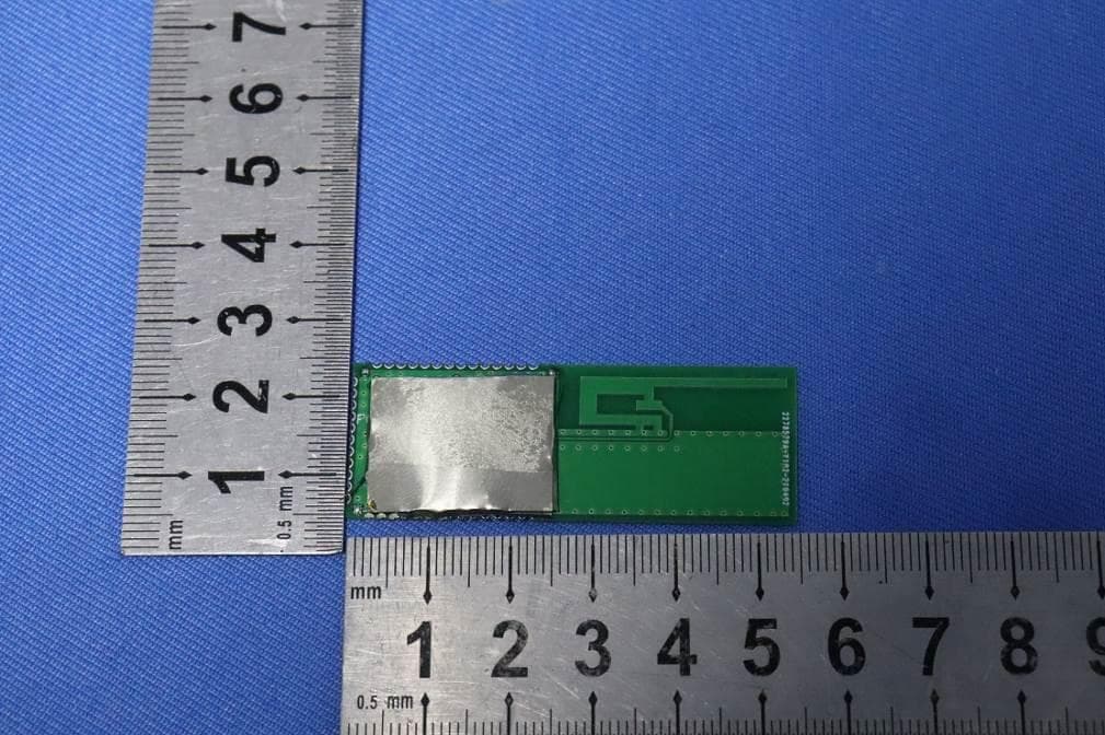
2AZ89C2530
Jul 24, 2021Radio module
Equipment Class
DTS - Digital Transmission System