2AZ8M-BCX620BUSmart Mood Light Soother
Chillax Care Limited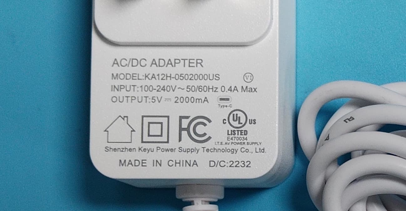
Click to zoom
Application Details
- Equipment Class
- DSS - Part 15 Spread Spectrum Transmitter
- Date of Grant
- Mar 28, 2023
- Application Purpose
- Original Equipment
- Date of Application
- Mar 28, 2023
- Equipment Note
- Smart Mood Light Soother
- Frequency Range
- 2402.00000000 - 2480.00000000
- Company
- Chillax Care Limited
- Country
- Hong Kong
Documents & Files
Document Text
Text extracted from the exhibit documents filed with the FCC. Open a document above to read the original.
Users Manual
USER’S GUIDE Baby Mood Pro 4.3'' Smart Video Monitor with Mood Light Soother MODELS: DM620, DM620-2, DM620-3, DM620-4, DM620BU Welcome... to your new Chillax Wi-Fi ® Video Baby Monitor ! Thank you for purchasing the Wi-Fi ® Video Baby Monitor. Now you can see and hear your baby sleeping. Our Connected Baby Monitor let you see your baby from the hand-held viewer, or from your smartphone. Watch over and communicate with your baby from anywhere in the world. Please keep your original dated sales receipt for your records. For warranty service of your Chillax product, you will need to provide a copy of your dated sales receipt to confirm warranty status. Registration is not required for warranty coverage. For questions, warranty, support or service related to the product, please contact us by: Email: [email protected] Or, visit us at http://chillaxcare.com This User’s Guide has all the information you need to make the most out of your product. Please read the Safety Instructions on pages 8-9 before you install the unit. Inside the Box • 1 x Parent Unit (with built-in Li-ion battery) • 1 x Giraffe Camera • 1 x Sleep Globe (Mood Light Soother with built-in Li-ion battery) • 2 x Power Adapters (Parent Unit and Baby Unit) • 1 x User Guide In multi-camera packs, you will find one or more additional Camera Units with power adapters. Overview of Parent Unit 1 2 4101112 5 6 7 8 9 3 13 1. Display (LCD screen) 2. Parent Unit ON/OFF Long press to switch on when unit is off. Long press to switch off when unit is on. Short press to turn LCD screen Off when unit is on. 3. Audio Level LEDs (Green, Green, Amber, Red, Red) 4. MENU button Pr ess to open / close the Menu options. 5. Zoom button Toggle to zoom in/out the image in 1x and 2x ratios. 6. OK button 7. Navigation buttons + - < > Move Left < /Right > to control the sl eep globe pan movement in viewing mode. Move Up + /Down - /Rig ht > / Left < menu options. 8. Brightness button Press to adjust the LCD brightness level (up to 8 levels) with Left / Right buttons. 9. 2-Way Talk button Press and hold to speak to your baby. 10. Volume +/- Adjust the speaker volume level by pressing + or - buttons. 11. Diapering log button Press and hold to record one diaper change event. 12. Feeding log button Press and hold to record one feeding event. 13. Power Socket Parent unit menu icons Signal Level (5 Levels). Night Vision Mode (Video also changes to Black/White). Talk Mode On. Indicates the screen off timer is set. Set Screen Off Timer (Off, 5 mins, 30 mins, 60 mins). Volume Level Control (8 Levels). No Baby Unit detected. Battery Level Indication (4 Levels). Zoom Level Control (1X, 2X). LCD Brightness Level Control (8 Levels). Alarm Setting (6h, 4h, 2h, OFF) On status bar, indicates alarm set, and when flashing, that alarm time has been reached or missed. Temperature scales select (°C/°F) Readings display in BLUE, but turn RED if > 29 °C / 84 °F or <14 °C / 57 °F. Displays LL °C / °F if < 1 °C / 34 °F. Displays HH °C / °F if >36 °C / 97 °F. Camera Control (scan , view , add , del ). View multiple cameras on screen. Available when you have more than 1 Baby Unit (Camera). Sleep Globe mood light color selection. Sleep Globe setting Mood light brightness control (up to 3 levels). Speaker volume control (up to 8 levels). Overview of Baby Unit Important guidelines for installing your Digital Video Baby Monitor • To use your Baby Unit and Parent Unit together, you must be able to establish a radio link between them, and the range will be affected by environmental conditions. • Any large metal object, like a refrigerator, a mirror, a filing cabinet, a metallic door or reinforced concrete, between the Baby Unit and Parent Unit may block the radio signal. • The signal strength may also be reduced by other solid structures, like walls, or by radio or electrical equipment, such as TVs, computers, cordless or mobile phones, fluorescent lights or dimmer switches. • Other 2.4GHz products, such as wireless networks (Wi-Fi ® routers), Bluetooth™ systems, microwave ovens or other Baby Monitors, may cause interference with this product, so keep the Baby Monitor at least 5ft (1.5m) away from these types of products, or switch them off if they appear to be causing interference. • If the signal is weak, try moving the Parent and/or the Baby Unit to different positions in the rooms. 1 6 7 4 5 13 17 14 15 16 2 12 11 10 9 3 3 8 7 1. Light Sensor 2. Camera Lens 3. Privacy Protection Knob Sli de to switch On/Off the privacy protection mode. 4. Mood Light Globe 5. Gooseneck 6. PAIR Button 7. Micro-SD Card Slot Support micro-SD card up to 32MB memory. 8. Touch Sense Control 9. Power ON/OFF Switch 10. + Button Press to increase speaker volume (5 levels). 11. – Button Press to decrease speaker volume (5 levels). 12. Room Temperature Sensor 13. USB-A Socket 14. Mood Light Brightness Button Press once to adjust the brightness level from 1 to 5 in cyclic. 15. PAIR Button 16. USB-C Power Socket 17. Power LED 6 Table of contents 1. Safety Instructions ..........................................................................................8 2. Getting Started ............................................................................................10 2.1 Plugging the Giraffe Cam to the Sleep Globe (Mood Light Soother) .........................................................................10 2.2 Connecting the Power Supply for the Baby Unit ...........................11 2.3 Power On or Off the Baby Unit .........................................................11 2.4 Connecting the Power Supply of the Parent Unit ..........................12 2.5 Desktop Stand of the Parent Unit .....................................................13 2.6 Registration (Pairing) ..........................................................................13 3. Using the Baby Monitor ...............................................................................14 3.1 SD Card Installation...........................…
Text truncated - open the document above for the full version.
External Photos
Shenzhen Accurate Technology Co., Ltd. FCC ID: 2AZ8M-BCX620BU External Photos Page 1 of 8 Shenzhen Accurate Technology Co., Ltd. FCC ID: 2AZ8M-BCX620BU External Photos Page 2 of 8 Shenzhen Accurate Technology Co., Ltd. FCC ID: 2AZ8M-BCX620BU External Photos Page 3 of 8 Shenzhen Accurate Technology Co., Ltd. FCC ID: 2AZ8M-BCX620BU External Photos Page 4 of 8 Adapter 1 Shenzhen Accurate Technology Co., Ltd. FCC ID: 2AZ8M-BCX620BU External Photos Page 5 of 8 Shenzhen Accurate Technology Co., Ltd. FCC ID: 2AZ8M-BCX620BU External Photos Page 6 of 8 Adapter 2 Shenzhen Accurate Technology Co., Ltd. FCC ID: 2AZ8M-BCX620BU External Photos Page 7 of 8 Shenzhen Accurate Technology Co., Ltd. FCC ID: 2AZ8M-BCX620BU External Photos Page 8 of 8
ID Label/Location Info
Shenzhen Accurate Technology Co., Ltd. Project No.: RA221213-61312E-RF LABEL AND LOCATION Page 1 of 1 FCC ID Label FCC ID Label Location Information The label shown shall be permanently affixed at a conspicuous location on the device and be readily visible to the user at the time purchase (Labeling requirements per 2.925)
Internal Photos
Shenzhen Accurate Technology Co., Ltd. FCC ID: 2AZ8M-BCX620BU Internal Photos Page 1 of 10 Internal photos Shenzhen Accurate Technology Co., Ltd. FCC ID: 2AZ8M-BCX620BU Internal Photos Page 2 of 10 Shenzhen Accurate Technology Co., Ltd. FCC ID: 2AZ8M-BCX620BU Internal Photos Page 3 of 10 Shenzhen Accurate Technology Co., Ltd. FCC ID: 2AZ8M-BCX620BU Internal Photos Page 4 of 10 Shenzhen Accurate Technology Co., Ltd. FCC ID: 2AZ8M-BCX620BU Internal Photos Page 5 of 10 Shenzhen Accurate Technology Co., Ltd. FCC ID: 2AZ8M-BCX620BU Internal Photos Page 6 of 10 Shenzhen Accurate Technology Co., Ltd. FCC ID: 2AZ8M-BCX620BU Internal Photos Page 7 of 10 Shenzhen Accurate Technology Co., Ltd. FCC ID: 2AZ8M-BCX620BU Internal Photos Page 8 of 10 Shenzhen Accurate Technology Co., Ltd. FCC ID: 2AZ8M-BCX620BU Internal Photos Page 9 of 10 Shenzhen Accurate Technology Co., Ltd. FCC ID: 2AZ8M-BCX620BU Internal Photos Page 10 of 10 Antenna 2.4G FHSS Antenna 2.4G Wi-Fi Antenna
RF Exposure Info
Shenzhen Accurate Technology Co., Ltd. Report No.: RA221213-61312E-RFB Version 30: 2021-11-09 Page 12 of 49 FCC&RSS-FHSS FCC §15.247 (i) & §1.1307 (b) (3) & §2.1091- MPE-Based Exemption Applicable Standard According to subpart 15.247 (i) and subpart 2.1091 systems operating under the provisions of this section shall be operated in a manner that ensures the public is not exposed to RF energy level in excess of the communication guidelines. According to KDB 447498 D04 Interim General RF Exposure Guidance MPE-Based Exemption: General frequency and separation-distance dependent MPE-based effective radiated power(ERP) thresholds are in Table B.1 [Table 1 of § 1.1307(b)(1)(i)(C)] to support an exemptionfrom further evaluation from 300 kHz through 100 GHz. Ris the minimum separation distance in meters f = frequency in MHz Result Mode Frequency (MHz) Tune up conducted power Antenna GainERP Evaluation Distance (m) ERP Limit (mW) (dBm) (dBi) (dBd)(dBm)(mW) FHSS 2402-24808.0 0 -2.15 5.85 3.846 0.2 768 Note: 1. The tune up conducted power and antenna gain was declared by the applicant. 2. The FHSS and Wi-Fi cannot transmit at same time. To maintain compliance with the FCC’s RF exposure guidelines, place the equipment at least 20cm from nearby persons. Result: Compliant.
Test Report
Manufacture:Chillax Care Limited Room 118, Flat A, 8/F, William Industrial Building, 23-25 Ng Fong Street, San Po Kong, Kowloon, Hong Kong Antenna Specification 1. TECHNICAL SPECIFICATION Antenna Type Monopole Company Name Chillax Care Limited Model: H6 Frequency Range 2.4G FHSS: 2402-2480MHz 2.4G Wi-Fi: 2412-2472MHz Antenna Gain 2.4G FHSS: 0dBi 2.4G Wi-Fi: 0dBi 2.4G FHSS Antenna: Freq[MHz] Gain(dBi) 2400 -0.1 2410 -0.2 2420 -0.4 2430 -0.3 2440 0 2450 -0.1 2460 -0.2 2470 -0.1 2780 -0.5 Radiation pattern@2402MHz +X +Y +Z Radiation pattern@2440MHz +X +Y +Z Radiation pattern@2480MHz +X +Y +Z 2.4G Wi-Fi Antenna: Freq[MHz] Gain(dBi) 2400 -0.3 2410 -0.4 2420 -0.1 2430 -0.5 2440 -0.2 2450 -0.1 2460 0 2470 -0.3 2780 -0.6 2400MHz 2440MHz 2500MHz
Test Report
★ Note: This report may contain data that are not covered by the A2LA accreditation and are marked with an asterisk “ ”. Shenzhen Accurate Technology Co., Ltd. is not responsible for the authenticity of any test data provided by the applicant. Data included from the applicant that may affect test results are marked with an asterisk ’*’. Customer model name, addresses, names, trademarks etc. are not considered data. This report cannot be reproduced except in full, without prior written approval of the Company. Unless otherwise stated the results shown in this test report refer only to the sample(s) tested. This report is valid only with a valid digital signature. The digital signature may be available only under the Adobe software above version 7.0. Shenzhen Accurate Technology Co., Ltd. 1/F., Building A, Changyuan New Material Port, Science & Industry Park, Nanshan District, Shenzhen, Guangdong, P.R. China Tel: +86 755-26503290 Fax: +86 755-26503396 Web: www.atc-lab.com Version 30: 2021-11-09 Page 1 of 49 FCC&RSS-FHSS TEST REPORT Applicant Name : Chillax Care Limited Address : Room 118, Flat A, 8/F, William Industrial Building, 23-25 Ng Fong Street, San Po Kong, Kowloon, Hong Kong Report Number : RA221213-61312E-RFB FCC ID: 2AZ8M-BCX620BU IC: 27169-BCX620BU Test Standard (s) FCC PART 15.247; RSS-GEN ISSUE 5, FEBRUARY 2021 AMENDMENT 2; RSS-247, ISSUE 2, FEBRUARY 2017 Sample Description Product Type: Smart Mood Light Soother Model No.: DM620BU Multiple Model(s) No.: N/A Trade Mark: ChillaxBaby Date Received: 2022/12/13 Report Date: 2023/02/09 Test Result: Pass* * In the configuration tested, the EUT complied with the standards above. Prepared and Checked By: Approved By: Andy Yu Candy Li EMC Engineer EMC Engineer Shenzhen Accurate Technology Co., Ltd. Report No.: RA221213-61312E-RFB Version 30: 2021-11-09 Page 2 of 49 FCC&RSS-FHSS TABLE OF CONTENTS DOCUMENT REVISION HISTORY ......................................................................................................................... 4 GENERAL INFORMATION ....................................................................................................................................... 5 PRODUCT DESCRIPTION FOR EQUIPMENT UNDER TEST (EUT) ..................................................................................... 5 OBJECTIVE ................................................................................................................................................................... 5 TEST METHODOLOGY .................................................................................................................................................. 5 MEASUREMENT UNCERTAINTY .................................................................................................................................... 6 TEST FACILITY ............................................................................................................................................................. 6 SYSTEM TEST CONFIGURATION .......................................................................................................................... 7 DESCRIPTION OF TEST CONFIGURATION ...................................................................................................................... 7 EUT EXERCISE SOFTWARE .......................................................................................................................................... 7 SPECIAL ACCESSORIES ................................................................................................................................................. 7 EQUIPMENT MODIFICATIONS ....................................................................................................................................... 7 SUPPORT EQUIPMENT LIST AND DETAILS .................................................................................................................... 7 EXTERNAL I/O CABLE .................................................................................................................................................. 8 BLOCK DIAGRAM OF TEST SETUP ................................................................................................................................ 8 SUMMARY OF TEST RESULTS ............................................................................................................................... 9 TEST EQUIPMENT LIST ......................................................................................................................................... 10 FCC §15.247 (I) & §1.1307 (B) (3) & §2.1091- MPE-BASED EXEMPTION ............................................................ 12 APPLICABLE STANDARD ............................................................................................................................................ 12 RESULT ...................................................................................................................................................................... 12 RSS-102 § 2.5.2 –EXEMPTION LIMITS FOR ROUTINE EVALUATION-RF EXPOSURE EVALUATION 13 APPLICABLE STANDARD ............................................................................................................................................ 13 FCC §15.203 & RSS-GEN §6.8– ANTENNA REQUIREMENT ............................................................................ 14 APPLICABLE STANDARD ............................................................................................................................................ 14 ANTENNA CONNECTOR CONSTRUCTION .................................................................................................................... 14 FCC §15.207 (A) & RSS-GEN §8.8 – AC LINE CONDUCTED EMISSIONS ...................................................... 15 APPLICABLE STANDARD .........................................................................................................…
Text truncated - open the document above for the full version.
Test Setup Photos
Shenzhen Accurate Technology Co., Ltd. Project No.: RA221213-61312E-RF Test Photos Page 1 of 4 Adapter 1(Model: YWK-AD050200-U): Photo of Conducted Emission Measurement Shenzhen Accurate Technology Co., Ltd. Project No.: RA221213-61312E-RF Test Photos Page 2 of 4 Photo of Radiated Emission Measurement (Below 1G) Photo of Radiated Emission Measurement (Above 1G) Shenzhen Accurate Technology Co., Ltd. Project No.: RA221213-61312E-RF Test Photos Page 3 of 4 Adapter 2(Model: KA12H-0502000US): Photo of Conducted Emission Measurement Shenzhen Accurate Technology Co., Ltd. Project No.: RA221213-61312E-RF Test Photos Page 4 of 4 Photo of Radiated Emission Measurement (Below 1G)
Contact Information
Applicant
Doris Lum(Administration Officer)
Test Firm
Shenzhen Accurate Technology Co., Ltd.Lisa Zhang
[email protected]+86-755-26503290
Technical Specifications
| # | Rule Parts | Frequency Range | Power Output |
|---|---|---|---|
| 1 | 15C | 2.40 GHz - 2.48 GHz | 6.00 mW |
Other Applications from Chillax Care Limited
2AZ8M-XTRA2355
Jun 18, 2026Digital Cordless Telephone
Equipment Class
PUB - Part 15 Unlicensed PCS Base Station