2AZBU-SM651RXBaby Monitor
Shenzhen Mingchuangzhilian Technology Co., Ltd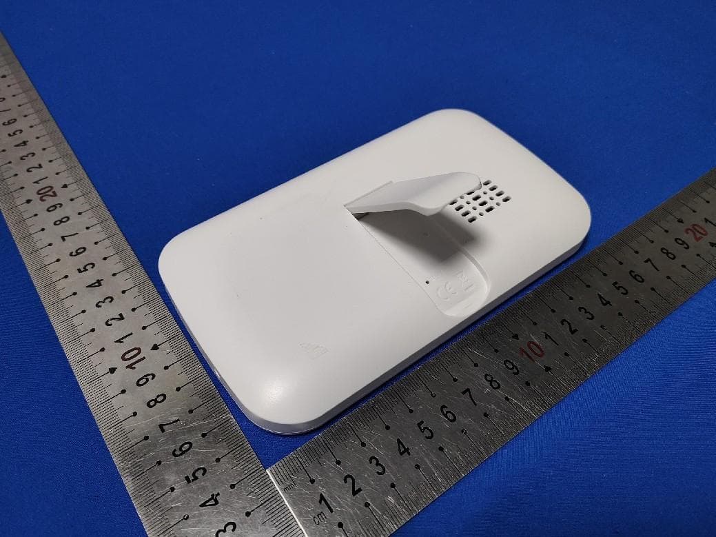
Click to zoom
Application Details
- Equipment Class
- DTS - Digital Transmission System
- Date of Grant
- Aug 30, 2022
- Application Purpose
- Original Equipment
- Date of Application
- Aug 30, 2022
- Equipment Note
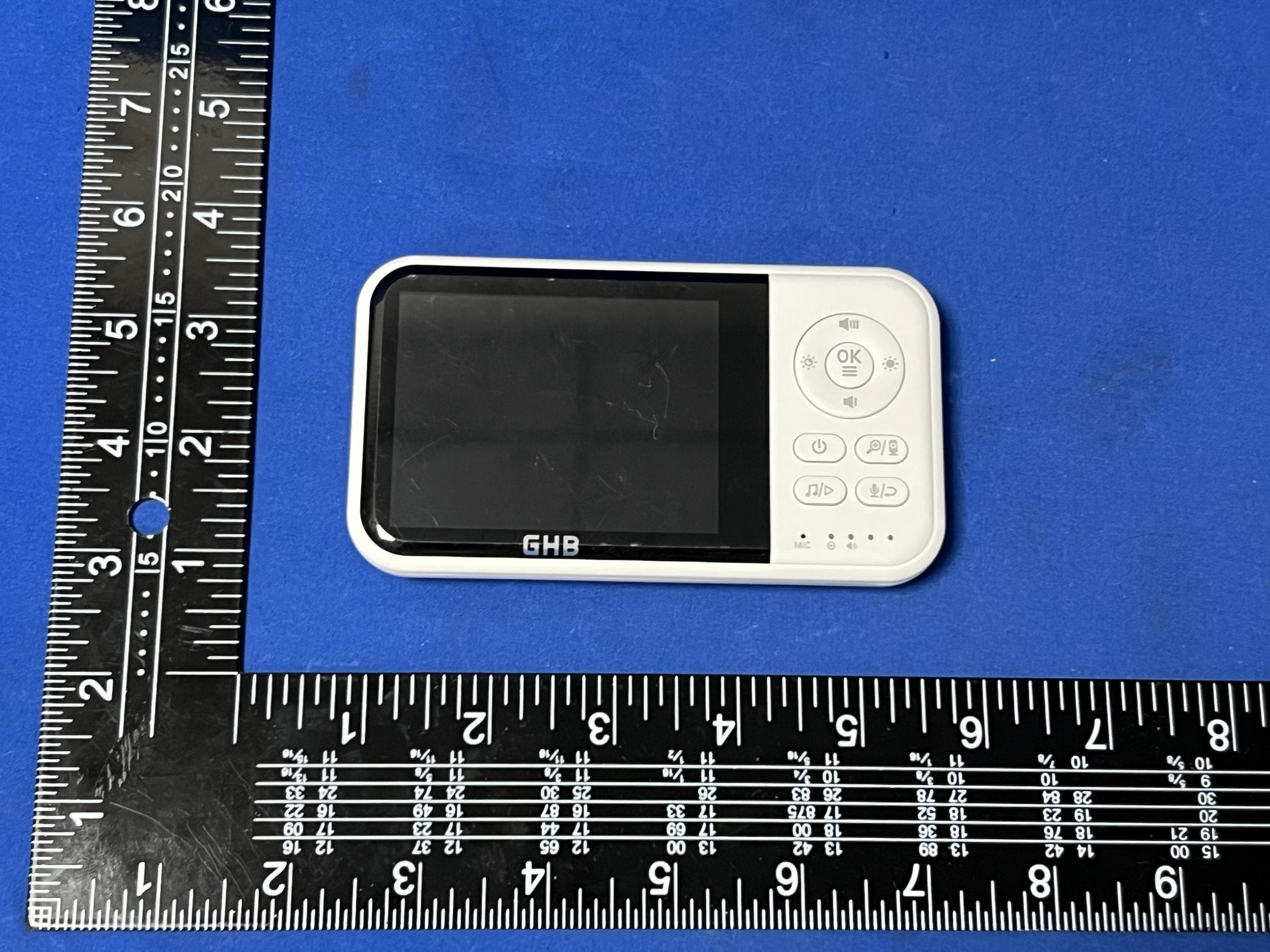
- Baby Monitor
- Frequency Range
- 2410.00000000 - 2477.00000000
- Country
- China
Documents & Files
Document Text
Text extracted from the exhibit documents filed with the FCC. Open a document above to read the original.
Users Manual
size: 128.5x94 mm [email protected] [email protected] [email protected] 1. SAFETY INSTRUCTIONS 1-2 2. PRODUCT OVERVIEW 3 2.1 Package list 3 2.2 Parent unit(monitor) 4-5 2.3 Baby unit(camera) 6 2.4 Icon overview 6 3. USING THE BABY MONITOR 7-10 4. FUNCTION OVERVIEW 11 4.1 Pairing the camera and monitor 11 4.2 Delete the camera 12 4.3 Lullaby setting 13 4.4 Feeding timer setting 14-15 4.5 Vox setting 16-17 4.6 Temperature settings 18 4.6.1 Temperature alarm setting 18 4.6.2 Temperature Hi/Lo alert limits 19 4.7 Setting 20 4.7.1 Language setting 20 4.7.2 Frequecy setting 21 4.7.3 Reset setting 22 5. TECHNICAL DATA 23 5.1 System general 23 6. TROUBLE SHOOTING 24-25 FCC STATEMENTS 26 CONTENT [email protected] [email protected] [email protected] [email protected] Power key: Long press to turn on/o the monitor; short press to screen on/o. Pan/Tilt Press the key to enter into the pan/Tilt mode. Volume + / Up key: Press Volume+ to increase the volume/ To up the camera in the Pan/Tilt mode. Brightness + / Right key: Press the Brightness+ to increase the brightness/ To right the camera in the Pan/Tilt mode. OK: Press the OK key to view/scan camera or to conrm. Volume - / Down key: Press Volume- to decrease the volume/ To down the camera in the Pan/Tilt mode. Brightness - / Left key: Press the Brightness- to decrease the brightness/ To left the camera in the Pan/Tilt mode. Talk to baby: *To talk, press and hold the talk key on the front of the monitor; release to turn it o. 1 3 2 5 4 6 7 8 [email protected] 1 3 5 2 4 6 7 8 9 *Bear in mind that you can't listen to your baby while you're talking to them; to listen to it, you will have to stop pressing this button. Menu/Exit: Press short Menu/Exit key the menu will pop up, and press again to EXit. Press and hold the Menu/Exit key around 2 seconds to operate Zoom in/out. MIC: When talking to the baby, collect the voices of the parents. Power&Charging Indicator LED: *The LED shows red when charging under the display is turn o state. *The LED displays shows orange when charging under the turn on state. *The LED displays shows green after the battery is fully charged. Volume LED: When the baby unit detects the voice, the indicator light will be on, The louder the detected sound, the more lights will light up. LCD screen: Display the baby's picture and the adjustment of each button function. Speaker: Hear the sound from the baby. Stand: Monitor placement stand. Reset key (under the stand): Long press the reset button with a pin to reset the display. DC-jack: Charge the monitor by connecting the Power Adapter to the monitor and a socket. Note: If you want to adjust the Volume/Brightness, you have to exit the Pan/Tilt mode before you operate it. 9 [email protected] VOX Light sensor Speaker infrared LEDs Pair key CMOS sensor DC-Jack Power LED Temperature sensor MIC Antenna 1 8 3 9 2 5 4 6 7 1 3 2 5 4 8 8 9 6 7 8 0 [email protected] 3.1 CHARGING AND POWERING THE MONITOR UNIT Step1: Charge the monitor by connecting the A/C adapter included in this package to the monitor and a socket. (It takes about 4 hours for the monitor to be fully charged). Step2: Use the provided AC adapter included in this package to connect the wall outlet with the baby unit. Charging: Red/orange Fully charged: Green [email protected] Note: *Place the camera at least 3ft / 1m away from your baby. Gently press and hold the Power Button for 3s to turn on the monitor, then you can see the live view. *Follow your needs to adjust the sound, brightness, and reasonable placement of the camera. Tips: To use the baby monitor, you must be able to establish a radio link between the monitor and camera, and the range will be aected by environmental conditions: *Any large metal object, like a refrigerator, a mirror, a ling cabinet, metallic doors or reinforced concrete between the baby and parent unit may block the radio signal. *The signal strength may also be reduced by other solid structures, like walls, or by radio or electrical equipment, such as TV, computers, cordless or mobile phones, uorescent lights or dimmer switches. *When using the other 2.4GHz product, such as wireless networks (Wi-Fi routers), Bluetooth systems, or microwave ovens, may cause interference with this product, so keep the baby monitor away at least 5ft(1.5m) from these types of products. [email protected] [email protected] Step1. Press and hold the Menu/Exit key arond 2 seconds enter Zoom mode. Step2. At the Zoom mode, press the Pan/Tilt key to adjust the direction of the camera/image. Step3. Press the LEFT key to pan left; Press RIGHT key to pan right; Press UP key to tilt up; Press Down key to tilt down. Step4. Press and hold the Menu/Exit key again around 2 seconds to operate Zoom out. During digital zoom mode, the zoom icon will be displayed on the top of screen. Warm reminder: If you want to adjust the Volume/Brightness, you have to exit the Pan/Tilt(press Pan/Tilt key) mode before you operate it. [email protected] 4.FUNCTION OVERVIEW 4.1 PAIRING THE CAMERA AND MONITOR Step1: Press Menu / Exit key and the menu will pop up. Step2: Select the camera icon and press OK key to enter into sub-menu, press the LEFT key or RIGHT key to select the camera to be paired. Step3: Press OK key to start the pairing. While the screen shows pairing then press the PAIR button on the back of camera. Step4: Once paired, then the screen will display the image from the camera. Step5: If unsuccessful, please repeat above steps. VOX MENU Camera 7 Pairing [email protected] 7 VOX MENU Camera Pairing Unpair NOYES [email protected] 4.3 LULLABY SETTING You can soothe the baby to sleep by playing a gentle lullaby from the baby unit. Step1: Press Menu / Exit key and the menu will pop up. Step2: Select the lullaby icon and press OK key to enter into sub-menu. Step3: Press the NAVIGATION key to select the lullaby you need. Step4: Press OK key to conrm. Step5: Press the Menu / Exit key to Exit. Lullaby 1 3 54 2 VOX…
Text truncated - open the document above for the full version.
Cover Letter(s)
Date:04/17/2018VCB_F-01:OperatingProceduresForm–FCCConfidentialityv02Page1of1 ShenzhenMingchuangzhilianTechnologyCo.,Ltd Federal Communications Commission Authorization and Evaluation Division Confidentiality Request regarding application for certification of FCC ID: 2AZBU- SM651RX Pursuant to Sections 0.457 and 0.459 of the Commission’s Rules, we hereby request confidential treatment of information accompanying this application as outlined below: ExhibitType 1.BlockDiagram, 2.Schematics, 3.OperationalDescription File Name 1. 2AZBU-SM651RX-Block diagram 2. 2AZBU-SM651RX-SCH 3. 2AZBU-SM651RX-Operational description Theabovematerialscontaintradesecretsandproprietaryinformationnotcustomarily releasedtothepublic.Thepublicdisclosureofthesematerialsmaybeharmfultothe applicantandprovideunjustifiedbenefitstoitscompetitors. TheapplicantunderstandsthatpursuanttoSection0.457oftheRules,disclosureofthis applicationandallaccompanyingdocumentationwillnotbemadebeforethedateofthe Grantforthisapplication. PursuanttoDA04-1705June15,2004oftheCommission’spublicnotice,wealso requesttemporaryconfidentialtreatmentofinformationaccompanyingthisapplication asoutlinedbelowforaninitialperiodofxxxx(ie-“45”,“90”or“180”)days: ExhibitTypeFileName N/AN/A Signature: Contactname:SambShuai Companyname:ShenzhenMingchuangzhilianTechnologyCo.,Ltd Address: 4/F,BBlock,No.3,EastRegion,ShangxueSciencePark,BantianSt,LonggangDist, Shenzhen,China
Cover Letter(s)
Date:04/17/2018VCB_F-01:OperatingProceduresForm–FCCAuthorizationv02Page1of1 Shenzhen Mingchuangzhilian Technology Co., Ltd Federal Communications Commission Authorization and Evaluation Division 1435 Oakland Mills Road Columbia, MD 21046 Date: 2022-5-19 SUBJECT: FCC Application for (FCC ID:2AZBU-SM651RX) To Whom It May Concern: We, the undersigned, hereby authorizeYoyo Zhouin Shenzhen Huaxia Testing TechnologyCo.,Ltdat1F.,BlockAofTongshengTechnologyBuilding,HuahuiRoad, DalangStreet,LonghuaDistrict,Shenzhen,Chinaonourbehalf,toapplytotheFederal CommunicationsCommissiononourequipment.Anyandallactscarriedoutby ShenzhenHuaxiaTestingTechnologyCo.,Ltd onourbehalfshallhavethesame effectasactsofourown. ThisistoadvisethatweareinfullcompliancewiththeAnti-DrugAbuseAct.We, theapplicant,arenotsubjecttoadenialoffederalbenefitspursuanttoSection 5301oftheAnti-DrugActof1988,21USC853a,andnopartytotheapplicationis subjecttoadenialoffederalbenefitspursuanttothatsection. Sincerely, (MustbesignedbythepersonthatislistedontheFCCWebsite) Signature: Contactname:SambShuai Companyname:ShenzhenMingchuangzhilianTechnologyCo.,Ltd Address:4/F,BBlock,No.3,EastRegion,ShangxueSciencePark,BantianSt,LonggangDist,Shenzhen,China
Cover Letter(s)
We, (Shenzhen Mingchuangzhilian Technology Co., Ltd) certify the product: Baby Monitor Model No.:SM651RX, SM650, SM651, SM652, SM662, SM935C, SM936C , SM672, SM432, SM660, SM662, SM663, SM664, SM665, SM666 ShenzhenMingchuangzhilianTechnologyCo.,Ltd ModelConfirmationLetter Theirelectrical circuit design, layout, components used and internal wiring were identical for the above models, with difference being color of appearance and model name. Signiture: GranteeContact:SambShuai CompanyName:ShenzhenMingchuangzhilianTechnologyCo.,Ltd Date:2022-5-19
External Photos
Externalphotos 1
Internal Photos
Internalphotos
Parts List/Tune Up Info
2AZBU-SM651RX_Tune Up Procedure Measurement Procedure: 1. Set the device to operational voltage and on a predefined channel in a special test mode. 2. The actual output power is measured at several power levels. 3. The gain factors of each individual device are adjusted until the target value is met. The appropriate gain control settings for each output power level are stored in each device individually (for each power level). The user has no possibility to change these settings later on. 4. The maximum gains of each individual device are adjusted and measured until the target value is met. The production target power with tolerance compiles with the maximum power in test report. Average Power Output: Mode 2.4G custom Channel Low Mid High GFSK(1Mbps) 10±1dBm 10±1dBm 11±1dBm Then these appropriate rated RF output power settings are stored in each device individually. The user has no possibility to change these settings later on, and during manufacturing each device will be individual calibrated. The measurement is done in fully calibrated setup, which is based on the base station simulator. Furthermore, the highest power level is verified afterwards in a call measurement on three channels(low, middle and high).
Parts List/Tune Up Info
2AZBU-SM651TX _Tune Up Procedure Measurement Procedure: 1. Set the device to operational voltage and on a predefined channel in a special test mode. 2. The actual output power is measured at several power levels. 3. The gain factors of each individual device are adjusted until the target value is met. The appropriate gain control settings for each output power level are stored in each device individually (for each power level). The user has no possibility to change these settings later on. 4. The maximum gains of each individual device are adjusted and measured until the target value is met. The production target power with tolerance compiles with the maximum power in test report. Rated RF power output: Mode 2.4G GFSK 17±1dBm Then these appropriate rated RF output power settings are stored in each device individually. The user has no possibility to change these settings later on, and during manufacturing each device will be individual calibrated. The measurement is done in fully calibrated setup, which is based on the base station simulator. Furthermore, the highest power level is verified afterwards in a call measurement on three channels(low, middle and high).
Test Report
ShenzhenHuaxiaTestingTechnologyCo.,Ltd. 1F.,BlockAofTongshengTechnologyBuilding,HuahuiRoad,DalangStreet,LonghuaDistrict, Shenzhen,China Telephone:+86-755-26648640 Fax:+86-755-26648637 Website:www.cqa-cert.com ReportTemplateVersion:V05 ReportTemplateRevisionDate:2021-11-03 TestReport Thetestreportiseffectiveonlywithbothsignatureandspecializedstamp,Theresult(s)showninthisreportreferonly tothesample(s)tested.WithoutwrittenapprovalofCQA,thisreportcan’tbereproducedexceptinfull. ReportNo.:CQASZ20220500812E Applicant: ShenzhenMingchuangzhilianTechnologyCo.,Ltd AddressofApplicant: 4/F,BBlock,No.3,EastRegion,ShangxueSciencePark,BantianSt,Longgang Dist,Shenzhen,China EquipmentUnderTest(EUT): Product:BabyMonitor ModelNo.:SM651RX,SM650,SM651,SM652,SM662,SM935C,SM936C,SM672, SM432,SM660,SM662,SM663,SM664,SM665,SM666 TestModelNo.:SM651RX BrandName:N/A FCCID:2AZBU-SM651RX Standards:47CFRPart15,SubpartC DateofReceipt:2021-06-17 DateofTest: 2021-06-17to2022-06-22 DateofIssue:2022-07-04 TestResult:PASS* *Intheconfigurationtested,theEUTcompliedwiththestandardsspecifiedabove. TestedBy: (LewisZhou) ReviewedBy: (KLiao) ApprovedBy: (JackAi) ShenzhenHuaxiaTestingTechnologyCo.,Ltd. ReportNo.:CQASZ20220500812E Page: 2 of 46 1Version RevisionHistoryOfReport ReportNo.Version Description IssueDate CQASZ20220500812ERev.01Initialreport2022-07-04 ShenzhenHuaxiaTestingTechnologyCo.,Ltd. ReportNo.:CQASZ20220500812E Page: 3 of 46 2TestSummary TestItemTestRequirementTestmethodResult AntennaRequirement 47CFRPart15,SubpartCSection 15.203/15.247(c) ANSIC63.102013PASS ACPowerLine Conducted Emission 47CFRPart15,SubpartCSection 15.207 ANSIC63.102013PASS ConductedPeakOutput Power 47CFRPart15,SubpartCSection 15.247(b)(3) ANSIC63.102013PASS 6dBOccupied Bandwidth 47CFRPart15,SubpartCSection 15.247(a)(2) ANSIC63.102013PASS PowerSpectralDensity 47CFRPart15,SubpartCSection 15.247(e) ANSIC63.102013PASS Band-edgeforRF ConductedEmissions 47CFRPart15,SubpartCSection 15.247(d) ANSIC63.102013PASS RFConductedSpurious Emissions 47CFRPart15,SubpartCSection 15.247(d) ANSIC63.102013PASS RadiatedSpurious Emissions 47CFRPart15,SubpartCSection 15.205/15.209 ANSIC63.102013PASS Restrictedbandsaround fundamentalfrequency (RadiatedEmission) 47CFRPart15,SubpartCSection 15.205/15.209 ANSIC63.102013PASS ShenzhenHuaxiaTestingTechnologyCo.,Ltd. ReportNo.:CQASZ20220500812E Page: 4 of 46 3Contents Page 1VERSION..........................................................................................................................................................................2 2TESTSUMMARY............................................................................................................................................................3 3CONTENTS......................................................................................................................................................................4 4GENERALINFORMATION...........................................................................................................................................5 4.1CLIENTINFORMATION.................................................................................................................................................5 4.2GENERALDESCRIPTIONOFEUT.................................................................................................................................5 4.3ADDITIONALINSTRUCTIONS........................................................................................................................................7 4.4TESTENVIRONMENT...................................................................................................................................................8 4.5DESCRIPTIONOFSUPPORTUNITS...............................................................................................................................8 4.6STATEMENTOFTHEMEASUREMENTUNCERTAINTY....................................................................................................9 4.7TESTLOCATION........................................................................................................................................................10 4.8TESTFACILITY..........................................................................................................................................................10 4.9DEVIATIONFROMSTANDARDS..................................................................................................................................10 4.10OTHERINFORMATIONREQUESTEDBYTHECUSTOMER..........................................................................................10 4.11EQUIPMENTLIST.....................................................................................................................................................11 5TESTRESULTSANDMEASUREMENTDATA.....................................................................................................12 5.1ANTENNAREQUIREMENT..........................................................................................................................................12 5.2CONDUCTEDEMISSIONS............................................................................................................................................13 5.3CONDUCTEDPEAKOUTPUTPOWER..........................................................................................................................17 5.46DBOCCUPYBANDWIDTH........................................................................................................................................20 5.5POWERSPECTRALDENSITY......................................................................................................................................23 5.6BAND-EDGEFORRFCONDUCTEDEMISSIONS..........................................................................................................26 5.7SPURIOUSRFCONDUCTEDEMISSIONS..............................................................................…
Text truncated - open the document above for the full version.
Test Report
ShenzhenHuaxiaTestingTechnologyCo.,Ltd. ReportNo.:CQASZ20220500812E Page: 31 of 46 2.4Gcustom_Ant1_2441.501_30~1000 2.4Gcustom_Ant1_2441.501_1000~26500 ShenzhenHuaxiaTestingTechnologyCo.,Ltd. ReportNo.:CQASZ20220500812E Page: 32 of 46 2.4Gcustom_Ant1_2477.001_0~Reference 2.4Gcustom_Ant1_2477.001_30~1000 ShenzhenHuaxiaTestingTechnologyCo.,Ltd. ReportNo.:CQASZ20220500812E Page: 33 of 46 2.4Gcustom_Ant1_2477.001_1000~26500 Remark: Pretest9kHzto25GHz,findthehighestpointwhentesting,soonlytheworstdatawereshowninthetest report.PerFCCPart15.33(a)and15.31(o),Theamplitudeofspuriousemissionsfromintentionalradiators whichareattenuatedmorethan20dBbelowthepermissiblevalueneednotbereportedunlessspecifically requiredelsewhereinthispart. ShenzhenHuaxiaTestingTechnologyCo.,Ltd. ReportNo.:CQASZ20220500812E Page: 34 of 46 5.8RadiatedSpuriousEmission&Restrictedbands 5.8.1SpuriousEmissions TestRequirement:47CFRPart15CSection15.209and15.205 TestMethod:ANSIC63.102013 TestSite:MeasurementDistance:3m(Semi-AnechoicChamber) ReceiverSetup: FrequencyDetectorRBWVBWRemark 0.009MHz-0.090MHzPeak10kHz30kHzPeak 0.009MHz-0.090MHzAverage10kHz30kHzAverage 0.090MHz-0.110MHzQuasi-peak10kHz30kHzQuasi-peak 0.110MHz-0.490MHzPeak10kHz30kHzPeak 0.110MHz-0.490MHzAverage10kHz30kHzAverage 0.490MHz-30MHzQuasi-peak10kHz30kHzQuasi-peak 30MHz-1GHzQuasi-peak100kHz300kHzQuasi-peak Above1GHz Peak1MHz3MHzPeak Peak1MHz10HzAverage Limit: Frequency Fieldstrength (microvolt/meter) Limit (dBuV/m) Remark Measurement distance(m) 0.009MHz-0.490MHz2400/F(kHz)--300 0.490MHz-1.705MHz24000/F(kHz)--30 1.705MHz-30MHz30--30 30MHz-88MHz10040.0Quasi-peak3 88MHz-216MHz15043.5Quasi-peak3 216MHz-960MHz20046.0Quasi-peak3 960MHz-1GHz50054.0Quasi-peak3 Above1GHz50054.0Average3 Note:15.35(b),Unlessotherwisespecified,thelimitonpeakradio frequencyemissionsis20dBabovethemaximumpermittedaverageemission limitapplicabletotheequipmentundertest.Thispeaklimitappliestothetotal peakemissionlevelradiatedbythedevice. ShenzhenHuaxiaTestingTechnologyCo.,Ltd. ReportNo.:CQASZ20220500812E Page: 35 of 46 TestSetup: Figure1.Below30MHz Figure2.30MHzto1GHzFigure3.Above1GHz TestProcedure:a.1)Below1G:TheEUTwasplacedonthetopofarotatingtable0.8 metersabovethegroundata3metersemi-anechoiccamber.Thetable wasrotated360degreestodeterminethepositionofthehighest radiation. 2)Above1G:TheEUTwasplacedonthetopofarotatingtable1.5 metersabovethegroundata3metersemi-anechoiccamber.Thetable wasrotated360degreestodeterminethepositionofthehighest radiation. Note:Fortheradiatedemissiontestabove1GHz: PlacethemeasurementantennaawayfromeachareaoftheEUT determinedtobeasourceofemissionsatthespecifiedmeasurement distance,whilekeepingthemeasurementantennaaimedatthesource ofemissionsateachfrequencyofsignificantemissions,withpolarization orientedformaximumresponse.Themeasurementantennamayhave tobehigherorlowerthantheEUT,dependingontheradiationpatternof theemissionandstayingaimedattheemissionsourceforreceivingthe maximumsignal.Thefinalmeasurementantennaelevationshallbethat whichmaximizestheemissions.Themeasurementantennaelevation formaximumemissionsshallberestrictedtoarangeofheightsoffrom 1mto4mabovethegroundorreferencegroundplane. b.TheEUTwasset3metersawayfromtheinterference-receiving antenna,whichwasmountedonthetopofavariable-heightantenna tower. c.Theantennaheightisvariedfromonemetertofourmetersabovethe groundtodeterminethemaximumvalueofthefieldstrength.Both 1 5 0 c m ShenzhenHuaxiaTestingTechnologyCo.,Ltd. ReportNo.:CQASZ20220500812E Page: 36 of 46 horizontalandverticalpolarizationsoftheantennaaresettomakethe measurement. d.Foreachsuspectedemission,theEUTwasarrangedtoitsworstcase andthentheantennawastunedtoheightsfrom1meterto4meters(for thetestfrequencyofbelow30MHz,theantennawastunedtoheights1 meter)andtherotatabletablewasturnedfrom0degreesto360 degreestofindthemaximumreading. e.Thetest-receiversystemwassettoPeakDetectFunctionandSpecified BandwidthwithMaximumHoldMode. f.IftheemissionleveloftheEUTinpeakmodewas10dBlowerthanthe limitspecified,thentestingcouldbestoppedandthepeakvaluesofthe EUTwouldbereported.Otherwisetheemissionsthatdidnothave10dB marginwouldbere-testedonebyoneusingpeak,quasi-peakor averagemethodasspecifiedandthenreportedinadatasheet. g.TesttheEUTinthelowestchannel(2410.001MHz),themiddlechannel (2441.501MHz),theHighestchannel(2480MHz) h.TheradiationmeasurementsareperformedinX,Y,Zaxispositioning forTransmittingmode,andfoundtheXaxispositioningwhichitisthe worstcase. i.Repeataboveproceduresuntilallfrequenciesmeasuredwascomplete. ExploratoryTest Mode: TransmittingwithGFSKmodulation. Transmittingmode. FinalTestMode:ThroughPre-scan,findthe1MbpsofdatatypeandGFSKmodulationisthe worstcase. Forbelow1GHzpart,throughpre-scan,theworstcaseisthehighest channel. Onlytheworstcaseisrecordedinthereport. TestResults:Pass ShenzhenHuaxiaTestingTechnologyCo.,Ltd. ReportNo.:CQASZ20220500812E Page: 37 of 46 RadiatedEmissionbelow1GHz 30MHz~1GHz,theworstcase Testmode:TransmittingmodeHorizontal ShenzhenHuaxiaTestingTechnologyCo.,Ltd. ReportNo.:CQASZ20220500812E Page: 38 of 46 30MHz~1GHz,theworstcase Testmode:TransmittingmodeVertical ShenzhenHuaxiaTestingTechnologyCo.,Ltd. ReportNo.:CQASZ20220500812E Page: 39 of 46 TransmitterEmissionabove1GHz Worsecasemode:GFSK(1Mbps)Testchannel:Lowest Frequency Meter Reading Factor Emission Level LimitsOver Detector Type Ant.Pol. (MHz)(dBμV)(dB)(dBμV/m)(dBμV/m)(dB) H/V 239053.51-9.244.3174-29.69PeakH 240055.25-9.3945.8674-28.14PeakH 4820.00252.58-4.3348.2574-25.75PeakH 720648.281.0149.2974-24.71PeakH 239054.90-9.245.7074-28.30PeakV 240053.05-9.3943.6674-30.34PeakV 4820.00254.30-4.3349.9774-24.03PeakV 720649.511.0150.5274-23.48PeakV Worsecasemode:GFSK(1Mbps)Testchannel:Middle Frequency Meter ReadingFactor Emission LevelLimitsOver Detector TypeAnt.Pol. (MHz)(dBμV)(dB)(dBμV/m)(dBμV/m)(dB) H/V 4883.00252.37-4.1148.2674-25.74peakH 7324.50349.251.5150.7674-23.24peakH 4883.00252.05-4.1147.9474-26.06peakV 7324.50351.191.5152.7074-21.30peakV Worsecasemode:GFSK(1Mbps)Testchannel:Highest Frequency Meter Read…
Text truncated - open the document above for the full version.
Test Report
ShenzhenHuaxiaTestingTechnologyCo.,Ltd. 1F.,BlockAofTongshengTechnologyBuilding,HuahuiRoad,DalangStreet,LonghuaDistrict, Shenzhen,China Telephone:+86-755-26648640 Fax:+86-755-26648637 Website:www.cqa-cert.com ReportTemplateVersion:V05 ReportTemplateRevisionDate:2021-11-03 TestReport Thetestreportiseffectiveonlywithbothsignatureandspecializedstamp,Theresult(s)showninthisreportreferonly tothesample(s)tested.WithoutwrittenapprovalofCQA,thisreportcan’tbereproducedexceptinfull. ReportNo.:CQASZ20220500812E Applicant: ShenzhenMingchuangzhilianTechnologyCo.,Ltd AddressofApplicant: 4/F,BBlock,No.3,EastRegion,ShangxueSciencePark,BantianSt,Longgang Dist,Shenzhen,China EquipmentUnderTest(EUT): Product:BabyMonitor ModelNo.:SM651RX,SM650,SM651,SM652,SM662,SM935C,SM936C,SM672, SM432,SM660,SM662,SM663,SM664,SM665,SM666 TestModelNo.:SM651RX BrandName:N/A FCCID:2AZBU-SM651RX Standards:47CFRPart15,SubpartC DateofReceipt:2021-06-17 DateofTest: 2021-06-17to2022-06-22 DateofIssue:2022-07-04 TestResult:PASS* *Intheconfigurationtested,theEUTcompliedwiththestandardsspecifiedabove. TestedBy: (LewisZhou) ReviewedBy: (KLiao) ApprovedBy: (JackAi) ShenzhenHuaxiaTestingTechnologyCo.,Ltd. ReportNo.:CQASZ20220500812E Page: 2 of 47 1Version RevisionHistoryOfReport ReportNo.Version Description IssueDate CQASZ20220500812ERev.01Initialreport2022-07-04 ShenzhenHuaxiaTestingTechnologyCo.,Ltd. ReportNo.:CQASZ20220500812E Page: 3 of 47 2TestSummary TestItemTestRequirementTestmethodResult AntennaRequirement 47CFRPart15,SubpartCSection 15.203/15.247(c) ANSIC63.102013PASS ACPowerLine Conducted Emission 47CFRPart15,SubpartCSection 15.207 ANSIC63.102013PASS ConductedPeakOutput Power 47CFRPart15,SubpartCSection 15.247(b)(3) ANSIC63.102013PASS 6dBOccupied Bandwidth 47CFRPart15,SubpartCSection 15.247(a)(2) ANSIC63.102013PASS PowerSpectralDensity 47CFRPart15,SubpartCSection 15.247(e) ANSIC63.102013PASS Band-edgeforRF ConductedEmissions 47CFRPart15,SubpartCSection 15.247(d) ANSIC63.102013PASS RFConductedSpurious Emissions 47CFRPart15,SubpartCSection 15.247(d) ANSIC63.102013PASS RadiatedSpurious Emissions 47CFRPart15,SubpartCSection 15.205/15.209 ANSIC63.102013PASS Restrictedbandsaround fundamentalfrequency (RadiatedEmission) 47CFRPart15,SubpartCSection 15.205/15.209 ANSIC63.102013PASS ShenzhenHuaxiaTestingTechnologyCo.,Ltd. ReportNo.:CQASZ20220500812E Page: 4 of 47 3Contents Page 1VERSION..........................................................................................................................................................................2 2TESTSUMMARY............................................................................................................................................................3 3CONTENTS......................................................................................................................................................................4 4GENERALINFORMATION...........................................................................................................................................5 4.1CLIENTINFORMATION.................................................................................................................................................5 4.2GENERALDESCRIPTIONOFEUT.................................................................................................................................5 4.3ADDITIONALINSTRUCTIONS........................................................................................................................................7 4.4TESTENVIRONMENT...................................................................................................................................................8 4.5DESCRIPTIONOFSUPPORTUNITS...............................................................................................................................8 4.6STATEMENTOFTHEMEASUREMENTUNCERTAINTY....................................................................................................9 4.7TESTLOCATION........................................................................................................................................................10 4.8TESTFACILITY..........................................................................................................................................................10 4.9DEVIATIONFROMSTANDARDS..................................................................................................................................10 4.10OTHERINFORMATIONREQUESTEDBYTHECUSTOMER..........................................................................................10 4.11EQUIPMENTLIST.....................................................................................................................................................11 5TESTRESULTSANDMEASUREMENTDATA.....................................................................................................12 5.1ANTENNAREQUIREMENT..........................................................................................................................................12 5.2CONDUCTEDEMISSIONS............................................................................................................................................13 5.3CONDUCTEDPEAKOUTPUTPOWER..........................................................................................................................17 5.46DBOCCUPYBANDWIDTH........................................................................................................................................20 5.5POWERSPECTRALDENSITY......................................................................................................................................23 5.6BAND-EDGEFORRFCONDUCTEDEMISSIONS..........................................................................................................26 5.7SPURIOUSRFCONDUCTEDEMISSIONS..............................................................................…
Text truncated - open the document above for the full version.
Test Report
SmartreeTechnologyCO.,Ltd AntennaInformation ManufacturerSmartreeTechnologyCO.,Ltd AntennaType2.4Gbuilt-inmetalantenna AntennaModelST650RX-24L-ANT-V01 AntennaPartNumberJ7 AntennaFrequencyRange 2400-2483(MHZ) AntennaInputPowerLimitation 1W AntennaPeakGain1.0 AntennaDimension(LxHxW (dBi) )20.5*8.5*1(mm) AntennaPhoto AntennaTopView[WithRuler] AntennaBottomView[WithRuler] CompanyLet…
Text truncated - open the document above for the full version.
Contact Information
Applicant
Samb Shuai
Test Firm
Shenzhen Huaxia Testing Technology Co., LtdJack Ai
[email protected]+8613902988375
Technical Specifications
| # | Rule Parts | Frequency Range | Power Output |
|---|---|---|---|
| 1 | 15C | 2.41 GHz - 2.48 GHz | 16.90 mW |
Other Applications from Shenzhen Mingchuangzhilian Technology Co., Ltd
2AZBU-632BPU
Mar 23, 2026Baby Monitor
Equipment Class
DSS - Part 15 Spread Spectrum Transmitter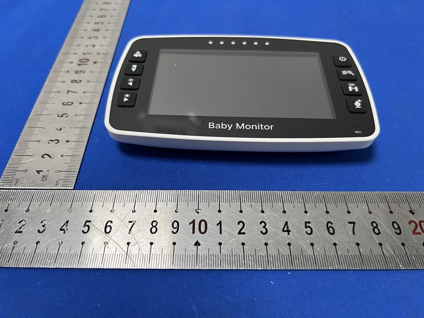
2AZBU-43RX
Feb 13, 2023Baby Monitor
Equipment Class
DSS - Part 15 Spread Spectrum Transmitter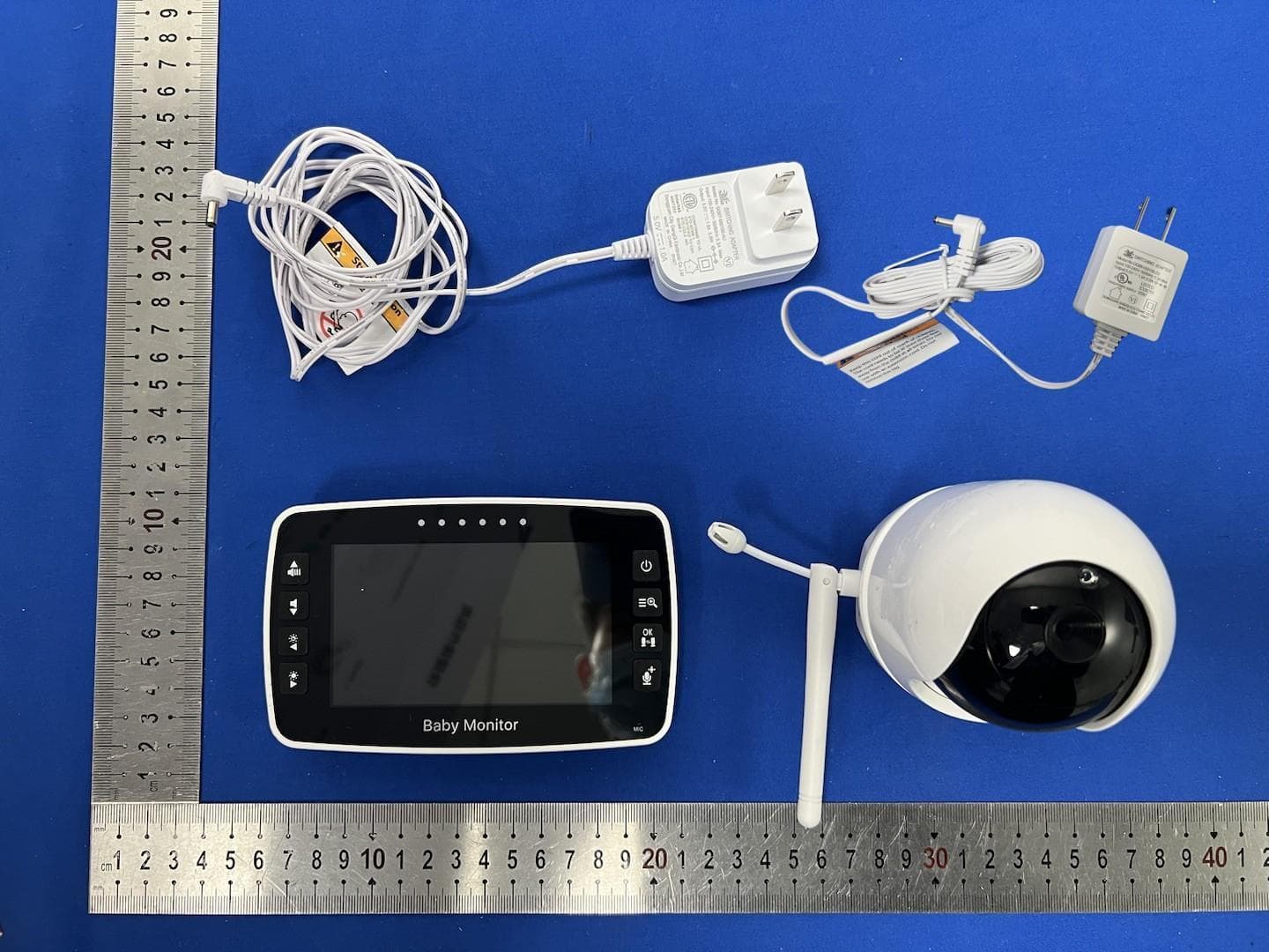
2AZBU-43ATX
Feb 05, 2023Baby Monitor
Equipment Class
DSS - Part 15 Spread Spectrum Transmitter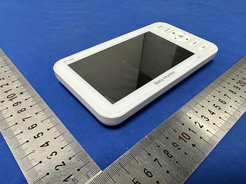
2AZBU-50B
Nov 09, 2022Baby Monitor
Equipment Class
DTS - Digital Transmission System
2AZBU-SM510RX
Jun 08, 2022Baby Monitor
Equipment Class
DSS - Part 15 Spread Spectrum Transmitter