Text extracted from the exhibit documents filed with the FCC. Open a document above to read the original.
User Manual | Manual de usuario | Manuel d’utilisateur Alloy Magnetic Wireless Charger IMPORTANT English NOTE: This charger is designed for Qi-compatible devices. If your phone does not have built-in Qi wireless charging capabilities, please use a certified Qi wireless charging case or receiver. Refer to your phone’s user manual for detailed features and functions. Phone cases that contain metal, magnets, or are thicker than 3mm will interfere with wireless charging. X NO Metal X NO Thick Case IMPORTANT English Output 15W/10W/7.5W/5W Wireless Charger USB-C Cable You can also use MagSafe Charger with other phone models that support wireless charging. This charger magnetically snaps to the back of an iPhone 12 or to its MagSafe case or sleeve (sold separately) and aligns iPhone properly, allowing you to hold and use iPhone while it’s charging. 1.5m 5ft INSTRUCTIONS English Plug the USB-C connector to a 20W PD or greater USB-C power adapter or compatible third-party USB-C adapter (9V/2.22A or 9V/2.56A and higher). *charger sold separately. NOTE: You can also connect to a USB-C port on a Mac or PC. The charger will also function with power adapters that provide a minimum 12W (5V/2.4A) of power, but this will result in slower charging. INSTRUCTIONS English iPhone 12 models Place the charger on the back of the iPhone or its MagSafe case or sleeve. When the iPhone starts charging, the green charging symbol appears. Other phones Place the phone face up on the center of the charger. When the phone is aligned properly with the charger, the Battery Charging icon appears in the status bar. NOTE: If an iPhone Leather Wallet is attached, remove it before placing the charger on the back of the case. Standby Charging Foreign Object Detected It’s normal for a wireless charger and your device to become warm while charging. Need help? Visit www.naztech.com for additional product information or contact [email protected] Read all safety instructions and warnings prior to using this product. Improper use and failure to follow safety guidelines could result in hazards, injury and/or property damage that is not the manufacturer’s responsibility. The user is responsible for maintaining this product with care for maximum use. Contact [email protected] to submit a warranty claim. Proof of purchase is required 1. Do not place metal objects, magnets, magnetic stripe cards, and hard drive based devices near the wireless charger. It may cause data corruption. 2. Do not attempt to modify, disassemble, or repair this product. 3. Do not expose to water, moisture, or extreme temperatures (below 40°F or above 90°F). 4. Under any circumstances, if you find this product rapidly increasing in temperature, emitting odor, or demonstrating an abnormal phenomenon, discontinue use immediately. IMPORTANT English IMPORTANTE Español NOTA: Este cargador está diseñado para dispositivos compatibles con Qi. Si su telĂ©fono no tiene capacidades de carga inalámbrica Qi incorporadas, use un receptor o estuche de carga inalámbrica certificada Qi. Consulte el manual del usuario de su telĂ©fono para conocer las caracterĂsticas y funciones detalladas. Los estuches del telĂ©fono que contienen metal, imanes o tienen un grosor superior a 3mm interferirán con la carga inalámbrica. X NO Metal X NO Estuche grueso IMPORTANTE Español Salida 15W/10W/7.5W/5W Cargador inalámbrica Cable USB-C TambiĂ©n puedes usar el cargador con otros modelos de telĂ©fono compatibles con carga inalámbrica. El cargador se adjunta de forma magnĂ©tica a la parte posterior del iPhone 12 o a una funda MagSafe (se vende por separado) y se ajusta correctamente, lo que permite agarrar y usar el iPhone mientras se recarga. 1.5m 5ft INSTRUCCIONES Español Enchufe el conector USB-C a un adaptador de corriente USB-C de 20W PD o superior o un adaptador USB-C certificado de tercero (9V/2.22A o 9V/2.56A y superior). *cargador se vende separadamente NOTA: TambiĂ©n puede conectarse a un puerto USB-C en una Mac o PC. El cargador tambiĂ©n funcionará con adaptadores de corriente que proporcionen un mĂnimo de 12W (5V/2.4A) de poder, pero esto resultará en una carga más lenta. INSTRUCCIONES Español Modelos de iPhone 12 Coloca el cargador MagSafe en la parte posterior del iPhone o de su funda MagSafe. Cuando el iPhone comience a recargarse, se mostrará el sĂmbolo verde de recarga. Otros telĂ©fonos Coloca el telĂ©fono boca arriba en el centro del cargador. Cuando el telĂ©fono está alineado correctamente con el cargador, el Ăcono de recarga de la baterĂa aparece en la barra de estado. NOTA: Si el iPhone tiene la cartera de piel, quĂtala antes de colocar el cargador en la parte posterior de la funda. Listo Carga Objeto extraño detectado Es normal que un cargador inalámbrico y su dispositivo se calienten durante la carga. ÂżNecesita ayuda? Visite www.naztech.com para obtener informaciĂłn adicional sobre el producto o pĂłngase en contacto con [email protected] Lea todas las instrucciones de seguridad y advertencias antes de usar este producto. El uso incorrecto y el incumplimiento de las normas de seguridad podrĂan provocar peligros, lesiones, y/o daños materiales los cuales no son parte de la responsabilidad del fabricante. El usuario es responsable de mantener este producto con precauciĂłn para máximo utilizaciĂłn. GarantĂa limitada de por vida. PĂłngase en contacto con info@naztech. com para someter una reclamaciĂłn de garantĂa. Se requiere una prueba de compra. 1. No coloque materiales extraños, como objetos metálicos, imanes y tarjetas con banda magnĂ©tica, entre el dispositivo mĂłvil y el cargador inalámbrico. Puede causar daños en los datos. 2. No intente modificar, desmontar o reparar este producto. 3. No exponga al agua, humedad, o temperaturas extremas (por debajo de 40°F o por encima de 90°F). 4. Si encuentra este producto aumentando rápidamente de temperatura, emitiendo olor, deformado, erosionado o mostrando un fenĂłmeno anormal, descontinĂşe el uso inmediatamente. IMPORTANTE Español IMPORTANT Français REMARQUE: …
Text truncated - open the document above for the full version.
HANK ELECTRONICS VIETNAM LTD Office of Engineering Technology Federal Communications Commission 7435 Oakland Mills Road Columbia, MD 21046 USA Date: 03/24/2021 Subject; Request for Confidentiality FCC ID: 2AZCV-WP1851M To Whom It May Concern, Pursuant to the provisions of the Commission’s rules Title 47 Sections §0.457 and §0.459, we are requesting the Commission to withhold the following attachment(s) as confidential documents from public disclosure indefinitely. These documents contain detailed system and equipment descriptions and are considered as proprietary information in operation of the equipment. The public disclosure of these documents might be harmful to our company and would give competitors an unfair advantage in the market. Schematic Diagram Block Diagram Parts List Operational Description Tune-up Procedure Software Security Requirement In additional to above mentioned documents, in order to comply with the marketing regulations in Title 47 CFR §2.803 and the importation rules in Title 47 CFR §2.1204, while ensuring that business sensitive information remains confidential until the actual marketing of newly authorized devices, we request Short Term Confidentiality of the following attachment(s); External Photos Test Setup Photos Internal Photos User Manual For 45 days, pursuant to Public Notice DA 04-1705. OR For 180 days pursuant to KDB 726920 D01. It is our understanding that all measurement test reports, FCC ID label format and correspondence during the certification review process cannot be granted as confidential documents and this information will be available for public review once the grant of equipment authorization is issued. Sincerely, Signature: Wen Cheng Title: Certification Engineer
HANK ELECTRONICS VIETNAM LTD Letter of Authorization Company: HANK ELECTRONICS VIETNAM LTD Address: No.7, 11 Street VSIP Tu Son, 16353 Bac Ninh Province, Vietnam Product Name: WIRELESS CHARGER Model Number: HKWP1851M-15E FCC Identifier: 2AZCV-WP1851M We authorize MiCOM LabsInc, 575 Boulder Court, Pleasanton, California94566, USA, to act on our behalf on all matters concerning the above named equipment. Any individual within MiCOM Labs is authorized to act on our behalf and take action on the application. We declare that MiCOM LabsInc, 575 Boulder Court, Pleasanton, California 94566, USA, is allowed to forward all information related to the approval project to the Federal Communication Commission and to discuss any issues concerning the approval application. Any and all acts carried out by MiCOM Labs on our behalf shall have the same effect as acts of our own. Name: Wen Cheng Date: 2021-03-24 Title: Certification Engineer Signature of applicant
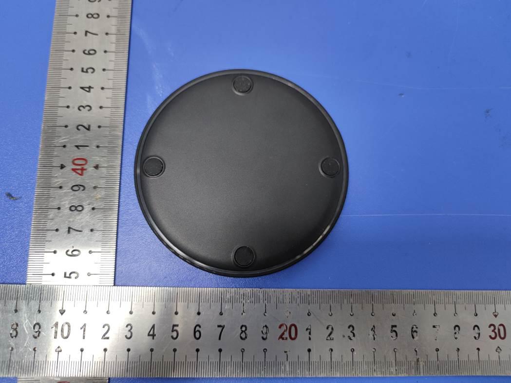
FCC ID: 2AZCV-WP1851M TB-RF-075-1.0 Appendix III EUT External Photographs Photo 1 Appearance of EUT Photo 2 Appearance of EUT FCC ID: 2AZCV-WP1851M TB-RF-075-1.0 Photo 3 Appearance of EUT Photo 4 Appearance of EUT FCC ID: 2AZCV-WP1851M TB-RF-075-1.0 Photo 5 Appearance of EUT
FCC ID: 2AZCV-WP1851M TB-RF-07 4-1.0 Appendix IFCC ID Label Size for the label: 10mm X 10mm FCC ID: 2AZCV-WP1851M Model: HKWP1851M-15E This device complies with Part 15 of the FCC Rules. Operation is subject to the following two conditions: 1. This device may not cause harmful interference, and 2. This device must accept any interference received, including interference that may cause undesired operation. FCC ID: 2AZCV-WP1851M TB-RF-075-1.0 Appendix II ID Label Location ID LOCATION 8
FCC ID: 2AZCV-WP1851M TB-RF-075-1.0 Appendix IV EUT Internal Photographs Photo 6 Internal of EUT Photo 7 Internal of EUT FCC ID: 2AZCV-WP1851M TB-RF-075-1.0 Photo 8 Appearance of PCB Photo 9 Appearance of PCB Antenna
Shenzhen Toby Technology Co., Ltd. Report No.: TB-MPE179018 Page: 1 of 6 TB-RF-074-1.0 1/F.,Building 6, Rundongsheng Industrial Zone, Longzhu, Xixiang,Bao'an District, Shenzhen, Guangdong, China Tel: +86 75526509301 Fax: +86 75526509195 RF Exposure Evaluation FCC ID: 2AZCV-WP1851M 1. Client Information Applicant : HANK ELECTRONICS VIETNAM LTD Address : No.7, 11 Street VSIP Tu Son, 16353 Bac Ninh Province, Vietnam Manufacturer : HANK ELECTRONICS VIETNAM LTD Address : No.7, 11 Street VSIP Tu Son, 16353 Bac Ninh Province, Vietnam 2. General Description of EUT EUT Name : WIRELESS CHARGER Models No. : HKWP1851M-15E Sample ID : 20210225-05_1-01 Model Difference : ---- Product Description : Operation Frequency: 110KHz-205KHz Modulation Type: ASK Antenna: Coil Antenna Power Supply : Input: DC 5V/3A, DC 9V/2.22A or DC 12V/1.67A Wireless Output: 15W Max Software Version : V1.0 Hardware Version : V1.1 Connecting I/O Port(S) : Please refer to the User's Manual Note: More test information about the EUT please refer the RF Test Report. Report No.: TB-MPE179018 Page: 2 of 6 TB-RF-074-1.0 RF Exposure Considerations 1. Measuring Standard KDB 680106 D01 RF Exposure Wireless Charging App v03. 2. Requirements According to the item 5.2 of KDB 680106 D01v03: Inductive wireless power transfer applications that meet all of the following requirements are excluded from submitting an RF exposure evaluation: (1) Power transfer frequency is less than 1 MHz. (2) Output power from each primary coil is less than or equal to 15 watts. (3) The transfer system includes only single primary and secondary coils. This includes charging systems that may have multiple primary coils and clients that are able to detect and allow coupling only between individual pairs of coils. (4) Client device is placed directly in contact with the transmitter. (5) Mobile exposure conditions only (portable exposure conditions are not covered by this exclusion). (6) The aggregate H-field strengths at 15 cm surrounding the device and 20 cm above the top surface from all simultaneous transmitting coils are demonstrated to be less than 50% of the MPE limit. Limits For Maximum Permissible Exposure (MPE) Report No.: TB-MPE179018 Page: 3 of 6 TB-RF-074-1.0 3. Test Setup Note: The aggregate H-field strengths at 15 cm surrounding the device and 20 cm above the top surface. 4.Test Procedure 1) The RF exposure test was performed in anechoic chamber. 2) The aggregate H-field strengths at 15 cm surrounding the device and 20 cm above the top surface. 3) The highest emission level was recorded and compared with limit as soon as measurement of each points (A, B, C, D, E) were completed. 4) The EUT was measured according to the dictates of KDB 680106 D01 v03. Remark: The EUT’s test position A, B, C, D and E is valid for the E and H field measurements. 5. Test Equipment List Equipment Manufacturer Model No. Serial No. Last Cal. Cal. Due Date Magnetic field meter NARDA ELT-400 EE030 Sep. 11, 2020 Sep. 10, 2021 6. Deviation From Test Standard No deviation 15cm Report No.: TB-MPE179018 Page: 4 of 6 TB-RF-074-1.0 7. Mode of operation during the test / Test peripherals used Test Modes: TM1 AC/DC Adapter (5V/2A) + EUT + Mobile Phone (Battery Status: <1%) Pre-tested TM2 AC/DC Adapter (5V/2A) + EUT + Mobile Phone (Battery Status: <50%) Pre-tested TM3 AC/DC Adapter (5V/2A) + EUT + Mobile Phone (Battery Status: <99%) Pre-tested TM4 AC/DC Adapter (9V/1.67A) + EUT + Mobile Phone (Battery Status: <1%) Pre-tested TM5 AC/DC Adapter (9V/1.67A + EUT + Mobile Phone (Battery Status: <50%) Pre-tested TM6 AC/DC Adapter (9V/1.67A) + EUT + Mobile Phone (Battery Status: <99%) Pre-tested Note: All test modes were pre-tested, but we only recorded the worst case (TM4, TM5, TM6) in this report. Report No.: TB-MPE179018 Page: 5 of 6 TB-RF-074-1.0 8. Test Result E-Filed Strength at 15 cm from the edges surrounding the EUT and 15 cm above the top surface Charging Battery Level Frequency Range (MHz) Measured E-Field Strength Values (V/m) E-Field Strength 50% Limits (V/m) E-Field Strength Limits (V/m) Test Position A B C D E 1% 0.128 40.339 43.355 61.828 44.863 47.125 307.0 614.0 50% 0.128 43.732 42.978 52.026 47.502 44.486 307.0 614.0 99% 0.128 61.451 50.518 44.486 35.061 41.847 307.0 614.0 Note: V/m= A/m *377 H-Filed Strength at 15 cm from the edges surrounding the EUT and 15 cm above the top surface Charging Battery Level unit Frequency Range (MHz) Measured H-Field Strength Values (A/m) H-Field Strength 50% Limits (A/m) H-Field Strength Limits (A/m) Test Position A B C D E 1% uT 0.128 0.134 0.144 0.205 0.149 0.156 -- -- 1% A/m 0.128 0.107 0.115 0.164 0.119 0.125 0.815 1.63 50% uT 0.128 0.145 0.142 0.172 0.158 0.147 -- -- 50% A/m 0.128 0.116 0.114 0.138 0.126 0.118 0.815 1.63 99% uT 0.128 0.204 0.168 0.148 0.116 0.139 -- -- 99% A/m 0.128 0.163 0.134 0.118 0.093 0.111 0.815 1.63 Report No.: TB-MPE179018 Page: 6 of 6 TB-RF-074-1.0 H-Field Strength at 20cm from the top surface of the EUT Charging Battery Level Unit Frequency Range (MHz) Measured H-Field Strength Values (A/m) FCC H-Field Strength 50% Limits (A/m) FCC H-Field Strength Limits (A/m) Test Position E 1% uT 0.128 0.137 -- -- 1% A/m 0.128 0.109 0.815 1.63 50% uT 0.128 0.126 -- -- 50% A/m 0.128 0.101 0.815 1.63 99% uT 0.128 0.141 -- -- 99% A/m 0.128 0.113 0.815 1.63 1% uT 0.128 0.091 -- -- 1% A/m 0.128 0.073 0.815 1.63 50% uT 0.128 0.092 -- -- 50% A/m 0.128 0.074 0.815 1.63 99% uT 0.128 0.106 -- -- 99% A/m 0.128 0.085 0.815 1.63 Note: A/m=uT/1.25 9. Test Set-up Photo Test Set-up Photo -----END OF REPORT-----
Shenzhen Toby Technology Co., Ltd. Report No.: TB-FCC179017 Page: 1 of 26 TB-RF-074-1.0 1 / F.,Building 6, Rundongsheng Industrial Zone, Longzhu, Xixiang,Bao'an District, Shenzhen, Guangdong, China Tel: +86 75526509301 Fax: +86 75526509195 FCC Radio Test Report FCC ID: 2AZCV-WP1851M Original Grant Report No. : TB-FCC179017 Applicant : HANK ELECTRONICS VIETNAM LTD Equipment Under Test (EUT) EUT Name : WIRELESS CHARGER Model No. : HKWP1851M-15E Series Model No. : ---- Brand Name : ---- Sample ID : 20210225-05_1-01 Receipt Date : 2021-03-10 Test Date : 2021-03-18 to 2021-03-22 Issue Date : 2021-03-23 Standards : FCC Part 15, Subpart C(15.209) Test Method : ANSI C63.10: 2013 Conclusions : PASS In the configuration tested, the EUT complied with the standards specified above. Test/Witness Engineer : Wade. Lv Engineer Supervisor : IVAN SU Engineer Manager : Ray Lai This report details the results of the testing carried out on one sample. The results contained in this test report do not relate to other samples of the same product. The manufacturer should ensure that all products in series production are in conformity with the product sample detailed in the report. Report No.: TB-FCC179017 Page: 2 of 26 TB-RF-074-1.0 Contents CONTENTS ............................................................................................................................................. 2 1. GENERAL INFORMATION ABOUT EUT.............................................................................. 5 1.1 Client Information ................................................................................................................. 5 1.2 General Description of EUT (Equipment Under Test) ................................................... 5 1.3 Block Diagram Showing the Configuration of System Tested ...................................... 6 1.4 Description of Support Units .............................................................................................. 6 1.5 Description of Test Mode .................................................................................................... 6 1.6 Description of Test Software Setting ................................................................................ 7 1.7 Measurement Uncertainty .................................................................................................. 8 1.8 Test Facility ........................................................................................................................... 8 2. TEST SUMMARY ....................................................................................................................... 9 3. TEST SOFTWARE ..................................................................................................................... 9 4. TEST EQUIPMENT .................................................................................................................. 10 5. CONDUCTED EMISSION TEST ........................................................................................... 11 5.1 Test Standard and Limit .................................................................................................... 11 5.2 Test Setup ........................................................................................................................... 11 5.3 Test Procedure ................................................................................................................... 12 5.4 Deviation From Test Standard ......................................................................................... 12 5.5 EUT Operating Mode ........................................................................................................ 12 5.6 Test Data ............................................................................................................................. 12 6. RADIATED EMISSION TEST ................................................................................................ 13 6.1 Test Standard and Limit .................................................................................................... 13 6.2 Test Setup ........................................................................................................................... 14 6.3 Test Procedure ................................................................................................................... 15 6.4 Deviation From Test Standard ......................................................................................... 15 6.5 EUT Operating Condition ................................................................................................. 15 6.6 Test Data ............................................................................................................................. 15 7. BANDWIDTH MEASUREMENT ............................................................................................ 16 7.1 Test Standard and Limit .................................................................................................... 16 7.2 Test Setup ........................................................................................................................... 16 7.3 Test Procedure ................................................................................................................... 16 7.4 Deviation From Test Standard ......................................................................................... 16 7.5 EUT Operating Condition ................................................................................................. 16 7.6 Test Data ............................................................................................................................. 16 8. ANTENNA REQUIREMENT ................................................................................................... 17 8.1 Standard Requirement ...................................................................................................... 17 8.2 Deviation From T…
Text truncated - open the document above for the full version.
FCC ID: 2AZCV-WP1851M TB-RF-075-1.0 Appendix V EUT Test Photographs 15C Test Setup Photo of Setup for Radiated Emission (9KHz-30MHz) Photo of Setup for Radiated Emission (Below 1 GHz) FCC ID: 2AZCV-WP1851M TB-RF-075-1.0 Photo of Setup for Conducted Emission -----END OF REPORT-----
| # | Rule Parts | Frequency Range | Power Output |
|---|---|---|---|
| 1 | 15C | 0.11 MHz - 0.205 MHz | - |

Wireless charger
Equipment Class
DCD - Part 15 Low Power Transmitter Below 1705 kHz