2AZFE-AAOFTOProjector
Shenzhen Shadow Crown Technology Co.,Ltd.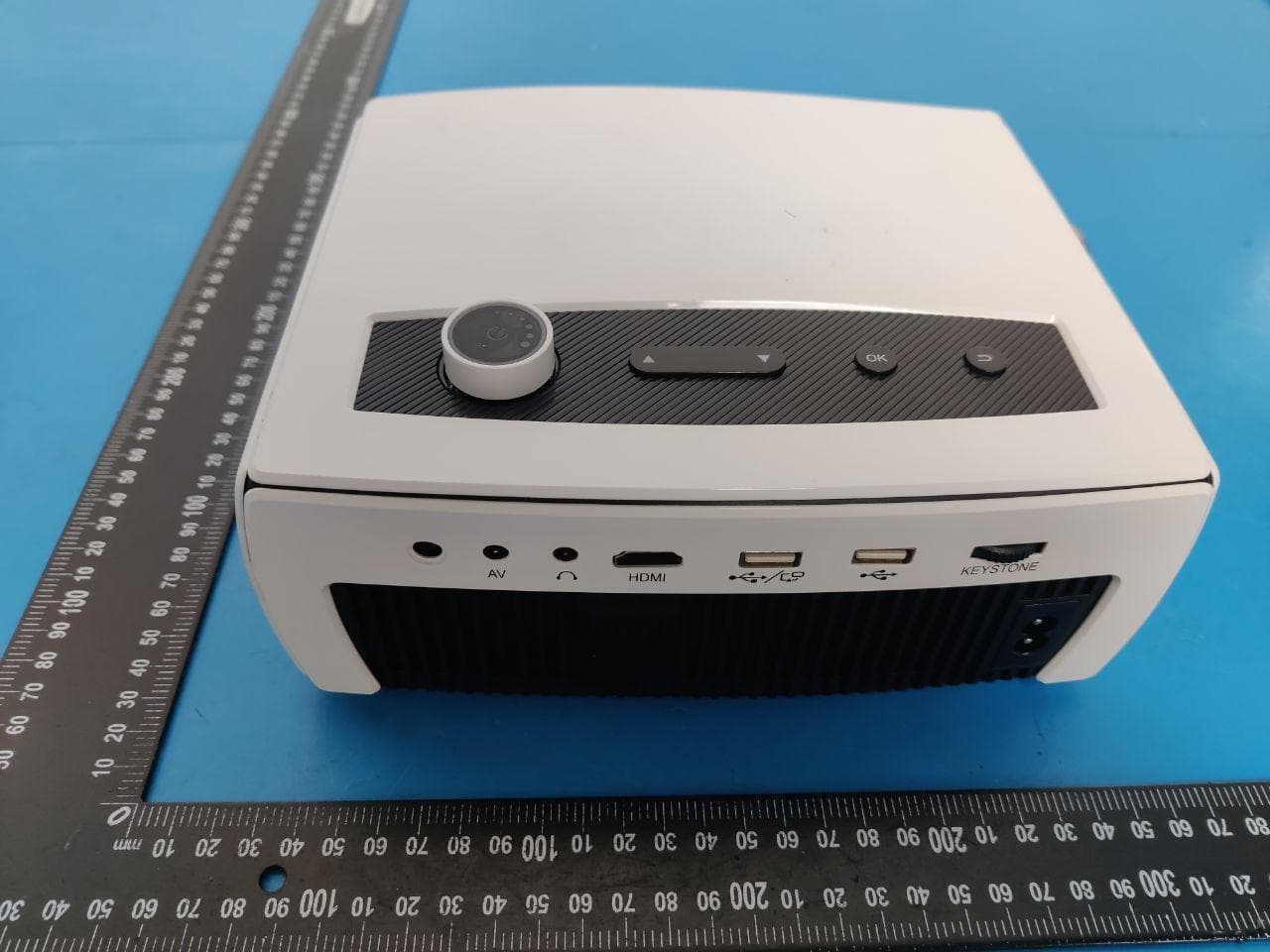
Click to zoom
Application Details
- Equipment Class
- DSS - Part 15 Spread Spectrum Transmitter
- Date of Grant
- Apr 23, 2021
- Application Purpose
- Original Equipment
- Date of Application
- Apr 23, 2021
- Equipment Note
- Projector
- Frequency Range
- 2402.00000000 - 2480.00000000
- Country
- China
Documents & Files
Document Text
Text extracted from the exhibit documents filed with the FCC. Open a document above to read the original.
Users Manual
宽:80mm 高:130mm 7 Settings menu 8 Technology Features 5 Connection introduction 5 4.3 5 Miracast settings 4.2. 5 4.2.2 Windows miracast 4.2.3 Wird connect with Apple devices for Screen mirroring 4.2.4 Android Miracast4.2.5 Wireless connect with Apple devices for Screen mirroring 5 4.4. Supported formats:NTSC / PAL 4.5.Audio Device Connection Could connect earphones and other wired speaker devices. 封底 1 2 3 4 1 2 3 4 8.1.Basic parameters 7.1.Picture settings 7.2.System settings 7.3.Other settings 8.2.Projector distance & size NOTE: Because the optical device has about 3% error, the above data is for reference only, please install the projector according to the actual measurement. 1.3 42.5′′ 2.5 86′′ 3 104′′ 4 140′′ 5 176′′ (m) Choose the “Setting” of home page, find the system setting,you can set up the language 7.3.1. Enter to home page,select settings and choose connection settings,then you can connect to WiFi 7.3.2. Enter the page of WiFi network as below picture,select your wireless network from the list and Choose the “Setting” of home page, find the picture setting,you can set up the projection mode, image scaling, aspect ratio,picture settings of the Multi-media Input-source settings Multi-media Input-source settings Picture settings projection modeimage scaling aspect ratipicture settings System settings Language selection Software upgradeRestore factory settings Auto sleep Multi-media Input-source settings Picture settings projection modeimage scaling aspect ratipicture settings System settings Language selection Software upgradeRestore factory settings Auto sleep connections setting up WIFI set up HDMI AV MuItiScreen MuItiScreen HDMI AV Select Wird connect with Apple devices for Screen mirroring 1.Please connect Apple devices with USB interface of projector by Apple data cable(refer to picture ①). NOTE: If the connection is right, Apple devices will popups a ‘Trust This devices’ message, please select “ Trust”(refer to picture ②). 2.Enter a Apple devices password for mirroring. Select Windows miracast 1.Your device MUST be on the same Wi-Fi network as the projector. Or connect the computer device to the wireless network sent by the projector. 2.Find the settings menu on your computer to access your display device or screen mirroring to connect the screen receiving device. Choose the iOS miracast on the home page. NOTE: Apple devices for screen mirroring or projector upgrade software for the first time, the projector needs to be activated through networking. 1.Please make sure the IOS device and the projector are on the same network, Or connect the IOS device to the wireless network sent by the projector. 2.Enter the control center on the IOS device terminal and click Screen Mirroring. 3.Select the name of the corresponding projector. Select Android Miracast 1.Choose the android miracast on the home page. Select the wireless display settings function on android phone. NOTE: Different android phones have different ways of opening multi-screen function. Please refer to the instructions of android phones for details. 2.Select the corresponding projector device name. NOTE:Please make sure the mobile phone and the projector are on the same network(Different projector shows different name, please focus on the actual situation .) Picture of mobile phone connecting to projector ① Mirror your iPhone,iPad or iPod touch Make sure that iOS device is connected to the same network as your projector,or connect iOS device with AP by Projector: NEWAP-300A 1.On your iOS device,open Control Center and tap screen Mirroring. 2.Looking for devices that can be mirrored on. 3.Select NETLINK-300A(icast) from the list. Window Cast MiracastiOS Cast iOS Cable CastSettings DLNA Figure 2: Figure 1: 安卓手机 KEYSTONE KEYSTONE KEYSTONE KEYSTONE Figure 1: Figure 2: Due to continuous improvement, actual product may different from the manual, manual is for reference only. User guide 1 Safety Notice: 1.1 Please read Manual carefully before you use the projector; 1.2 To ensure stable power supply, please use national standard power cable and power cord with grounding; 1.3 Please use the same power voltage as the projector marked; 1.4 Please do not open the projector, otherwise the supplier will not afford warranty service; 1.5 Do not look directly at the projector lens while the machine is working to avoid damage your eyes; 1.6 To avoid clog of the projector vent, please do not cover with cloth, carpet and other materials; 1.7 This projector does not have waterproof function, please keep it away from rain, moisture and other items containing liquid such as vase, cup, etc; 1.8 To prevent power breakdown, please keep the projector away from rain or water or moisture; 1.9 Turn off and cut off the power supply if do not use this project for a long time; 1.10 Use the originally foam or other unit-shock material to protect projector, if you need transport this projector; 1.11 If you find the projector has problems, please contact with the supplier, do not repair by yourself。 1.12 To extend the projector life span and protect your eyesight, we suggest you may have a break after 3-4 hours using。 Maintain Indication:1-year warranty from factory, for more warranty information, please contact with supplier (warranty service is not including the frame, manual, package, and some subjective idea about the video, sound, image aspects). Interfaces introduction Power input Keystone Earphone slot AV input slot HDMI input slot USB input slot Manual focus KEYSTONE Lens Power button VOL+ VOL-/Left Right Down Up Return OK 2 3 Remote Control Introduction Power Mute Menu Pause Left Right Return Signal Source Vol+ Vol- UP Down 4 Multi-media connection 4.1. USB interface connection Insert the USB into the accordingly slot. (refer to picture below), Choose multi-media signal source, Choose the content which you need display: Movie, Music, Photo, Text.。 Multi-media Input-source Settings MoviePhoto MusiText KEYSTONE HDMI Devices Connection AV Video …
Text truncated - open the document above for the full version.
Cover Letter(s)
4/15/2021 Equipment Autorisation Division Federal Communications Commission 7435 Oakland Mills Road Columbia, MD 21046 FCC ID: 2AZFE-AAOFTO Product Name: Projector Request for Confidentiality Pursuant to Sections 0.457 and 0.459 of the commissions rules, we hereby request that the following documents be held confidential: Schematics Long-term confidential Block diagram Long-term confidential Operation description Long-term confidential These materials contain trade secrets and proprietary information and are not customarily released to the public. The public disclosure of this information might be harmful to the company and provide unjustified benefits to our competitors. Signature: Name Peng.shen Position Quality Manager Company Name Shenzhen Shadow Crown Technology Co., Ltd. Address A9 East 5th Floor, Industrial Building, Longwang Miao, Fuyong District , Shenzhen, Guangdong, China. Tel -86+0755-23319829 Fax / Email [email protected]
Cover Letter(s)
Differences Description We Shenzhen Shadow Crown Technology Co., Ltd. (Singapore) state: Product name: Projector Model: YG431, YG221, YG231, YG251, YG261, YG271, YG331, YG351, YG361, YG381, YG461, YG471, YG521, YG620, YG651, YG661, YG671, YG681 The difference between the models is that the board and key components of each product are the same. Only the model No. will be a little different. 2021-04-16 Name Peng.shen Position Quality Manager Company Name Shenzhen Shadow Crown Technology Co., Ltd. Address A9 East 5th Floor, Industrial Building, Longwang Miao, Fuyong District, Shenzhen, Guangdong, P.R. China. Tel -86+0755-23319829 Fax / Email [email protected] (Signature)
External Photos
FCC ID: 2AZFE-AAOFTO FCC ID: 2AZFE-AAOFTO FCC ID: 2AZFE-AAOFTO FCC ID: 2AZFE-AAOFTO
ID Label/Location Info
4.5cm 2.5cm FCC ID: 2AZFE-AAOFTO Shenzhen Shadow Crown Technology Co.,Ltd. Product name: Projector Model No.: YG431 This device complies with Part 15 of the FCC Rules. Operation is subject to the following two conditions: (1) this device may not cause harmful interference, and (2) this device must accept any interference received, including interference that may cause undesired operation. Label Location
Internal Photos
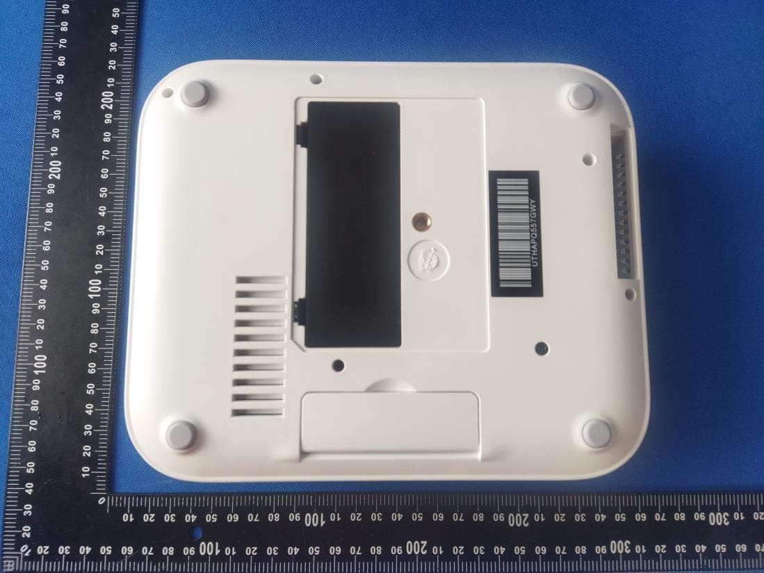
FCC ID: 2AZFE-AAOFTO FCC ID: 2AZFE-AAOFTO FCC ID: 2AZFE-AAOFTO FCC ID: 2AZFE-AAOFTO FCC ID: 2AZFE-AAOFTO FCC ID: 2AZFE-AAOFTO FCC ID: 2AZFE-AAOFTO FCC ID: 2AZFE-AAOFTO FCC ID: 2AZFE-AAOFTO FCC ID: 2AZFE-AAOFTO FCC ID: 2AZFE-AAOFTO FCC ID: 2AZFE-AAOFTO
RF Exposure Info
FCC ID: 2AZFE-AAOFTO RF Exposure evaluation According to 447498 D01 General RF Exposure Guidance v06 The 1-g and 10-g SAR test exclusion thresholds for 100 MHz to 6 GHz at test separation distances ≤ 50 mm are determined by: [(max. power of channel, including tune-up tolerance, mW)/(min. tes t separation distance, mm)] ·[√f(GHz)] ≤ 3.0 for 1-g SAR and ≤ 7.5 for 10-g extremity SAR, where f(GHz) is the RF channel transmit frequency in GHz Power and distance are rounded to the nearest mW and mm before calculation The result is rounded to one decimal place for comparison Worse case is as below: Bluetooth: [2441MHz: 2.343dBm(1.72 mW) output power] ·(1.72mW/5mm) ·[√2.441 (GHz)]= 0.54 <3.0 for 1-g SAR 2.4G WIFI: [2462MHz: 9.476dBm(8.86 mW) output power] ·(8.86mW/5mm) ·[√2.462 (GHz)]= 2.78 <3.0 for 1-g SAR 5G WIFI: [5210MHz: 6.694dBm(4.67 mW) output power] ·(4.67 mW/5mm) ·[√5.21 (GHz)]= 2.13 <3.0 for 1-g SAR BT and wifi don't transmit at the same time. Then SAR evaluation is not required
Test Report
FCC TEST REPORT FCC ID: 2AZFE-AAOFTO On Behalf of Shenzhen Shadow Crown Technology Co., Ltd. Projector Model No.: YG431, YG221, YG231, YG251, YG261, YG271, YG331, YG351, YG361, YG381, YG461, YG471, YG521, YG620, YG651, YG661, YG671, YG681 Prepared for : Shenzhen Shadow Crown Technology Co., Ltd. Address : A9 East 5th Floor, Industrial Building, Longwang Miao, Fuyong District , Shenzhen, Guangdong, China. Prepared By : Shenzhen Alpha Product Testing Co., Ltd. Address : Building i, No.2, Lixin Road, Fuyong Street, Bao’an District, 518103, Shenzhen, Guangdong, China Report Number : A2103194-C01-R01 Date of Receipt : March 24, 2021 Date of Test : March 24, 2021-March 30, 2021 Date of Report : April 19, 2021 Version Number : V0 Page 2 of 69 Report No.: A2103194-C01-R01 TABLE OF CONTENTS Description Page 1. Summary Of Standards And Results ................................................................................................... 6 1.1. Description of Standards and Results .......................................................................... 6 2. General Information .............................................................................................................................. 7 2.1. Description of Device (EUT) ....................................................................................... 7 2.2. Accessories of Device (EUT) ...................................................................................... 8 2.3. Tested Supporting System Details ............................................................................... 8 2.4. Block Diagram of connection between EUT and simulators ...................................... 8 2.5. Test Mode Description ................................................................................................. 8 2.6. Test Conditions ............................................................................................................ 8 2.7. Test Facility ................................................................................................................. 9 2.8. Measurement Uncertainty ............................................................................................ 9 2.9. Test Equipment List ................................................................................................... 10 3. Maximum Peak Output Power ........................................................................................................... 11 3.1. Limit .......................................................................................................................... 11 3.2. Test Procedure ........................................................................................................... 11 3.3. Test Setup ................................................................................................................... 11 3.4. Test Result ................................................................................................................. 11 4. Bandwidth ............................................................................................................................................. 12 4.1. Limit .......................................................................................................................... 12 4.2. Test Procedure ........................................................................................................... 12 4.3. Test Result ................................................................................................................. 12 5. Carrier Frequency Separation ............................................................................................................ 22 5.1. Limit .......................................................................................................................... 22 5.2. Test Procedure ........................................................................................................... 22 5.3. Test Result ................................................................................................................. 22 6. Number Of Hopping Channel ............................................................................................................. 24 6.1. Limit .......................................................................................................................... 24 6.2. Test Procedure ........................................................................................................... 24 6.3. Test Result ................................................................................................................. 24 7. Dwell Time ............................................................................................................................................ 26 7.1. Test limit .................................................................................................................... 26 7.2. Test Procedure ........................................................................................................... 26 7.3. Test Result ................................................................................................................. 26 8. Radiated Emissions .............................................................................................................................. 32 8.1. Limit .......................................................................................................................... 32 8.2. Block Diagram of Test setup ..................................................................................... 33 8.3. Test Procedure ........................................................................................................... 34 8.4. Test Result ................................................................................................................. 34 9. Band Edge Compliance ...................................................................................…
Text truncated - open the document above for the full version.
Test Report
Page 41 of 69 Report No.: A2103194-C01-R01 Hopping-on Test Mode: π/4-DQPSK-Low 20 30 40 50 60 70 80 90 10 0 110 2380 2390 2400 2410 2420 2430 2440 2450 Level in dB 礦 /m FCC P A RT 15 2G Hz _P K FCC P A RT 15 2G Hz _A VG 2.3900240 00 G Hz 39.777 d B礦/m 2.3900030 00 G Hz 30.079 d B礦/m Test Mode: π/4-DQPSK-High 20 30 40 50 60 70 80 90 10 0 110 2450 2460 2470 2480 2490 2500 Level in dB 礦 /m FCC P ar t 15 2G Hz_P K FCC P ar t 15 2G Hz_A VG 2.4835250 00 G Hz 42.798 d B礦/m 2.4835400 00 G Hz 31.648 d B礦/m hopping-on Page 42 of 69 Report No.: A2103194-C01-R01 Hopping-off Test Mode: 8-DPSK-Low 20 25 30 35 40 45 50 55 60 65 70 75 80 85 90 95 10 0 2380 2390 2400 2410 2420 2430 2440 2450 Level in dB 礦 /m FCC P A RT 15 2G Hz _P K FCC P A RT 15 2G Hz _A VG 2.3899400 00 G Hz 40.597 d B礦/m 2.3899540 00 G Hz 30.238 d B礦/m Test Mode: 8-DPSK-High 20 30 40 50 60 70 80 90 10 0 110 2450 2460 2470 2480 2490 2500 Level in dB 礦 /m FCC P ar t 15 2G Hz_P K FCC P ar t 15 2G Hz_A VG 2.4835900 00 G Hz 45.531 d B礦/m 2.4835400 00 G Hz 35.874 d B礦/m Page 43 of 69 Report No.: A2103194-C01-R01 Hopping-on Test Mode: 8-DPSK -Low 20 30 40 50 60 70 80 90 10 0 110 2380 2390 2400 2410 2420 2430 2440 2450 Level in dB 礦 /m FCC P A RT 15 2G Hz _P K FCC P A RT 15 2G Hz _A VG 2.3900030 00 G Hz 41.564 d B礦/m 2.3900030 00 G Hz 30.227 d B礦/m Test Mode: 8-DPSK –Hjigh 20 30 40 50 60 70 80 90 10 0 110 2450 2460 2470 2480 2490 2500 Level in dB 礦 /m FCC P ar t 15 2G Hz_P K FCC P ar t 15 2G Hz_A VG 2.4835250 00 G Hz 42.068 d B礦/m 2.4835400 00 G Hz 30.999 d B礦/m hopping-on Page 44 of 69 Report No.: A2103194-C01-R01 Conducted Method Band Edge NVNT 1-DH1 2402MHz Ant1 Hopping Emission Band Edge NVNT 1-DH1 2402MHz Ant1 No-Hopping Emission Page 45 of 69 Report No.: A2103194-C01-R01 Band Edge NVNT 1-DH1 2480MHz Ant1 Hopping Emission Band Edge NVNT 1-DH1 2480MHz Ant1 No-Hopping Emission Page 46 of 69 Report No.: A2103194-C01-R01 Band Edge NVNT 2-DH1 2402MHz Ant1 Hopping Emission Band Edge NVNT 2-DH1 2402MHz Ant1 No-Hopping Emission Page 47 of 69 Report No.: A2103194-C01-R01 Band Edge NVNT 2-DH1 2480MHz Ant1 Hopping Emission Band Edge NVNT 2-DH1 2480MHz Ant1 No-Hopping Emission Page 48 of 69 Report No.: A2103194-C01-R01 Band Edge NVNT 3-DH1 2402MHz Ant1 Hopping Emission Band Edge NVNT 3-DH1 2402MHz Ant1 No-Hopping Emission Page 49 of 69 Report No.: A2103194-C01-R01 Band Edge NVNT 3-DH1 2480MHz Ant1 Hopping Emission Band Edge NVNT 3-DH1 2480MHz Ant1 No-Hopping Emission Page 50 of 69 Report No.: A2103194-C01-R01 10. Power Line Conducted Emissions 10.1.Block Diagram of Test Setup 10.2.Limit Frequency Maximum RF Line Voltage Quasi-Peak Level dB(V) Average Level dB(V) 150kHz ~ 500kHz 66 ~ 56* 56 ~ 46* 500kHz ~ 5MHz 56 46 5MHz ~ 30MHz 60 50 Notes: 1. * Decreasing linearly with logarithm of frequency. 2. The lower limit shall apply at the transition frequencies. 10.3.Test Procedure (1) The EUT was placed on a non-metallic table, 80cm above the ground plane. (2) Setup the EUT and simulator as shown in 10.1 (3) The EUT Power connected to the power mains through a power adapter and a line impedance stabilization network (L.I.S.N1). The other peripheral devices power cord connected to the power mains through a line impedance stabilization network (L.I.S.N2), this provided a 50-ohm coupling impedance for the EUT (Please refer to the block diagram of the test setup and photographs). Both sides of power line were checked for maximum conducted interference. In order to find the maximum emission, the relative positions of equipments and all of the interface cables were changed according to ANSI C63.10 :2013on conducted Emission test. (4) The bandwidth of test receiver is set at 10KHz. (5) The frequency range from 150 KHz to 30MHz is checked. 10.4.Test Result PASS. (See below detailed test data) Note: If peak Result comply with AV limit, QP and AV Result is deemed to comply with AV limit EUT LISN LISN PC System 80cm Receiver :50 Terminator 0.8m Page 51 of 69 Report No.: A2103194-C01-R01 Pol Line Pol Neutral Remark: All modes have been tested, and only worst data of GFSK was listed in this report. Page 52 of 69 Report No.: A2103194-C01-R01 11. Antenna Requirements 11.1.Limit For intentional device, according to FCC 47 CFR Section 15.203, an intentional radiator shall be designed to ensure that no antenna other than that furnished by the responsible party shall be used with the device. And according to FCC 47 CFR Section 15.247 (b), if transmitting antennas of directional gain greater than 6dBi are used, the power shall be reduced by the amount in dB that the directional gain of the antenna exceeds 6dBi. 11.2.Result The EUT antenna is Internal antenna. It complies with the standard requirement. Page 53 of 69 Report No.: A2103194-C01-R01 12. Test Setup Photo 12.1.Photos of Radiated emission Page 54 of 69 Report No.: A2103194-C01-R01 12.2.Photos of Power Line Conducted Emission Test Page 55 of 69 Report No.: A2103194-C01-R01 13. Photos Of EUT Page 56 of 69 Report No.: A2103194-C01-R01 Page 57 of 69 Report No.: A2103194-C01-R01 Page 58 of 69 Report No.: A2103194-C01-R01 Page 59 of 69 Report No.: A2103194-C01-R01 Page 60 of 69 Report No.: A2103194-C01-R01 Page 61 of 69 Report No.: A2103194-C01-R01 Page 62 of 69 Report No.: A2103194-C01-R01 Page 63 of 69 Report No.: A2103194-C01-R01 Page 64 of 69 Report No.: A2103194-C01-R01 Page 65 of 69 Report No.: A2103194-C01-R01 Page 66 of 69 Report No.: A2103194-C01-R01 Page 67 of 69 Report No.: A2103194-C01-R01 Page 68 of 69 Report No.: A2103194-C01-R01 Page 69 of 69 Report No.: A2103194-C01-R01 ---------THE END OF REPORT-------
Test Setup Photos
FCC ID: 2AZFE-AAOFTO 1.1. Photos of Radiated emission FCC ID: 2AZFE-AAOFTO 1.2. Photos of Power Line Conducted Emission Test FCC ID: 2AZFE-AAOFTO Wifi
Contact Information
Applicant
peng shen(Quality Manager)
Test Firm
Shenzhen Alpha Product Testing Co., LTD.Simple Guan
[email protected]+86 755 29766001-810
Technical Specifications
| # | Rule Parts | Frequency Range | Power Output |
|---|---|---|---|
| 1 | 15C | 2.40 GHz - 2.48 GHz | 1.71 mW |
Other Applications from Shenzhen Shadow Crown Technology Co.,Ltd.
2AZFE-ONO3PRO
Jun 27, 2024LED Projector
Equipment Class
DSS - Part 15 Spread Spectrum Transmitter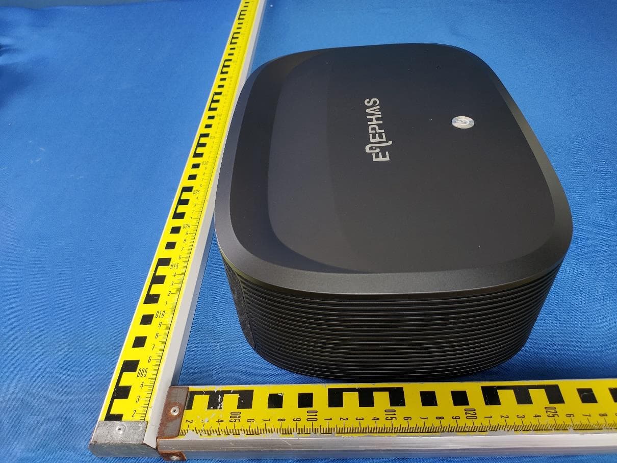
2AZFE-AAO-YG
Sep 05, 2023LED Projector
Equipment Class
NII - Unlicensed National Information Infrastructure TX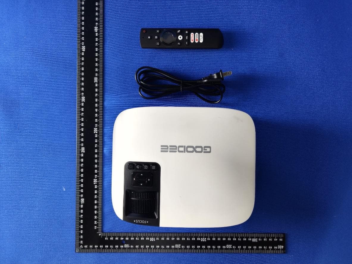
2AZFE-AAO-MOVIN
Jul 20, 2023LED Projector
Equipment Class
DSS - Part 15 Spread Spectrum Transmitter