Text extracted from the exhibit documents filed with the FCC. Open a document above to read the original.
1.Identification of each part 2.Check the connection port and wiring 3. Front display 4. Product Introduction 5. Product overview 6. Installation and operation 7. Register indicators 8. How to use 9. Terminal definition 10. Power and external connections 11. Product specification 12. Block diagram User manual 1. Identification of each part 2. Check the connection port and wiring ③DC power supply connection port: +12 [V DC ] ④USB device connection port: 5pin, firmware download, debug ⑤USB host connection port: 4pin, application download, debug ⑥Ethernet connection Port: 8pin, 10/100 ⑦USB device connection port: 5pin, debug message ①Power indicateLED ②Factory reset ③DC power supply input ④USB OTG (for debug) ⑤USB host (for debug) ⑥Ethernet ⑦USB device (for debug) 1234567 1234567 3. Front display 4. Product Introduction •MPI 3.0 gateway was developed based on proprietary protocol networking for IoT technology and is a facility that wirelessly transmits work instruction information received from Ex-DPS/DAS Manager to Indicator. •Dimension: 150 X 80 X 50 mm (Length x Width x Depth) •The case is matte black, the logo and product number are white •The button has a Factory Reset function. •Connect power and connect to the server using an Ethernet cable. . •Wireless •Frequency •Data Rate •Distance •Interface Sub-GHz 900MHz ISM Band ~250Kbps ~10m Power, Ethernet Specification . Installation and operation •Check the space where you want to install the gateway in the workshop and install the gateway. •Connect a pre-prepared LAN line to the Ethernet port. •Apply power to the Indicator group that should work together. •Verify that each ID is displayed in the Indicator. •Connect power DC 12V to the gateway. Verify that the green LED is incoming. •Check that the IDs of the indicators disappear and that only the LEDs on both sides of the indicator are illuminated. •The server with the barcode scanner recognizes the gateway. •Verify that each indicator is connected through the gateway on the server. . Register Indicators Each cell is assigned a unique QR code, and when it is scanned by the scanner, the unique QR code of the indicator to be newly registered is rescanned and automatically registered to the server. ▪Indicator registration using QR code ▪Equipped with separate LED lights Attach it to each cell to use LED lights that work with the indicator to increase visibility of the operator to prevent job errors. -Connect the optional LED bar for 5V to the 4pin connector. . . How to use 1) Product code recognition by item Scan the bar code of the product you want to input. 2) Distribution of required quantity for each destination It will identify the final quantity required to be shipped by dealers and display the goods code and quantity required in each indicator through the Gateway. At this point, the LED on the confirmation button indicates that it must be received. 3) Check after loading goods Insert the quantity marked on the indicator for each delivery box and press the confirm button. When the confirm button is pressed, the status of the indicator changes to LED ON -> LED OFF. When all confirm buttons are pressed, the next item is scanned. Green LED's mean that items must be loaded in green box, red LED'sin red box, yellow LED'sin yellow box, and blue LED'sin blue box. 4) When all goods have been loaded, the invoice is printed. 10. Power and External Connections . Connector Definition1. DC jack 2. Mini USB 3. USB Host 3. Ethernet Port PinNameDescription 1VBUS+5V 2D-Data - 3D+Data + 4IDOTG Selection 5GNDGround PinNameDescription 1VBUS+5V 2D-Data - 3D+Data + 4GNDGround PinNameDescription 1V++5V(center pin) 2GNDGround PinNameDescription 1TX+Transmit Data+ 2TX-Transmit Data- 3RX+Receive Data+ 4NCNot Connected 5NCNot Connected 6RX-Receive Data- 7NCNot Connected 8NCNot Connected 9LED1LED1 Cathode 10GNDLED1 Anode 11LED2LED2 Cathode 12GNDLED2 Anode •The MPI 3.0 Gateway has the following ranges of supply power and voltage ranges. ✓Input voltage range: +8 ~ 12 [V DC ] ✓Maximum power consumption: < 15W This device complies with Part 15 of the FCC Rules. Operation is subject to the following two conditions: 1. This device may not cause harmful interference. 2. This device must accept any interference received, including interference that may cause undesired operation. Note: This equipment has been tested and found to comply with the limits for a Class A digital device, pursuant to Part 15 of the FCC Rules. These limits are designed to provide reasonable protection against harmful interference when the equipment is operated in a commercial environment. This equipment generates, uses, and can radiate radio frequency energy, and if it is not installed and used in accordance with the instruction manual, it may cause harmful interference to radio communications. Operation of this equipment in a residential area is likely to cause harmful interference, in which case the user will be required to correct the interference at his own expense. Modifications: Any modifications made to this device that are not approved by CJ Logistics Corporationmay void the authority granted to the user by the FCC to operate this equipment. Indicator & Gateway has been usedto facilitate the delivery of various instructions for the work performed in the logistics distribution to the field workers. ThisdeviceisClass Athan Class B since it is using for Industrial not for household.
Rev 11/20/07 Federal Communications Commission Authorization and Evaluation Division Confidentiality Request regarding application for certification of FCC ID:(2AZJM-MPS3GW01). Pursuant to Sections 0.457 and 0.459 of the Commission’s Rules, we hereby request confidential treatment of information accompanying this application as outlined below: Exhibit Type Block Diagram, Circuit Diagram, Layout, Antenna, operational description File Name “MPS3.0-Gateway_block diagram” “CircuitDiagram-MPS_GW_(VER3.0B)” “Layout_bottom,RF-module,top” Antenna “861784680746480915at43a0026” OperationalDescription-MPS3.0-Gateway- 210513 The above materials contain trade secrets and proprietary information not customarily released to the public. The public disclosure of these materials may be harmful to the applicant and provide unjustified benefits to its competitors. The applicant understands that pursuant to Section 0.457 of the Rules, disclosure of this application and all accompanying documentation will not be made before the date of the Grant for this application. Pursuant to DA04-1705 June 15, 2004 of the Commission’s public notice, we also request temporary confidential treatment of information accompanying this application as outlined below for (PLEASE ENTER HOW MANY DAYS 45, 90, 180): 180 days Exhibit Type File Name Manual, internal photos “Gateway-UserManual_FCC_organized” 03. Internal Photos_MPS3.0-GW01 Rev 11/20/07 Sincerely, (signature) (printed name) Jinman, Na
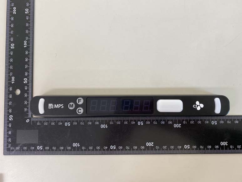
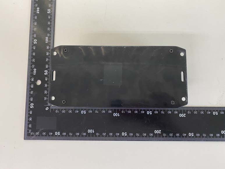
Page: 1 / 4 Copyright ⓒ 2021, Lab-T, Inc. External Photos Page: 2 / 4 Copyright ⓒ 2021, Lab-T, Inc. External Photos Front Rear Page: 3 / 4 Copyright ⓒ 2021, Lab-T, Inc. External Photos Top Bottom Page: 4 / 4 Copyright ⓒ 2021, Lab-T, Inc. External Photos Left Right
Page: 1 / 3 Copyright ⓒ 2021. Lab-T, Inc. Internal Photos Page: 2 / 3 Copyright ⓒ 2021. Lab-T, Inc. Internal Photos Main Board_Front Main Board_Rear Page: 3 / 3 Copyright ⓒ 2021. Lab-T, Inc. Internal Photos RF Module_Front RF Module _Rear . Antenna
FCC ID : 2AZJM-MPS3GW01 1. Regulation 2. RF Exposure Compliance Issue According to §15.247(i), systems operating under the provisions of this section shall be operated in a manner that ensures that the public is not exposed to radio frequency energy levels in excess of the Commission's guidelines. See § 1.1307(b)(1) of this Chapter. RF EXPOSURE Limits for Maximum Permissive Exposure: RF exposure is calculated. Limits for General Population / Uncontrolled Exposure 0.3 ~ 1.346141.63*(100)30 Frequency Range Electric Field Strength [V/m] Magnetic Field Strength [A/m] Power Density [mW/cm 2 ] Averaging Time [minute] 30 30 ~ 30027.50.0730.230 300 ~ 1 500//f/1 500 30 1.34 ~ 30824/f2.19/f*(180/f2) 1 500 ~ 15 000//130 f=frequency in MHz, *= plane-wave equivalent power density MPE (Maximum Permissive Exposure) Prediction Predication of MPE limit at a given distance: Equation from KDB 447498 D01 General RF Exposure Guidance v06 S = power density [mW/cm 2 ] P = Power input to antenna [mW] G = Power gain of the antenna in the direction of interest relative to an isotropic radiator R = distance to the center of radiation of the antenna [cm] The information should be included in the user’s manual: This appliance and its antenna must not be co-located or operation in conjunction with any other antenna or transmitter. SPGRRPGS4 4 2 Copyright ⓒ 2021. Lab-T, Inc. Page :1 / 5 FCC ID : 2AZJM-MPS3GW01 ( MPE Calculations : Module 1_GFSK - Frequency Range : 903 MHz ~ 927 MHz - Measured RF Maximum Output Power(Avg.) : -11.60 dBm - Target Power & Tolerance -12.60 dBm & ± 1.00 dB ( Maximum : -11.60 dBm & Minimum : -13.60 dBm ) - Maximum Peak Antenna Gain : -1.00 dBi - Maximum Output Power for the Calculation :-11.60 dBm The EUT will only be used with a separation of 5 millimeters or lesser between the antenna and the body of the The MPE calculation for this exposure is shown below. - EIRP = P + G- NOTE = -11.60 dBm + -1.00dBiP : Max tuneup Power (dBm) = -12.60 dBmG : Maximum Peak Antenna Gain (dBi) =0.05 mW Power Density at the specific separation - S = EIRP / (4 X R 2 π) - NOTE =0.05/ ( 4 X 0.5^2 X π ) S : Maximum Power Density (mW/cm 2 ) = 0.017 492 mW/cm 2 EIRP : Equivalent Isotropic Radiated Power (mW) R : Distance to the center of the radiation of the antenna0.5 cm ) Limit :0.62 mW/cm 2 (927 MHz) Copyright ⓒ 2021. Lab-T, Inc. Page :2 / 5 FCC ID : 2AZJM-MPS3GW01 ( MPE Calculations : Module 2_GFSK - Frequency Range : 903 MHz ~ 927 MHz - Measured RF Maximum Output Power(Avg.) : -11.76 dBm - Target Power & Tolerance -12.75 dBm & ± 1.00 dB ( Maximum : -11.75 dBm & Minimum : -13.75 dBm ) - Maximum Peak Antenna Gain : -1.00 dBi - Maximum Output Power for the Calculation :-11.75 dBm The EUT will only be used with a separation of 5 millimeters or lesser between the antenna and the body of the The MPE calculation for this exposure is shown below. - EIRP = P + G- NOTE = -11.75 dBm + -1.00dBiP : Max tuneup Power (dBm) = -12.75 dBmG : Maximum Peak Antenna Gain (dBi) =0.05 mW Power Density at the specific separation - S = EIRP / (4 X R 2 π) - NOTE =0.05/ ( 4 X 0.5^2 X π ) S : Maximum Power Density (mW/cm 2 ) = 0.016 899 mW/cm 2 EIRP : Equivalent Isotropic Radiated Power (mW) R : Distance to the center of the radiation of the antenna0.5 cm ) Limit :0.62 mW/cm 2 (927 MHz) Copyright ⓒ 2021. Lab-T, Inc. Page :3 / 5 FCC ID : 2AZJM-MPS3GW01 ( MPE Calculations : Module 3_GFSK - Frequency Range : 903 MHz ~ 927 MHz - Measured RF Maximum Output Power(Avg.) : -11.90 dBm - Target Power & Tolerance -12.80 dBm & ± 1.00 dB ( Maximum : -11.80 dBm & Minimum : -13.80 dBm ) - Maximum Peak Antenna Gain : -1.00 dBi - Maximum Output Power for the Calculation :-11.80 dBm The EUT will only be used with a separation of 5 millimeters or lesser between the antenna and the body of the The MPE calculation for this exposure is shown below. - EIRP = P + G- NOTE = -11.80 dBm + -1.00dBiP : Max tuneup Power (dBm) = -12.80 dBmG : Maximum Peak Antenna Gain (dBi) =0.05 mW Power Density at the specific separation - S = EIRP / (4 X R 2 π) - NOTE =0.05/ ( 4 X 0.5^2 X π ) S : Maximum Power Density (mW/cm 2 ) = 0.016 705 mW/cm 2 EIRP : Equivalent Isotropic Radiated Power (mW) R : Distance to the center of the radiation of the antenna0.5 cm ) Limit :0.62 mW/cm 2 (927 MHz) Copyright ⓒ 2021. Lab-T, Inc. Page :4 / 5 FCC ID : 2AZJM-MPS3GW01 ( Note1: Each transmitter signal has nothing to do with each other. 100 = 5.10961 % Distance to the center of the radiation of the antenna0.5 cm ) Limit : ≤ 100 % /1)+ ( 0.01671 / 1 )] * (Module 2 Result(mW/cm 2 ) / Limit(mW/cm 2 )) (Module 3 Result(mW/cm 2 ) / Limit(mW/cm 2 ))] =+ * 100 ] [( 0.01749 / 1 ) ( 0.01690 [ (Module 1 Result(mW/cm 2 ) / Limit(mW/cm 2 ) MPE Calculations : Max simultaneous transmission MPE mW/cm 2 - NOTE Module 1 + Module 2 + Module 3 Max simultaneous transmission MPE Module 2 = 0.05 mW Module 1 = 0.05 mW Total Module 1 + Module 2 + Module 3 - NOTE Module 1 + Module 2 + Module 3 -Total EIRP = ( 0.05 + 0.05 + 0.05 ) mW = 0.15 mW Module 3 = 0.05 mW -Total S = Module 1 = Module 2 = Module 3 = 0.01749 0.01690 mW/cm 2 0.01671 mW/cm 2 Copyright ⓒ 2021. Lab-T, Inc. Page :5 / 5
REPORT No.:TRRFCC21-0004(1) Total 55 pages TRF-R-003(00) Page: 2 / 55 Copyright ⓒ 2021, Lab-T, Inc. CONTENTS 1. Revision history ............................................................................................................................................... 3 2. Information ...................................................................................................................................................... 4 2.1 Applicant Information ............................................................................................................................................................ 4 2.2 Test Laboratory information .................................................................................................................................................. 4 2.3 Test Location .............................................................................................................................................................................. 4 3. Information About Test Equipment .............................................................................................................. 5 3.1 Equipment Information ............................................................................................................................................................ 5 3.2 Antenna Information ................................................................................................................................................................. 5 3.3 Test Frequency .......................................................................................................................................................................... 5 3.4 Tested Companion Device Information ............................................................................................................................. 5 3.5 Equipment Channel List ......................................................................................................................................................... 6 4. Test Report ....................................................................................................................................................... 7 4.1 Summary ...................................................................................................................................................................................... 7 4.2 Measurement Uncertainty .................................................................................................................................................... 7 4.3 Transmitter Requirements ..................................................................................................................................................... 8 4.3.1 Antenna Requirement .................................................................................................................................................... 8 4.3.2 Maximum Peak Output Power .................................................................................................................................... 9 4.3.3 Peak Power Spectral Density ............................................................................................ ......................................... 14 4.3.4 6 dB Bandwidth(DTS Bandwidth) ............................................................................................................................. 21 4.3.5 Spurious Emission, Band Edge, and Restricted bands .................................................................................... 28 4.3.6 Conducted Emission ..................................................................................................................................................... 52 APPENDIX I ............................................................................................................................................................ 54 REPORT No.:TRRFCC21-0004(1) Total 55 pages TRF-R-003(00) Page: 3 / 55 Copyright ⓒ 2021, Lab-T, Inc. 1. Revision history Test Report No. Date Description TRRFCC21-0004 21.04.15 Initial issue TRRFCC21-0004(1) 21.05.18 Follow the guidance of the KDB 662911 D01 Multiple Transmitter Output v02r01 to revise this test report REPORT No.:TRRFCC21-0004(1) Total 55 pages TRF-R-003(00) Page: 4 / 55 Copyright ⓒ 2021, Lab-T, Inc. 2. Information 2.1 Applicant Information Applicant name CJ Logistics Corporation Address 53, Sejong-daero 9-gil, Jung-gu, Seoul, Republic of Korea Telephone No. +82 2-700-0418 Person in charge Jinman Na / Senior Engineer Manufacturer DoThing Co.,LTD. Address 510, 67, Saebitgongwon-ro, Gwangmyeong-si, Gyeonggi-do, Republic of Korea 2.2 Test Laboratory information Corporate name Lab-T, Inc. Representative Jong-Young Kim Address 2182-42 Baegok-daero, Mohyeon-eup, Cheoin-gu, Yongin-si, Gyeonggi-do 17036, Korea Telephone +82-31-322-6767 Fax +82-31-322-6768 E-mail [email protected] FCC Designation No. KR0159 FCC Registration No. 133186 2.3 Test Location Test building used Address Building T 2182-42 Baegok-daero, Mohyeon-eup, Cheoin-gu, Yongin-si, Gyeonggi-do 17036, Korea Building L 2182-40 Baegok-daero, Mohyeon-eup, Cheoin-gu, Yongin-si, Gyeonggi-do 17036, Korea Building A 2182-44 Baegok-daero, Mohyeon-eup, Cheoin-gu, Yongin-si, Gyeonggi-do 17036, Korea REPORT No.:TRRFCC21-0004(1) Total 55 pages TRF-R-003(00) Page: 5 / 55 Copyright ⓒ 2021, Lab-T, Inc. 3. Information About Test Equipment 3.1 Equipment Information Equipment type MPS3.0 Gateway Model name MPS3.0-GW01 Frequency range 903 MHz ~ 927 MHz Modulation type GFSK Power supply DC 12.0 V H/W version 3.0B S/W version 20200131 Note 1 : The above EUT information was declared by the manufacturer. 3.2 Antenna Information Type Model No. Gain Note. Chip Antenna 0915AT43A0026 -1.0 dBi - Note 1 : The modules all use the same antenna. 3.3 Test Frequency Test mode Test frequency (MHz) Lowest Frequency Middle Frequency Highest Frequency Module 1_GFSK …
Text truncated - open the document above for the full version.
Page: 1 / 4 Copyright ⓒ 2021. Lab-T, Inc. Test Setup Photos Page: 2 / 4 Copyright ⓒ 2021. Lab-T, Inc. Test Setup Photos Radiated Emission_9 kHz ~ 30 MHz Test distance : 3 m, height of table : 0.8 m Radiated Emission_30 MHz ~ 1 GHz Test distance : 3 m, height of table : 0.8 m Page: 3 / 4 Copyright ⓒ 2021. Lab-T, Inc. Test Setup Photos Radiated Emission_1 GHz ~ 10 GHz Test distance : 1 m, height of table : 1.5 m Conducted Emission_FRONT Page: 4 / 4 Copyright ⓒ 2021. Lab-T, Inc. Test Setup Photos Conducted Emission_REAR
| # | Rule Parts | Frequency Range | Power Output |
|---|---|---|---|
| 1 | 15C | 903 MHz - 927 MHz | 90.00 µW |

MPS3.0 MPI (Multi-Purpose Indicator)
Equipment Class
DTS - Digital Transmission System