FCCID.CO- FCC ID Database
HomeCompaniesEquipment ClassesSearch

© 2026 FCC ID Database. All rights reserved.

AboutContactData sourced from FCC public records
  1. Home/
  2. CJ Logistics Corporation/
  3. 2AZJM-MPS3IND1

2AZJM-MPS3IND1MPS3.0 MPI (Multi-Purpose Indicator)

CJ Logistics Corporation
MPS3.0 MPI (Multi-Purpose Indicator) - FCC ID 2AZJM-MPS3IND1 - CJ Logistics Corporation
Click to zoom

Application Details

Equipment Class
DTS - Digital Transmission System
Date of Grant
May 24, 2021
Application Purpose
Original Equipment
Date of Application
May 19, 2021
Equipment Note
MPS3.0 MPI (Multi-Purpose Indicator)
Frequency Range
903.00000000 - 927.00000000
Company
CJ Logistics Corporation
Country
South Korea

Documents & Files

Select a file to view

Users Manual

↗

Cover Letter(s)

↗
↗
↗

External Photos

↗

ID Label/Location Info

↗

Internal Photos

↗

RF Exposure Info

↗

Test Report

↗

Test Setup Photos

↗

Document Text

Text extracted from the exhibit documents filed with the FCC. Open a document above to read the original.

Users Manual

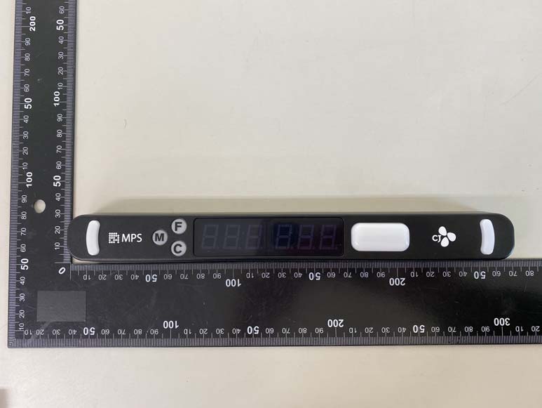
1.Identification of each part 2.Check the connection port and wiring 3.Front display 4.Product Introduction 5.Product Overview 6.Installation and Operation 7.Register Indicators 8.How to use 9.Terminal Definition 10.Power and External Connections 11.Product Specification 12.Block Diagram MP 3.0 IndicatorUser manual 1. Identification of each part 2. Check the connection port and wiring 5.Power cable. connection port (2pin) 6.Lighting LED Connection Port & External Switch (OPTION). Connection port (4pin) 1.Indicator Unique ID 2.Function switch (M / F / C) 3.Display LED & Main Push Button 4.FunctionLED 123 123 4 56 Front display 1.Product number (QR code and text printed) 2.“M” / “F” / “C” button (M: Menu, F: Full, C: Cancel) 3.Blue 3-unit FND display 4.Red 3-unit FND display 5.Four colors (red, blue, green, yellow) LED display & main 6.Company logo 7.Auxiliary white LED 1 3. Front display 2345677 4. Product Introduction •MPI 3.0 Indicator was developed based on proprietary protocol networking for IoT technology and displays work instruction information received from Ex-DPS / DAS Manager. •Dimension: 254 X 30 X 28 [mm] (Length x Width x Depth) •The case is matte black, the logo and product number are white, and the information display LEDs are red and blue. •The operation button indicates that the light is in stock in the direction of the incoming arrow •The Done button is available in four colors (green, orange, red, blue) . 용도 특징 3 Button ✓Menu, Select, Cancel ✓Quantity control, previous / next, etc. 3+3 Digits ✓Location ID, item number quantity, status display ✓Improved utilization and intuitive perception by applying different colors and intervals 1 Button ✓done, confirm ✓Apply 4colors (R / G / B / Y) LED ✓Non-contact structure (inside) for improved durability •Wireless •Frequency •Data Rate •Distance •Interface Sub-GHz 919-923MHzISM Band ~250Kbps ~10m Power, 1 Output(LED), Specification Installation and Operation 6-1. Installation Tip Press the top of the soft guard to open the top turn. Remove Indicator <Mounting condition> <Upon removal> <When installed> -Push the Indicator from the front. -Insert the power cable into the bulkhead of the upper part of the guard. Push to Mount . Register Indicators Each cell is assigned a unique QR code, and when it is scanned by the scanner, the unique QR code of the indicator to be newly registered is rescanned and automatically registered to the server. ▪Indicator registration using QR code ▪Equipped with separate LED lights Attach it to each cell to use LED lights that work with the indicator to increase visibility of the operator to prevent job errors. -Connect the optional LED bar for 5V to the 4pin connector. . . How to use 1) Product code recognition by item Scan the bar code of the product you want to input. 2) Distribution of required quantity for each destination It will identify the final quantity required to be shipped by dealers and display the goods code and quantity required in each indicator through the Gateway. At this point, the LED on the confirmation button indicates that it must be received. 3) Check after loading goods Insert the quantity marked on the indicator for each delivery box and press the confirm button. When the confirm button is pressed, the status of the indicator changes to LED ON -> LED OFF. When all confirm buttons are pressed, the next item is scanned. Green LED's mean that items must be loaded in green box, red LED's in red box, yellow LED's in yellow box, and blue LED's in blue box. 4) When all goods have been loaded, the invoice is printed. 10. Power and External Connections ⚫The MPI 3.0 Indicator has the following ranges of supply power and voltage ranges. -Input voltage range: DC6V ~ DC12V -Maximum power consumption: <15W ⚫The MPI 3.0 Indicator supports the following external interfaces: -Secondary Switch -LED bar for auxiliary lighting (DC 5Vonly) . Connector Definition 12 1: GND 2: VCC (12V) 1. Power Connector 14 1: EXT_LED(5V) 2: GND 3: SW_EXT 4: SW_EXT_Return 2. Auxiliary 4-pin connector 3. F/W Upgrade connector 14 1: VMCU_IN 2: SWCLK 3: SWDIO 4: GND This device complies with Part 15 of the FCC Rules. Operation is subject to the following two conditions: 1. This device may not cause harmful interference. 2. This device must accept any interference received, including interference that may cause undesired operation. Note: This equipment has been tested and found to comply with the limits for a Class A digital device, pursuant to Part 15 of the FCC Rules. These limits are designed to provide reasonable protection against harmful interference when the equipment is operated in a commercial environment. This equipment generates, uses, and can radiate radio frequency energy, and if it is not installed and used in accordance with the instruction manual, it may cause harmful interference to radio communications. Operation of this equipment in a residential area is likely to cause harmful interference, in which case the user will be required to correct the interference at his own expense. Modifications: Any modifications made to this device that are not approved by CJ Logistics Corporationmay void the authority granted to the user by the FCC to operate this equipment. Indicator & Gateway has been used to facilitate the delivery of various instructions for the work performed in the logistics distribution to the field workers. This device is Class A than Class B since it is using for Industrial not for household.

Cover Letter(s)

Rev 11/20/07 Federal Communications Commission Authorization and Evaluation Division Confidentiality Request regarding application for certification of FCC ID:(2AZJM-MPS3IND1). Pursuant to Sections 0.457 and 0.459 of the Commission’s Rules, we hereby request confidential treatment of information accompanying this application as outlined below: Exhibit Type Block Diagram, Circuit Diagram, Layout, Antenna, Operational description File Name “BlockDiagram_MPS3.0-Indicator” “CircuitDiagram_MPI3-IND01” “Layout_bottom,RF-module,top” Antenna “861784680746480915at43a0026” “OperationalDescription-MPS3.0- Indicator-210513-2” The above materials contain trade secrets and proprietary information not customarily released to the public. The public disclosure of these materials may be harmful to the applicant and provide unjustified benefits to its competitors. The applicant understands that pursuant to Section 0.457 of the Rules, disclosure of this application and all accompanying documentation will not be made before the date of the Grant for this application. Pursuant to DA04-1705 June 15, 2004 of the Commission’s public notice, we also request temporary confidential treatment of information accompanying this application as outlined below for (PLEASE ENTER HOW MANY DAYS 45, 90, 180):180days Exhibit Type File Name Manual, Internal Photos “MPS 3.0A Indicator User manual- FCC_organized” 03. Internal Photos_MPS3.0-IND01 Rev 11/20/07 Sincerely, (signature) (printed name) Jinman, Na

External Photos

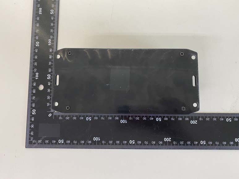
Page: 1 / 4 Copyright ⓒ 2021, Lab-T, Inc. External Photos Page: 2 / 4 Copyright ⓒ 2021, Lab-T, Inc. External Photos Front Rear Page: 3 / 4 Copyright ⓒ 2021, Lab-T, Inc. External Photos Top Bottom Page: 4 / 4 Copyright ⓒ 2021, Lab-T, Inc. External Photos Left Right

Internal Photos

Page: 1 / 3 Copyright ⓒ 2021. Lab-T, Inc. Internal Photos Page: 2 / 3 Copyright ⓒ 2021. Lab-T, Inc. Internal Photos Main Board_Front Main Board_Rear Page: 3 / 3 Copyright ⓒ 2021. Lab-T, Inc. Internal Photos RF Module_Front RF Module_Rear . Antenna

RF Exposure Info

FCC ID : 2AZJM-MPS3IND1 Step.2 For 100 MHz to 6 GHz and test separation distances > 50 mm, the 1-g and 10-g SAR test exclusion thresholds are determined by the following RF EXPOSURE KDB447498 was used as the guidance. SAR test exclusion considerations Step.1 For 100 MHz to 6 GHz and test separation distances ≤ 50 mm, the 1-g and 10-g SAR test exclusion threshold are determined by the following : The test exclusions are applicable only when the minimum test separation distance is ≤ 50 mm, and for transmission frequencies between 100 MHz and 6 GHz. When the minimum test separation distance is < 5 mm, a distance of 5 mm according to 4.1 f) is applied to determine SAR test exclusion. The values 3.0 and 7.5 are referred to as numeric thresholds in step b) below [(max. power of channel, including tune-up tolerance, mW) / (min. test separation distance, mm)] ꞏ [√f(GHz)] ≤ 3.0 for 1-g SAR, and ≤ 7.5 for 10-g extremity SAR where f(GHz) is the RF channel transmit frequency in GHz {[Power allowed at numeric threshold for 50 mm in step a)] + [(test separation distance – 50 mm)ꞏ (f(MHz)/150)]} mW, for 100 MHz to 1500 MHz {[Power allowed at numeric threshold for 50 mm in step a)] + [(test separation distance – 50 mm)ꞏ10]} mW, for > 1500 MHz and ≤ 6 GHz Step.2-1 Step.2-2 Power and distance are rounded to the nearest mW and mm before calculation The result is rounded to one decimal place for comparison Copyright ⓒ 2021. Lab-T, Inc. Page :1 / 4 FCC ID : 2AZJM-MPS3IND1 ( -11.80 dBm Therefore, EUT is not required the SAR Evaluation. ] 0.012 72 Power Density at the specific separation - NOTE- S RF Exposure Compliance Issue f(GHz) : the RF channel transmit frequency in GHz 5.00 )] X R : Distance to the center of the radiation of the antenna5.00 The EUT will only be used with a separation of 5 millimeters or lesser between the antenna and the body of the The MPE calculation for this exposure is shown below. (& Minimum : -13.80 dBm -11.80 dBm Maximum : - NOTE ) P : Max tuneup Power (dBm) - Maximum Output Power for the Calculation : SAR test exclusion considerations : GFSK - Frequency Range : 903 MHz ~ 927 MHz - Measured RF Maximum Output Power (Avg.) : -11.85 dBm 1.00 dB- Target Power & Tolerance -12.80 dBm & ± mm ) =S : Maximum Power Density P(mW) : Max tuneup Power (mW)= [ √( 0.927 )[( 0.07 / = NOTE : f(GHz) was used as worst case is highest frequency. [(P(mW) / R)] X [√f(GHz)] - P = = -11.80 dBm 0.07 mW Copyright ⓒ 2021. Lab-T, Inc. Page :2 / 4 FCC ID : 2AZJM-MPS3IND1 ( - Frequency Range : 2 402 MHz ~ 2 480 MHz SAR test exclusion considerations : π/4DQPSK - Measured RF Maximum Output Power (Avg.) : -1.60 dBm - Target Power & Tolerance -2.00 dBm & ± 0.50 dB Minimum : -2.50 dBm ) - Maximum Output Power for the Calculation :-1.50 dBm ( Maximum : -1.50 dBm & = 0.71 mW P : Max tuneup Power (dBm) Power Density at the specific separation The EUT will only be used with a separation of 50 millimeters or lesser between the antenna and the body of the The MPE calculation for this exposure is shown below. - P = -1.50 dBm- NOTE - S = [(P(mW) / R)] X [√f(GHz)] - NOTE = [( 0.71 / 5.00 )] X [ √( 2.48 ) ]S : Maximum Power Density RF Exposure Compliance Issue Therefore, EUT is not required the SAR Evaluation. highest frequency.antenna5.00mm ) f(GHz) : the RF channel transmit frequency in GHz = 0.222 97P(mW) : Max tuneup Power (mW) R : Distance to the center of the radiation of the NOTE : f(GHz) was used as worst case is Copyright ⓒ 2021. Lab-T, Inc. Page :3 / 4 FCC ID : 2AZJM-MPS3IND1 ( SAR test exclusion considerations : 8DPSK - Frequency Range : 2 402 MHz ~ 2 480 MHz - Measured RF Maximum Output Power (Avg.) : -1.55 dBm - Target Power & Tolerance -2.00 dBm & ± 0.50 dB ( Maximum : -1.50 dBm & Minimum : -2.50 dBm ) - Maximum Output Power for the Calculation :-1.50 dBm The EUT will only be used with a separation of 50 millimeters or lesser between the antenna and the body of the The MPE calculation for this exposure is shown below. - P = -1.50 dBm- NOTE = 0.71 mW P : Max tuneup Power (dBm) Power Density at the specific separation - S = [(P(mW) / R)] X [√f(GHz)] - NOTE f(GHz) : the RF channel transmit frequency in GHz RF Exposure Compliance Issue Therefore, EUT is not required the SAR Evaluation. ]S : Maximum Power Density = 0.222 97P(mW) : Max tuneup Power (mW) R : Distance to the center of the radiation of the NOTE : f(GHz) was used as worst case is highest frequency.antenna5.00mm ) = [( 0.71 / 5.00 )] X [ √( 2.48 ) Copyright ⓒ 2021. Lab-T, Inc. Page :4 / 4

Test Report

REPORT No.:TRRFCC21-0003 Total 36 pages TRF-R-003(00) Page: 2 / 36 Copyright ⓒ 2021, Lab-T, Inc. CONTENTS 1. Revision history ............................................................................................................................................... 3 2. Information ...................................................................................................................................................... 4 2.1 Applicant Information ............................................................................................................................................................ 4 2.2 Test Laboratory information .................................................................................................................................................. 4 2.3 Test Location .............................................................................................................................................................................. 4 3. Information About Test Equipment .............................................................................................................. 5 3.1 Equipment Information ............................................................................................................................................................ 5 3.2 Antenna Information ................................................................................................................................................................. 5 3.3 Test Frequency .......................................................................................................................................................................... 5 3.4 Tested Companion Device Information ............................................................................................................................. 5 3.5 Equipment Channel List ......................................................................................................................................................... 6 4. Test Report ....................................................................................................................................................... 7 4.1 Summary ...................................................................................................................................................................................... 7 4.2 Measurement Uncertainty .................................................................................................................................................... 7 4.3 Transmitter Requirements ..................................................................................................................................................... 8 4.3.1 Antenna Requirement .................................................................................................................................................... 8 4.3.2 Maximum Peak Output Power .................................................................................................................................... 9 4.3.3 Peak Power Spectral Density ..................................................................................................................................... 11 4.3.4 6 dB Bandwidth(DTS Bandwidth) ............................................................................................................................. 15 4.3.5 Spurious Emission, Band Edge, and Restricted bands .................................................................................... 19 4.3.6 Conducted Emission ..................................................................................................................................................... 33 APPENDIX I ............................................................................................................................................................ 35 REPORT No.:TRRFCC21-0003 Total 36 pages TRF-R-003(00) Page: 3 / 36 Copyright ⓒ 2021, Lab-T, Inc. 1. Revision history Test Report No. Date Description TRRFCC21-0003 21.04.15 Initial issue REPORT No.:TRRFCC21-0003 Total 36 pages TRF-R-003(00) Page: 4 / 36 Copyright ⓒ 2021, Lab-T, Inc. 2. Information 2.1 Applicant Information Applicant name CJ Logistics Corporation Address 53, Sejong-daero 9-gil, Jung-gu, Seoul, Republic of Korea Telephone No. +82 2-700-0418 Person in charge Jinman Na / Senior Engineer Manufacturer DoThing Co.,LTD. Address 510, 67, Saebitgongwon-ro, Gwangmyeong-si, Gyeonggi-do, Republic of Korea 2.2 Test Laboratory information Corporate name Lab-T, Inc. Representative Jong-Young Kim Address 2182-42 Baegok-daero, Mohyeon-eup, Cheoin-gu, Yongin-si, Gyeonggi-do 17036, Korea Telephone +82-31-322-6767 Fax +82-31-322-6768 E-mail [email protected] FCC Designation No. KR0159 FCC Registration No. 133186 2.3 Test Location Test building used Address Building T 2182-42 Baegok-daero, Mohyeon-eup, Cheoin-gu, Yongin-si, Gyeonggi-do 17036, Korea Building L 2182-40 Baegok-daero, Mohyeon-eup, Cheoin-gu, Yongin-si, Gyeonggi-do 17036, Korea Building A 2182-44 Baegok-daero, Mohyeon-eup, Cheoin-gu, Yongin-si, Gyeonggi-do 17036, Korea REPORT No.:TRRFCC21-0003 Total 36 pages TRF-R-003(00) Page: 5 / 36 Copyright ⓒ 2021, Lab-T, Inc. 3. Information About Test Equipment 3.1 Equipment Information Equipment type MPS3.0 MPI (Multi-Purpose Indicator) Model name MPS3.0-IND01 Frequency range 903 MHz ~ 927 MHz Modulation type GFSK Power supply DC 12.0 V H/W version 3.1B S/W version 20190426 Note 1 : The above EUT information was declared by the manufacturer. 3.2 Antenna Information Type Model No. Gain Note. Chip Antenna 0915AT43A0026 -1.0 dBi - 3.3 Test Frequency Test mode Test frequency (MHz) Lowest Frequency Middle Frequency Highest Frequency GFSK 903 915 927 3.4 Tested Companion Device Information Type Manufacturer Model Note Adaptor SHENZHEN FRECOM ELECTRONICS CO., LTD F18L10-120150SPAV L.P.S Used conducted emission In…

Text truncated - open the document above for the full version.

Test Setup Photos

Page: 1 / 4 Copyright ⓒ 2021. Lab-T, Inc. Test Setup Photos Page: 2 / 4 Copyright ⓒ 2021. Lab-T, Inc. Test Setup Photos Radiated Emission_9 kHz ~ 30 MHz Test distance : 3 m, height of table : 0.8 m Radiated Emission_30 MHz ~ 1 GHz Test distance : 3 m, height of table : 0.8 m Page: 3 / 4 Copyright ⓒ 2021. Lab-T, Inc. Test Setup Photos Radiated Emission_1 GHz ~ 10 GHz Test distance : 1 m, height of table : 1.5 m Conducted Emission_FRONT Page: 4 / 4 Copyright ⓒ 2021. Lab-T, Inc. Test Setup Photos Conducted Emission_REAR

Contact Information

Applicant

Jinman Na
[email protected]027000418Fax: 0314606140

Test Firm

Lab-T, Inc.Lee Cheol-ho
[email protected]82313226767Fax: +82-31-322-6768

Technical Specifications

#Rule PartsFrequency RangePower Output
115C903 MHz - 927 MHz80.00 µW
Confidentiality
Long Term
Grant Notes
Power listed is conducted.

Other Applications from CJ Logistics Corporation
MPS3.0 Gateway - FCC ID 2AZJM-MPS3GW01 - CJ Logistics Corporation
2AZJM-MPS3GW01

MPS3.0 Gateway

May 23, 2021

Equipment Class

DTS - Digital Transmission System