2AZL5-CU100-2FBabysense Connect (Babysense 7 Revision B)
Hisense Ltd.,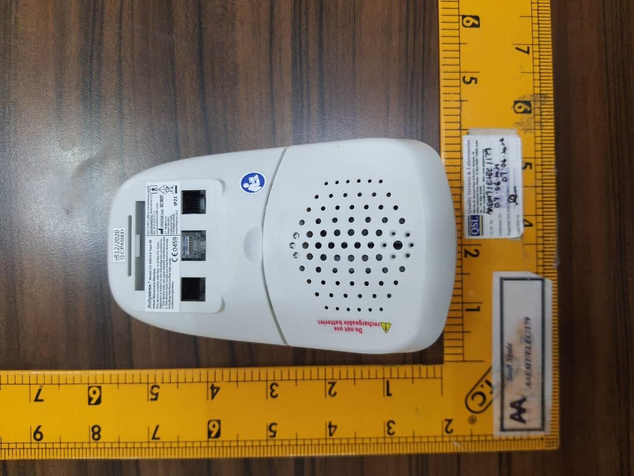
Click to zoom
Application Details
- Equipment Class
- DTS - Digital Transmission System
- Date of Grant
- Jul 08, 2021
- Application Purpose
- Original Equipment
- Date of Application
- Jul 08, 2021
- Equipment Note
- Babysense Connect (Babysense 7 Revision B)
- Frequency Range
- 2402.00000000 - 2480.00000000
- Company
- Hisense Ltd.,
- Country
- Israel
Documents & Files
Document Text
Text extracted from the exhibit documents filed with the FCC. Open a document above to read the original.
Users Manual
BABYSENSE CONNECT SAFE SLEEP INFANT BREATHING MONITOR User Manual BABYSENSE CONNECT SAFE SLEEP INFANT BREATHING MONITOR Ensure you read this user manual before installing and using the product. Babysense is a high quality, high sensitivity electronic device, which must be handled with care: Do not handle roughly, drop or throw. Follow the installation instruction carefully to ensure the device is installed securely and correctly. Babysense is not a toy. Do not allow children of any age to play with it. Do not put any additional baby or pet in the bed. Babysense Connect is intended for use with one infant and cannot be used for two infants in one bed. Babysense Connect cannot be used with co-sleepers that are attached to the parent's/caregiver's bed. Do not operate the unit in the presence of electromagnetic interference. Portable and mobile RF communications equipment may effect operation of this device. You must undertake the performance test daily and every time you move the monitor, change bedding or relocate crib/bed position (Daily Performance Test Section). Do not operate vaporizer or ventilator directly towards the bed. To avoid possible danger from sensor cords, ensure that excess cords are pulled back under the mattress, secured with the included cable tie and are not visible or reachable. Install 4 new and identical Alkaline size AA 1.5 volt batteries. DO NOT use rechargeable batteries. IMPORTANT: It is strongly advised that parents and caregivers learn how to give first aid. Please remove batteries if the device is not in use for an extended time (2 weeks or more). If you have any problems with this device, such as setting up, maintaining or using, please contact the manufacturer’s service personnel. Also, please report to the manufacturer if any unexpected operation or events occur. Do not use the equipment if you notice a change in the system's performance, if the system is damaged, or if any of its components are worn or frayed. The equipment should not be used adjacent to or stacked with other equipment. If adjacent or stacked use is necessary, the equipment should be observed to verify normal operation in the configuration in which it is used. Use only Babysense Connect sensor pads. Using different manufacturer sensors may damage Babysense's control unit and harm its performances. Babysense monitors and alerts, but cannot prevent any type of distress. The responsibility for applying first aid rests on caretakers. The Babysense senses breathing movements and motion only, and cannot monitor other occurrences. The purpose of the device is to alert when stopping or slowing of breathing and movement occur. Babysense is a unique safety system which has helped save infants, giving parents (or caregivers) assurance, by enabling intervention in the event of irregular breathing movement or distress, before it becomes critical. There are a number of cautionary steps, which are internationally recommended for SAFE SLEEPING: * Always lay baby to sleep on his or her back. * Refrain from smoking near or around baby. * Avoid over-heating of baby's surrounding. * Do not leave any objects near your baby that can cause suffocation. Babysense Connect is an addition to these precautions. Babysense Connect is a home movement monitor for infants up to one year of age, and is not to be used with high-risk infants requiring constant medical supervision. Medically trained staff such as nurses, or non-medically trained users such as parents or caregivers may use the Babysense Connect. Babysense Connect is intended for home use. Babysense continually detects baby's motion and breathing movements and will set off a sound and visual alarm if movement stops within 20 seconds or if the breathing rate slows to below 10 breaths per minute per minute. The system's non-touch, under the mattress sensor pads monitor baby's movement without restraining him. 1. To insert the batteries, remove the battery cover by placing your thumb/finger in the opening recess and gently pulling away from the control unit (see illustration 7). Insert, in accordance with the markings, 4 new and identical Alkaline size AA 1.5 volt batteries and close cover. Note: Please dispose of used batteries in accordance with local waste regulations. Note: Once batteries are inserted the Blue LED will flash 3 times indicating that BLE is activated. If the Red LED flashes 3 times it indicates an internal system error (please contact the manufacturer at [email protected]). 2. Place control unit holder on the base of the crib or bed and in between two bars as shown in illustration 1. 3. Sensor pad installation: In a crib/bed the 2 sensor pads need to be placed 15cms apart from each other. Locate the center of the crib and place each sensor pad 7.5cms away from the center In a bassinet the sensor pads should be placed side-by-side See illustration 2 PLEASE NOTE: The sensors should be placed with the marking "THIS SIDE UP" facing up. 4. If the mattress cannot be in contact with the sensor pads, or when using a crib/bed equipped with spring base, soft base or padded base, place extra wooden board (plywood) under each sensor pad, as shown in illustration 3. The recommended size of the board is at least 17’’ x 11’’ and 1/2’’ thick. 5. Pass the cords of the sensor pads through special openings in the holder (see illustration 4). 6. Attach sensor pad connectors to the outlets marked "SENSOR" on the back of control unit (see illustration 5 and 6). PLEASE NOTE: Do not attach any cable to the blocked socket, marked "DO NOT USE" (see illustration 7) 7. Should the design of the crib not allow proper installation with the control unit holder, please use the supplied hanging hook (see illustration 6). Hang the control unit from the bottom edge of the crib or affix the hook with a screw (not supplied) to the bottom edge of the crib and hang the control unit from the bottom edge of the crib. Lower LED Upper LED: 8. Press control unit holder or hang…
Text truncated - open the document above for the full version.
Cover Letter(s)
1/1 Office of Engineering Technology Federal Communications Commission 7435 Oakland Mills Road Columbia, MD 21046 Date: 22/06/2021 Subject: Request for Confidentiality FCC ID: 2AZL5-CU100-2F To Whom It May Concern, Pursuant to the provisions of Sections 0.457 and 0.459 of Commission's rules (47CFR0.457, 0.459), we are requesting the Commission to withhold the following attachment(s) as confidential document from public disclosure. Exhibits Long-Term Confidentiality Short-Term Confidentiality NOTE 2 ID Label/Location No No Attestation Statement No No External Photos No ☒ Block Diagram ☒ ☐ Schematics ☒ ☐ Test Report No No Test Setup Photos No ☒ User’s Manual ☐ NOTE 1 ☒ Internal Photos ☐ NOTE 1 ☒ Parts List / Tune Up ☒ ☐ RF Exposure Info No No Operational Description ☒ ☐ Cover Letter(s) No No SDR Software / Security Info ☒ No NOTE 1: Long-Term Confidentiality may be permitted under special conditions (See II. LONG-TERM CONFIDENTIALITY, Section 3 of KDB 726920, use last in force) NOTE 2: Short-Term Confidentiality can be requested for a maximum of 180 days from the date of the grant. Above mentioned document contains detailed system and equipment description are considered as proprietary information in operation of the equipment. The public disclosure of above documents might be harmful to our company and would give competitor an unfair advantage in the market. In case of short-term Confidentiality, the applicant requests the exhibits selected above are withheld from public view for a period of ___180___ days from the date of the Grant of Equipment Authorization and prior to marketing. It is our understanding that all measurement test reports, FCC ID label format and correspondent during certification review process cannot be granted as confidential documents and those information will be available for public review once the grant of equipment authorization is issued. Sincerely, Signature: Name: Natalie Shukrun Title: QA & RA Manager
Cover Letter(s)
Agent Authorization Company: Hisense Ltd. Address: 27 Shaked Street HevelModi’in Industrial Park 731990 Israel Product Name: Babysense Connect (Babysense 7 Revision B) Model Number(s): CU-100/2-F Product Description: Babysense 7 revision B (Babysense Connect) is an electrical device for the domestic customer that tracks the baby's breathing and heart rate. Baby monitor system comprises 3 units - a control unit (that is placed on the baby's bed and is visible to parents and caregivers), connected to 2 sensor pads (that are placed beneath the baby's mattress). The control unit is battery powered, by 4 nonchargeable AA alkaline batteries. System: Control unit connected by a cable to a sensor (located under the mattress). Control unit sends data to a mobile application via BLE technology. The sensor is connected to a control unit which analyses the incoming signals. If the monitor analyzes there is no movement, the control unit triggers both acoustic and visual alarms We authorize MiCOM Labs Inc., 575 Boulder Court, Pleasanton, California 94566, USA, to act on our behalf on all matters concerning the certification of above named equipment. We declare that MiCOM Labs Inc. is allowed to forward all information related to the approval and certification of equipment to the regulatory agencies as required and to discuss any issues concerning the approval application. Any and all acts carried out by MiCOM Labs on our behalf shall have the same effect as acts of our own. Signature: Date: 23-06-2021 Name: Natalie Shukrun Title: QA & RA Manager Company: Hisense Ltd.
External Photos
EXTERNAL PHOTOGRAPHS
ID Label/Location Info
PRODUCT LABEL LABEL ON EUT
Internal Photos
INTERNAL PHOTOGRAPHS BT 2.4G Antenna Port
RF Exposure Info
RF EXPOSURE EVALUATION 1. PRODUCTINFORMATION Product Description Babysense Connect (Babysense 7 Revision B) Model Name CU-100/2-F FCC ID 2AZL5-CU100-2F 2. EVALUATION METHODANDLIMIT Human exposure to RF emissions from mobile devices(47CFR§2.1091) may be evaluated based on the MPE limits adopted by the FCC for electric and magnetic field strength and/or power density, as appropriate, since exposures are assumed to occur at distances of 20 cm or more from persons. The device under test (Babysense Connect (Babysense 7 Revision B)) is neither a mobile device nor a RF exposure product and it is not closed to 20cm distance from persons LIMITS FOR GENERAL POPULATIONIUNCONTROLLED EXPOSURE Frequency Range (MHz) E-field Strength (E) (V/m) Magnetic Field Strength (H) (A/m) Power Density(S) (mW/cm 2 ) Averaging Time IEl 2 IHl 2 or , S(Minutes) 0.3--1.34 614 1.63 (100)* 30 1.34--30 824/f 2.19/f (180/f 2 )* 30 30--300 27.5 0.073 0.2 30 300--1500 -- -- f/1500 30 1500--100,000 -- -- 1.0 30 *Note: 1. f= Frequency in MHz*Plane-wave EquivalentPower Density 2. The averaging time for General Population/Uncontrolled exposure to fixed transmitters is not applicable for mobile and portable transmitters. (operated in BT/ WIFI) See47CFR§§2.1091 and 2.1093 on source-based time-averaging requirement for mobile and portabletransmitters. S=PG/4rrR 2 Where: S=power density P=power input toantenna G=power gain of the antenna in the direction of interest relative to anisotropic radiator R=distance to the center of radiation of the antenna 3. CALCULATION A minimum test separation distance 20cm is required between the antenna and radiating structures of the device and nearby persons to apply mobile device exposure limits. The distance must be at least 20cm and fully supported by the operating and installation configurations of the transmitter and its antenna(s), according to the source-based time-averaged maximum power requirements of §2.1091(d)(2). In cases where cable losses or other attenuations are applied to determine compliance, the most conservative operating configurations and exposure conditions must be evaluated. The device under test (Emporia Vue Energy Meter) is neither a mobile device nor a RF exposure product and it is not closed to 20cm distance from persons Antenna Gain (2.4GHz) = 0dBi (Numeric = 1), rr = 3.14 Frequency (MHz) Output Power (dBm) Output Power (mW) Power Density (mW/cm 2) PowerDensity Limit (mW/cm 2) 2480 3.25 2.1134890398 0.0004 1 Note: Only the worst case recorded.
Test Report
AA Electro Magnetic Test Laboratory Private Limited Certificate#5593.01 Report No.: AAEMT-EMC-210326-01-02 Page 1 of 45 Plot 174, Udyog Vihar Phase 4, Sector -18, Gurgoan, Haryana, India. Contact:0124-4235350,4145343;e-mail:[email protected];Website: www.aaemtlabs.com FCC Verification Test Report Client Information: Applicant: Hisense Ltd. Applicant add.: 27 Shaked Street, HevelModi’in Industrial Park, Israel - 731990 Product Information: EUT Name: Babysense Connect (Babysense 7 Revision B) Model No.: CU-100/2-F Brand Name: FCC ID: 2AZL5-CU-100/2-F Standards: FCC PART 15 Subpart C: 2013 section 15.247 Prepared By: Vaishali AA Electro Magnetic Test Laboratory Private Limited Add. : Plot No 174, Udyog Vihar - Phase 4, Sector 18, Gurgaon, Haryana, India Date of Receipt: March. 26, 2021 Date of Test: May. 24~ May. 27, 2021 Date of Issue: Jun. 01, 2021 Test Result: Pass Declaration of Conformity: This device described above has been tested by AA Electro Magnetic Test Laboratory Private Limited, and the test results show that the equipment under test (EUT) is in compliance with the FCC requirements. And it is applicable only to the tested sample identified in the report. *This test report must not be used by the client to claim product endorsement by any agency of the U.S. government. Reviewed by: Approved by: ( Dr. Lenin Raja) (Authorized Representative) (/ lenin83/) (Abhinav Kumar) Declaration of conformity of the results is based as per the standard limits FCC ID: 2AZL5-CU100-2F AA Electro Magnetic Test Laboratory Private Limited Certificate#5593.01 Report No.: AAEMT-EMC-210326-01-02 Page 2 of 45 Plot 174, Udyog Vihar Phase 4, Sector -18, Gurgoan, Haryana, India. Contact:0124-4235350,4145343;e-mail:[email protected];Website: www.aaemtlabs.com 1 Contents Page COVER PAGE 1 CONTENTS ..................................................................................................................................................................... 2 2 TEST SUMMARY ........................................................................................................................................................... 4 2.1 COMPLIANCE WITH FCC PART 15 SUBPART C .............................................................................................................. 4 2.2 TEST LOCATION .......................................................................................................................................................... 5 2.3 MEASUREMENT UNCERTAINTY .................................................................................................................................... 5 3 TEST FACILITY ............................................................................................................................................................. 6 3.1 DEVIATION FROM STANDARD ...................................................................................................................................... 6 3.2 ABNORMALITIES FROM STANDARD CONDITIONS ........................................................................................................... 6 4 GENERAL INFORMATION .......................................................................................................................................... 7 4.1 GENERAL DESCRIPTION OF EUT .................................................................................................................................. 7 4.2 DESCRIPTION OF TEST CONDITIONS .............................................................................................................................. 9 4.3 TEST PERIPHERAL LIST ............................................................................................................................................. 10 4.4 EUT PERIPHERAL LIST .............................................................................................................................................. 10 5 EQUIPMENTS LIST FOR ALL TEST ITEMS ........................................................................................................... 11 6 TEST RESULT .............................................................................................................................................................. 13 6.1 ANTENNA REQUIREMENT .......................................................................................................................................... 13 6.1.1 Standard requirement ....................................................................................................................................... 13 6.1.2 EUT Antenna ................................................................................................................................................... 13 6.2 CONDUCTION EMISSIONS MEASUREMENT .................................................................................................................. 14 6.2.1 Applied procedures / Limit ............................................................................................................................... 14 6.2.2 Test procedure ................................................................................................................................................. 14 6.2.3 Test results(Worst Case) .................................................................................................................................. 15 6.3 RADIATED EMISSIONS MEASUREMENT....................................................................................................................... 16 6.3.1 Applied procedures / Limit ............................................................................................................................... 16 6.3.2 Test setup ........................................................................................................................................................ 16 6.3.3 Test procedure .....................................…
Text truncated - open the document above for the full version.
Test Setup Photos
Radiated Spurious Emission Test Setup
Contact Information
Applicant
Natalie Shukrun(QA & RA Manager)
Technical Contact
Hisense Ltd.
India
Test Firm
AA Electro Magnetic Test LaboratoryJackie Deng
[email protected]911244235350
Technical Specifications
| # | Rule Parts | Frequency Range | Power Output |
|---|---|---|---|
| 1 | 15C | 2.40 GHz - 2.48 GHz | 2.10 mW |
Other Applications from Hisense Ltd.,
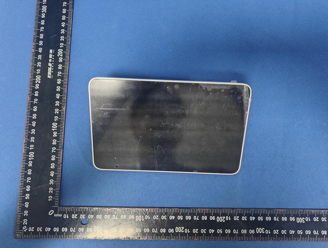
2AZL5-VDM70PU
Feb 10, 2026smart baby monitor/video baby monitor
Equipment Class
DTS - Digital Transmission System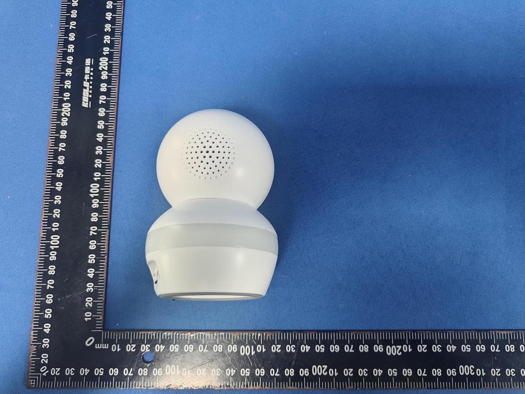
2AZL5-VDM70BU
Feb 10, 2026smart baby monitor/video baby monitor
Equipment Class
DTS - Digital Transmission System