2AZT3-701XB01Base Station
701x, Inc.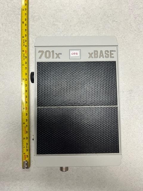
Click to zoom
Application Details
- Equipment Class
- DTS - Digital Transmission System
- Date of Grant
- May 03, 2023
- Application Purpose
- Original Equipment
- Date of Application
- May 03, 2023
- Equipment Note
- Base Station
- Frequency Range
- 2402.00000000 - 2480.00000000
- Company
- 701x, Inc.
- Country
- United States
Documents & Files
Document Text
Text extracted from the exhibit documents filed with the FCC. Open a document above to read the original.
Users Manual
xBase User Manual Getting Started Downloading the 701x App To interface with xBase, download the 701x app from the App Store or Google Play Store and install it onto your phone. Setting Up xBase Follow the steps below to set up your xBase for the first time. 1. Open the 701x app and follow the on- screen prompts to create an account. Then, log in to the account. 2. Scan the 3D barcode on the front of the tag. The tags information will automatically populate into your app. 3. Assign the xBase to the point of interest it will be mounted to. 4. Mount the device such that the solar panel will be in direct sun. 5. If using the external power adapter, plug the adapter into the device. 701x Information 701x 700 Main Ave. Fargo, ND 58104 www.701x.com [email protected] Implementing AG Compliance This device complies with part 15 of the FCC Rules. Operation is subject to the following two conditions: (1) This device may not cause harmful interference, and (2) this device must accept any interference received, including interference that may cause undesired operation. NOTE: This equipment has been tested and found to comply with the limits for a Class B digital device, pursuant to part 15 of the FCC Rules. These limits are designed to provide reasonable protection against harmful interference in a residential installation. This equipment generates, uses and can radiate radio frequency energy and, if not installed and used in accordance with the instructions, may cause harmful interference to radio communications. However, there is no guarantee that interference will not occur in a particular installation. If this equipment does cause harmful interference to radio or television reception, which can be determined by turning the equipment off and on, the user is encouraged to try to correct the interference by one or more of the following measures: —Reorient or relocate the receiving antenna. — Increase the separation between the equipment and receiver. —Connect the equipment into an outlet on a circuit different from that to which the receiver is connected. —Consult the dealer or an experienced radio/TV technician for help. Changes or modifications may void the user’s authority to operate the equipment. Please ensure at least 20 cm separation from the user when the device is in use.
Attestation Statements
1 www.701x.com 700 Main Ave Fargo, ND 58103 Certification Application Attestation Statements Date: April 3, 2023 American Certification Body, Inc. 313 Park Avenue Suite 300 Falls Church, VA 22046 To Whom It May Concern: Statement for 47 CFR section 2.911(d)(5)(i) 701x Inc certifies that as of the date of the application the equipment for which authorization is sought is not “covered” equipment 1 prohibited from receiving an equipment authorization pursuant to section 2.903 of the FCC rules. If the equipment for which the applicant seeks authorization is produced by any of the entities identified on the current Covered List, including affiliates or subsidiaries of the named companies, the applicant must include an explanation on why the equipment is not “covered” equipment. Additional Explanation: <N/A> Statement for 47 CFR section 2.911(d)(5)(ii) 701x Inc (“the applicant”) certifies that, as of the date of the filing of this application, the applicant is not identified on the Covered List as an entity producing “covered” equipment. Thank you, By: __________________________ ____Braydon Love______________ (Signature) (Print Name) Title: Certification Engineer Company: 701x Inc Telephone: 218-303-7779 1 - The Commission’s Covered List is published by the Public Safety and Homeland Security Bureau and posted on the Commission’s website. This Covered List, which is periodically updated, identifies particular equipment, produced by particular entities, that constitutes “covered” equipment. https://www.fcc.gov/supplychain/coveredlist .
Attestation Statements
1 www.701x.com 700 Main Ave Fargo, ND 58103 U.S. Agent Designation for Service of Process (Applicant is Both Grantee and U.S. Agent) TO: American Certification Body, Inc. 313 Park Avenue Suite 300 Falls Church, VA 22046 ATTENTION: FCC Certification – Section 2.911(d)(7) Information This letter is to confirm that the Applicant will also serve as the U.S. Agent for Service of Process as required by 47 CFR 2.911(d)(7). The Applicant acknowledges that they must maintain an agent for no less than one year after terminating all marketing and importation OR the conclusion of any Commission-related proceeding involving the equipment. The Applicant further acknowledges their responsibility to inform the FCC whenever the Designated U.S. Agent information changes. Applicant Company name: 701x Inc FRN #: 0030251326 Grantee Code: 2AZT3 Contact Name: Braydon Love Street Address: 700 Main Ave City/Province/Zip: Fargo, ND 58103 Telephone No: 218-303-7779 Email: [email protected] Applicant Signature: Date: 4/3/2023 Signed by (Printed Name/Title): Braydon Love, Certification Engineer
Cover Letter(s)
www.701x.com 700 Main Ave Fargo, ND 58103 Authority to Act as Agent Date: October 24, 2022 American Certification Body, Inc. 6731 Whittier Avenue Suite C110 McLean, VA 22101 To Whom It May Concern: Nic Johnson of the Nebraska Center for Excellence in Electronics (NCEE Labs) is authorized to act on our behalf, until otherwise notified, for applications to American Certification Body, Inc. (ACB). We certify that we are not subject to denial of federal benefits, that includes FCC benefits, pursuant to Section 5301 of the Anti-Drug Abuse Act of 1988, 21 U.S.C. 862. Further, no party, as defined in 47 CFR 1.2002 (b), to the application is subject to denial of federal benefits, that includes FCC benefits. We also declare that the information provided to the FCC is true and correct to the best of our knowledge (47 CFR 2.911(d)) and we have been informed of the grantee responsibilities (47 CFR 2.909) with regard to certified equipment. Thank you, Agency Agreement Expiration Date: _October 24 th , 2023_________ By: __________________________ Braydon Love_________ (Signature) (Print name) Title: Engineer___________________ On behalf of: 701x, Inc.___________________ (Company Name) Telephone: (218) 303-7779__________________
Cover Letter(s)
1(1) www.701x.com 700 Main Ave Fargo, ND 58103 March 15th, 2023 Attention: Application Examiner RE: Request for Confidentiality Applicant: 701x, Inc FCC ID: 2AZT3-701XB01 To Whom It May Concern: Request is hereby submitted by 701x, Inc to withhold permanently from public review certain portions of the application for equipment certification for the referenced FCC identifiers. This request for confidentiality is made pursuant to 47 CFR 0.457(d) and 0.459 of the FCC Rules. In particular, the following sections of the application are to be kept permanently confidential: • Schematics • Detailed Block Diagrams • Detailed Operational/Functional Description These items contain detailed system and equipment description and related information about the product which 701x considers to be proprietary, confidential and a custom design which otherwise would not be released to the general public. Since this design is a basis from which future technological products will evolve, 701x also feels that this information would be of benefit to its competitors, and that the disclosure of the information in these exhibits would give our competitors an unfair advantage in the market. Sincerely, Braydon Love Certification Engineer 701x
Cover Letter(s)
RE: 701x, Inc. FCC ID: 2AZT3-701XB01 Exhibit Label.pdf – i. Please provide label materials details (i.e. paper label, adhesives, etched, etc); ii. EUT appears to be large enough to contain the FCC Part 15.19 statement, please address accordingly; RESPONSE: The label material is etched into the plastic using a laser marking method. For 4ii. we would prefer to not place the statement on the label. Exhibit User Manual.pdf – Are there any user instructions for the base station? Is everything listed in the app? There are no instructions or details regarding the transmitters. Response: All setup instructions will be in the app. The device comes automatically configured for radio operations and the user is not required to perform much setup process other than mounting it, and "assigning" it to a point of interest in their app.
External Photos
EXTERNAL PHOTOS EXTERNAL PHOTOS EXTERNAL PHOTOS EXTERNAL PHOTOS EXTERNAL PHOTOS EXTERNAL PHOTOS
ID Label/Location Info
xBase FCC Label Location FCC ID: 2AZT3-701XB01 Size 16 font
Internal Photos
INTERNAL PHOTOS 2.4 GHz antenna Cellular antenna INTERNAL PHOTOS INTERNAL PHOTOS INTERNAL PHOTOS Note: black cable with SMA connector was for testing purposes only. It will not be present in production mdoels.
RF Exposure Info
xBase Operational Description Document Revision: R1.1 Last Revised: 4/18/23 700 Main Ave, Fargo, ND 58103 www.701x.com xBase Operational Description 1 Revision History Revision Number Change Description Revision Date Author R1.0 Initial Release 4/04/2023 BWL R1.1 Added section 3.1: Cellular Radio Operations 4/18/2023 BWL xBase Operational Description 2 Introduction The purpose of this document is to describe the operations of the xBase. The xBase is a battery powered Bluetooth Low Energy device that uses a 2.4 GHz radio for wireless communications. The radio uses Bluetooth Low Energy in the 2400 – 2500 MHz ISM band. The Texas Instruments CC2640R2L, operates the 2.4 GHz radio. The xBase uses a Quectel BG77 cellular module for GNSS and cellular communications. A primary non-rechargeable battery is used to power the device. The device has an additional sensor on the board to provide telemetry data over the wireless interfaces. 3 Radio Operations 3.1 2.4 GHz Radio Operation The CC2640R2L provides the device with Bluetooth Low Energy radio operations in the 2.4 GHz ISM band. The CC2652R7 is powered from a 3.3V lithium battery. The system is charged via a solar cell or has a 5-17VDC optional input for charging the battery. The CC2640R2L has a differential RF output. The max transmit power is 5 dBm. This differential output is fed to a discrete balun towards a chip antenna. The chip antenna has a gain of 1.1 dBi. The 2.4GHz interface uses 40 channels, each separated by 2 MHz. Each channel transmits with an approximate 1 MHz, 6dB bandwidth, signal. The channels used by the device can be found in Table 1 below. All wireless communication follows the Bluetooth Low Energy standard. Table 1: BLE Channels Channel Frequency (MHz) Channel Frequency (MHz) Channel Frequency (MHz) 0 2404 16 2438 32 2470 1 2406 17 2440 33 2472 2 2408 18 2442 34 2474 3 2410 19 2444 35 2476 4 2412 20 2446 36 2478 5 2414 21 2448 37 2402 6 2416 22 2450 38 2426 7 2418 23 2452 39 2480 8 2420 24 2454 9 2422 25 2456 10 2424 26 2458 11 2428 27 2460 12 2430 28 2462 13 2432 29 2464 14 2434 30 2466 15 2436 31 2468 xBase Operational Description 3.2 Cellular Radio Operation The Quectel BG77 provide GNSS and LTE cellular communications capabilities to the device. The Quectel BG77 is an FCC recertified cellular module (FCC ID: XMR201912BG77). The BG77 is powered from the 3.3V lithium battery. The cellular module operates on Verizon LTE bands 13 and 4. They operate on 776 - 787 MHz and 1710 – 1755 MHz frequency band respectively. The cellular module has a maximum transmit power of 21 dBm. The cell module uses the Pulse W3796 chip antenna with an average gain of -2.5 dBi for band 13 and -2 dBi for band 4. While not common, it is possible for both the cellular module and the 2.4 GHz radio to transmit at the same time.
Test Report
Description: 2.4-2.4835GHz Ceramic SMT antenna, 4x4.25mm keep out area PART NUMBER: W3008 Series: Chip Antenna Issue: 1946 In the effort to improve our products, we reserve the right to make changes judged to be necessary. CONFIDENTIAL AND PROPRIETARY INFORMATION This document contains confidential and proprietary information ofPulse Electronics, Inc. (Pulse) and is protected by copyright, trade secret and other state and federal laws. Its receipt or possession does not convey any rights to reproduce, disclose its contents, or to manufacture, use or sell anything it may describe. Reproduction, disclosure or use without specific written authorization of Pulse is strictly forbidden. For more information: Pulse Worldwide HeadquartersPulse/Larsen AntennasEurope HeadquartersPulse (Suzhou) Wireless Products Co, Inc. 15255 Innovation Drive #100Pulse GmbH & Do, KG99 HuoJuRoad(#29 Bldg,4 th Phase San Diego, CA 92128Vancouver, WA 98683Zeppelinstrasse15Suzhou New District USAUSAHerrenberg, Germany Jiangsu Province, Suzhou 215009 PR China Tel:1-858-674-8100Tel: 1-360-944-7551 - Tel: 49 7032 7806 0 Tel: 86 512 6807 9998 18110 SE 34 th St Bldg2 Suite 250 Features: Applications: All dimensions are in mm / inches •2400-2483.5MHz •Size: 3.2 x 1.6 x 1.1mm •Efficiency: 66 % •Gain: 1.1 dBi •Polarization: Linear •Power Handling: 5W •RoHS Compliant •Moisture Sensitivity Level MSL1 •Bluetooth, BLE, Zigbee, WiFi •2.4GHz ISM band radios 1 Issue: 1946 In the effort to improve our products, we reserve the right to make changes judged to be necessary. CONFIDENTIAL AND PROPRIETARY INFORMATION This document contains confidential and proprietary information ofPulse Electronics, Inc. (Pulse) and is protected by copyright, trade secret and other state and federal laws. Its receipt or possession does not convey any rights to reproduce, disclose its contents, or to manufacture, use or sell anything it may describe. Reproduction, disclosure or use without specific written authorization of Pulse is strictly forbidden. Description: 2.4-2.4835GHz Ceramic SMT antenna, 4x4.25mm keep out area PART NUMBER: W3008 Series: Chip Antenna 2 Frequency2400-2483.5MHz NominalImpedance50 Return Loss-4dB Radiation PatternOmni Gain1.1dBi Efficiency66% Polarizationlinear Power Withstanding5W MECHANICALSPECIFICATIONS ENVIRONMENTAL SPECIFICATIONS ELECTRICAL SPECIFICATIONS Operating Temperature-40~+85°C Storage Temperature-40~+85°C RoHS CompliantYes (*) All RF parameters measured on 80*37mm PCB with 4*4.25mm clearance in free space. No matching component used. Weight 0.03 g Overall Length 3.2 [0.126]MM [INCHES] Overall width 1.6 [0.063] MM [INCHES] Over all thickness 1.1 [0.043] MM [INCHES] MSL (Moisture Sensitivity Level) 1 Issue: 1946 In the effort to improve our products, we reserve the right to make changes judged to be necessary. CONFIDENTIAL AND PROPRIETARY INFORMATION This document contains confidential and proprietary information ofPulse Electronics, Inc. (Pulse) and is protected by copyright, trade secret and other state and federal laws. Its receipt or possession does not convey any rights to reproduce, disclose its contents, or to manufacture, use or sell anything it may describe. Reproduction, disclosure or use without specific written authorization of Pulse is strictly forbidden. Description: 2.4-2.4835GHz Ceramic SMT antenna, 4x4.25mm keep out area PART NUMBER: W3008 Series: Chip Antenna 3 No.Terminal NameTerminal Dimensions 1Feed /GND0.62 x 1.36 mm 2Feed /GND0.62 x 1.36 mm Antenna is symmetrical, either one of pads 1 or 2 can be used as feed terminal MECHANICAL DRAWING AND TERMINAL CONFIGURATION 1 2 Note:ThistypeofantennaiscalledloadedPIFA.Onepad(onthebottomoftheceramicchipantenna) thatfeedlineandGNDareconnectedisabasicPIFAantennastructure.And,anotherpadontheother sidethatonlyGNDisconnectedisforcapacitiveloading.Loadedcapacitivevalueisoptimizedbythegap distancebetweentwopadsonthetopsurface.InPIFA,thereisshortmechanismusuallyinproximityto feed.ThisRFshortingaffectsimpedanceandcurrentdistributionmechanismofantenna.Theactual antennatopfacecanseemtobemirrored,howeveritcanbeusedsameasthenon-mirroredversion. Pleasefollowthedesignrecommendationspecifiedinthisdatasheetforeithercase. Issue: 1946 In the effort to improve our products, we reserve the right to make changes judged to be necessary. CONFIDENTIAL AND PROPRIETARY INFORMATION This document contains confidential and proprietary information ofPulse Electronics, Inc. (Pulse) and is protected by copyright, trade secret and other state and federal laws. Its receipt or possession does not convey any rights to reproduce, disclose its contents, or to manufacture, use or sell anything it may describe. Reproduction, disclosure or use without specific written authorization of Pulse is strictly forbidden. Description: 2.4-2.4835GHz Ceramic SMT antenna, 4x4.25mm keep out area PART NUMBER: W3008 Series: Chip Antenna 4 MECHANICAL DRAWING AND TERMINAL CONFIGURATION Ground cleared under antenna, clearance area 4 mm x 4.25mm Issue: 1946 In the effort to improve our products, we reserve the right to make changes judged to be necessary. CONFIDENTIAL AND PROPRIETARY INFORMATION This document contains confidential and proprietary information ofPulse Electronics, Inc. (Pulse) and is protected by copyright, trade secret and other state and federal laws. Its receipt or possession does not convey any rights to reproduce, disclose its contents, or to manufacture, use or sell anything it may describe. Reproduction, disclosure or use without specific written authorization of Pulse is strictly forbidden. Description: 2.4-2.4835GHz Ceramic SMT antenna, 4x4.25mm keep out area PART NUMBER: W3008 Series: Chip Antenna 5 MECHANICAL DRAWING AND TERMINAL CONFIGURATION PCB contact pads No.Terminal NameTerminal Dimensions 1Feed 0,80 x 0,65 mm 2GND0,80x 0,65mm 3GND0,80 x 1,60 mm 1 2 3 Recommended Antenna Pad Dimensions on PCB Layout (top surface) Ground cleared under antenna, clearance area 4 mm x 4.25 mm Issue: 1946 In t…
Text truncated - open the document above for the full version.
Test Report
The Nebraska Center for Excellence in Electronics (NCEE) authorizes the above named company to reproduce this report provided it is reproduced in its entirety for use by the company’s employees only. Any use that a third party makes of this report, or any reliance on or decisions made based on it, are the responsibility of such third parties. NCEE accepts no responsibility for damages, if any, suffered by any third party as a result of decisions made or actions based on this report. This report applies only to the items tested. FCC/ISED Test Report Prepared for: 701x Inc. Address: 700 Main Avenue Fargo, North Dakota 58103 EUT: Ag Device xBASE Test Report No: R20230211-00-E1A Approved by: __________________ Nic Johnson, NCE Technical Manager iNARTE Certified EMC Engineer #EMC-003337-NE DATE: May 3, 2023 Total Pages: 38 Report Number: R20230211-00-E1 Rev A Prepared for: 701x Inc The Nebraska Center for Excellence in Electronics 4740 Discovery Drive Lincoln, NE 68521 Page 2 of 38 REVISION PAGE Rev. No. Date Description Original 30 March 2023 Issued by KVepuri Prepared by BWinter A 26 April 2023 Rev A – NJohnson Prepared by BWinter 1. List details of reference offset in plots in 4.5 and 4.6. 2. Add FCC ID and contained FCC ID in 2.1. Report Number: R20230211-00-E1 Rev A Prepared for: 701x Inc. The Nebraska Center for Excellence in Electronics 4740 Discovery Drive Lincoln, NE 68521 Page 3 of 38 CONTENTS Revision Page ....................................................................................................................................................................... 2 1.0 Summary of test results ....................................................................................................................................... 4 2.0 EUT Description .................................................................................................................................................... 5 2.1 Equipment under test .................................................................................................................................. 5 2.2 Description of test modes .......................................................................................................................... 6 2.3 Description of support units ...................................................................................................................... 6 3.0 Laboratory description......................................................................................................................................... 7 3.1 Laboratory description ............................................................................................................................... 7 3.2 Test personnel .............................................................................................................................................. 7 3.3 Test equipment ............................................................................................................................................. 8 3.4 General Test Procedure and Setup for Radio Measuremnts ............................................................... 9 4.0 Detailed results .................................................................................................................................................... 10 4.1 Duty Cycle ................................................................................................................................................... 11 4.2 Radiated emissions ................................................................................................................................... 12 4.3 Peak Output Power .................................................................................................................................... 20 4.4 Bandwidth ................................................................................................................................................... 23 4.5 Bandedges .................................................................................................................................................. 26 4.6 Power Spectral Density ............................................................................................................................. 30 4.6 Conducted AC Mains Emissions ............................................................................................................. 33 Appendix A: Sample Calculation ................................................................................................................................... 36 Appendix B – Measurement Uncertainty ...................................................................................................................... 37 REPORT END ..................................................................................................................................................................... 38 Report Number: R20230211-00-E1 Rev A Prepared for: 701x Inc. The Nebraska Center for Excellence in Electronics 4740 Discovery Drive Lincoln, NE 68521 Page 4 of 38 1.0 SUMMARY OF TEST RESULTS The EUT has been tested according to the following specifications: (1) US Code of Federal Regulations, Title 47, Part 15 (2) ISED RSS-Gen, Issue 5 (3) ISED RSS-247, Issue 2 ANSI C63.10-2013 was used as a test method, with guidance from KBD 558074 D01 v05 APPLIED STANDARDS AND REGULATIONS Standard Section Test Type Result FCC Part 15.203 Unique Antenna Requirement Internal Antenna FCC Part 15.35 RSS Gen, Issue 5, Section 6.10 Duty Cycle NA (100% duty cycle) FCC Part 15.247(b)(3) RSS-247 Issue 2 Section 5.4(d) Peak output power Pass FCC Part 15.247(a)(2) RSS-247 Issue 2 Section 5.2 Bandwidth Pass FCC Part 15.209 RSS-Gen Issue 5, Section 7.3 Receiver Radiated Emissions Pass FCC Part 15.209 (restricted bands), 15.247 (unrestricted) RSS-247 Issue 2 Section 5.5, RSS-Gen Issue 5, Section 8.9 Transmitter Radiated Emissions Pass F…
Text truncated - open the document above for the full version.
Test Setup Photos
TEST SETUP PHOTOS TEST SETUP PHOTOS TEST SETUP PHOTOS
Contact Information
Applicant
Braydon Love(Certification Engineer)
Test Firm
Nebraska Center for Excellence in ElectronicsKarthik Vepuri
Technical Specifications
| # | Rule Parts | Frequency Range | Power Output |
|---|---|---|---|
| 1 | 15C | 2.40 GHz - 2.48 GHz | 2.00 mW |
Other Applications from 701x, Inc.
2AZT3-701XCT1
Dec 18, 2022Agricultural Asset Tracker
Equipment Class
DXX - Part 15 Low Power Communication Device Transmitter