2AZUP-SP5268Wireless Procontroller for Switch
Shenzhen CHT Technology Co., Ltd.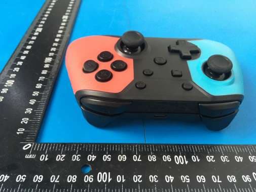
Click to zoom
Application Details
- Equipment Class
- DTS - Digital Transmission System
- Date of Grant
- May 19, 2021
- Application Purpose
- Original Equipment
- Date of Application
- May 19, 2021
- Equipment Note
- Wireless Procontroller for Switch
- Frequency Range
- 2402.00000000 - 2480.00000000
- Country
- China
Documents & Files
Document Text
Text extracted from the exhibit documents filed with the FCC. Open a document above to read the original.
Users Manual
Shenzhen CHT Technology Co., Ltd. Rev:1.4 first page A total of 7 pages Bluetooth Handle Product Specifications 1. Product description: This product belongs to Switch Pro Bluetooth game controller. It is connected to Switch host through Bluetooth communication and supports wired connection. 2. Product Features: (1) Include all the buttons and corresponding functions of the original Switch handle, and increase the function of adjusting continuous speed and motor vibration strength; (2) Provide 4 LED status indicators; (3)20 function keys input, "docking" button to facilitate the first pairing and shutdown; (4) Built-in double motors, high precision 3D rocker; (5) There are 4 mapping keys M1, M2, M3 and M4 on the back, with two groups of functions to choose from; (6) Equip with 6-axis gyroscope, fast and accurate target locking; (7) Compatible with PC host and support X_INPUT mode. Shenzhen CHT Technology Co., Ltd. Rev:1.4 first page A total of 7 pages + Key The action keyX The action key A Right rocker /R3 The action keyY TURBO key The action key B Type-C L3 direction key HOME status indicator —Key print screen Sys Rq ZR R ZL L M1 M3 M2 M4 Docking key Shenzhen CHT Technology Co., Ltd. Rev:1.4 first page A total of 7 pages 3. functional description 4. (2) Bluetooth connection to the Switch host: for the first use of the handle, long press the "docking" button of the handle for about 3 seconds, until the LED1-4 water light flickers after the handle is turned on, open the Switch host to the pairing interface for Bluetooth pairing, after the successful pairing, all functions of the handle can be used normally, the host allocation handle channel light is long on;If the match is not successful, the controller will automatically sleep after 60 seconds. 5. (3) Wired guided Bluetooth docking function: After the gamepad is connected to the Switch host via USB data cable, press any key of the gamepad to wake up, unplug the data cable, and the gamepad will automatically connect to the Switch host through Bluetooth; 6. (4) "Docking" button operation: long press the "Docking" button for 3 seconds in the hibernation state, the handle enters the Bluetooth pairing state with the host, LED1-4 state is the water light, and short press the "Docking" button in the startup state, the handle sleeps; 7. (5) The gamepad is connected to a PC through a USB cable, and the device display name is Xbox 360 Controller (the PC must have an Xbox 360 driver installed) to realize the function of Xbox 360 gamepad; 8. (6) Switch host upgrade function is not supported for the gamepad. To update the gamepad firmware, please download our company's program and upgrade it by connecting to PC. (If some functions of the gamepad cannot be used normally due to Switch host version upgrade, please contact our company to obtain the program and upgrade instructions for the gamepad firmware upgrade). 9. (7) The handle supports continuous sending function. After holding down A single function key (such as A, B, X, Y), press the "Turbo" key again, the function key has continuous sending function. If the continuous sending function of the key needs to be cancelated, repeat the above operation once.Press and hold the "Turbo" button of the handle to operate right 3D up and down at the same time. The speed of continuous firing can be adjusted in three gears: fast, medium and slow. 10. (8) The handle supports any key wakeup (except L3, R3, Turbo, M1, M2, M3, M4 keys). After wakeup, the handle enters the state of connecting back, LED1-4 is the flashing water light. If the handle is not matched with the Switch host before, it will connect back to the host. 11. (9) The button part of the joystick is composed of UP, DOWN, LEFT, RIGHT, A, B, X, Y, L, R, ZL, ZR, L3, R3, -, +, TURBO, HOME, screenshot, docking 20 function keys and 4 mapping keys M1, M2, M3, M4, equipped with LEFT and RIGHT 3D joystick; 12. (10) The handle is equipped with vibration function. In the "Settings" option of the Switch host, the motor vibration function of the handle can be turned on or off manually.The handle also supports the adjustment of vibration intensity. When the handle is connected, press and hold the "Turbo" button of the handle to conduct the left 3D up and down operation at the same time, which can enhance and weaken the motor vibration intensity. After operation, there will be a 3-second vibration prompt. 13. (11) There are four mapping keys M1, M2, M3 and M4 on the back of the handle, and there are four groups of states to choose from.The first three groups of states are mapping functions, the first group is M1-A, M2-B, M3-X, M4-Y, and the second group is M1-R, M2-L, M3-ZR, M4-Z.In the third group, both M1 and M3 were R3, and both M2 and M4 were L3. In the fourth group, M1, M2, M3 and M4 had no functional output.When connected to Switch host or PC, press and hold the "Turbo" button of the handle and then press the "-" button to Switch the four groups of states.When the handle leaves the factory, the function of the back mapping key defaults to M1-A, M2-B, M3-X and M4-Y. 14. 4. The charging Shenzhen CHT Technology Co., Ltd. Rev:1.4 first page A total of 7 pages 15. The channel light flashes when the adapter is inserted, and then the channel light goes off when it is fully charged. 16. When the handle is charging on line, the corresponding channel light will flash slowly and light long after it is full. 17. 5. Low power alarm 18. When the battery voltage of the handle is lower than 3.6V, the light of the corresponding channel flashes to indicate that the power of the handle is low and it is necessary to charge the handle. 19. 6. Standby 20. When the handle is in the power-on state, press the "docking" button to stand by. 21. When the handle is in the pairing state, it will automatically stand by when the code cannot be adjusted after 60 seconds. 22. 7. Reset function 23. When the handle is abnormal, it can be reset by pressing the "butt" button. 24. 8. Rece…
Text truncated - open the document above for the full version.
Cover Letter(s)
5/11/2021 Equipment Autorisation Division Federal Communications Commission 7435 Oakland Mills Road Columbia, MD 21046 FCC ID: 2AZUP-SP5268 Product Name: Wireless Procontroller for Switch Request for Confidentiality Pursuant to Sections 0.457 and 0.459 of the commissions rules, we hereby request that the following documents be held confidential: Schematics Long-term confidential Block diagram Long-term confidential Operation description Long-term confidential These materials contain trade secrets and proprietary information and are not customarily released to the public. The public disclosure of this information might be harmful to the company and provide unjustified benefits to our competitors. Signature: Name You Liang Chen Position general manager Company Name Shenzhen CHT Technology Co., Ltd. Address Building L, Shengguang Industrial Park, No. 152 Shajing DongHuan Road, XinQiao Street, Bao'An District, Shenzhen, China Tel 0755-23215379 Fax 0755-23215383 Email [email protected]
Cover Letter(s)
Differences Description We Shenzhen CHT Technology Co., Ltd. (Singapore) state: Product name: Wireless Procontroller for Switch Model: SP5246, SP5248, SP5268, SP5267 All model’s the function, software and electric circuit are the same, except the model numbers and appearance color difference. 2021-05-11 Name You Liang Chen Position general manager Company Name Shenzhen CHT Technology Co., Ltd. Address Building L, Shengguang Industrial Park, No. 152 Shajing DongHuan Road, XinQiao Street, Bao'An District, Shenzhen, China Tel 0755-23215379 Fax 0755-23215383 Email [email protected] (Signature)
External Photos
FCC ID: 2AZUP-SP5268 FCC ID: 2AZUP-SP5268 FCC ID: 2AZUP-SP5268 FCC ID: 2AZUP-SP5268 FCC ID: 2AZUP-SP5268
ID Label/Location Info
4.5cm 2.5cm 4.5cm 2.5cm 4.5cm 2.5cm 4.5cm 2.5cm FCC ID: 2AZUP-SP5268 Shenzhen CHT Technology Co., Ltd. Product name: Wireless Procontroller for Switch Model No.: SP5246 This device complies with Part 15 of the FCC Rules. Operation is subject to the following two conditions: (1) this device may not cause harmful interference, and (2) this device must accept any interference received, including interference that may cause undesired operation. FCC ID: 2AZUP-SP5268 Shenzhen CHT Technology Co., Ltd. Product name: Wireless Procontroller for Switch Model No.: SP5248 This device complies with Part 15 of the FCC Rules. Operation is subject to the following two conditions: (1) this device may not cause harmful interference, and (2) this device must accept any interference received, including interference that may cause undesired operation. FCC ID: 2AZUP-SP5268 Shenzhen CHT Technology Co., Ltd. Product name: Wireless Procontroller for Switch Model No.: SP5268 This device complies with Part 15 of the FCC Rules. Operation is subject to the following two conditions: (1) this device may not cause harmful interference, and (2) this device must accept any interference received, including interference that may cause undesired operation. FCC ID: 2AZUP-SP5268 Shenzhen CHT Technology Co., Ltd. Product name: Wireless Procontroller for Switch Model No.: SP5267 This device complies with Part 15 of the FCC Rules. Operation is subject to the following two conditions: (1) this device may not cause harmful interference, and (2) this device must accept any interference received, including interference that may cause undesired operation. Label Location
Internal Photos
FCC ID: 2AZUP-SP5268 FCC ID: 2AZUP-SP5268 FCC ID: 2AZUP-SP5268 FCC ID: 2AZUP-SP5268 Antenna
RF Exposure Info
FCC ID: 2AZUP-SP5268 RF Exposure evaluation According to 447498 D01 General RF Exposure Guidance v06 The 1-g and 10-g SAR test exclusion thresholds for 100 MHz to 6 GHz at test separation distances ≤ 50 mm are determined by: [(max. power of channel, including tune-up tolerance, mW)/(min. test separation distance, mm)] ·[√f(GHz)] ≤ 3.0 for 1-g SAR and ≤ 7.5 for 10-g extremity SAR, where f(GHz) is the RF channel transmit frequency in GHz Power and distance are rounded to the nearest mW and mm before calculation The result is rounded to one decimal place for comparison Worse case is as below: [2441MHz: 1.248 dBm (1.33 mW) output power] (1.33mW /5mm) ·[√2.441 (GHz)]= 0.42 <3.0 for 1-g SAR Then SAR evaluation is not required
Test Report
FCC TEST REPORT FCC ID: 2AZUP-SP5268 On Behalf of Shenzhen CHT Technology Co., Ltd. Wireless Procontroller for Switch Model No.: SP5246, SP5248, SP5268, SP5267 Prepared for : Shenzhen CHT Technology Co., Ltd. Address : Building L, Shengguang Industrial Park, No. 152 Shajing DongHuan Road, XinQiao Street, Bao’An District, Shenzhen, China Prepared By : Shenzhen Alpha Product Testing Co., Ltd. Address : Building i, No.2, Lixin Road, Fuyong Street, Bao’an District, 518103, Shenzhen, Guangdong, China Report Number : A2103076-C01-R01 Date of Receipt : April 13, 2021 Date of Test : April 13, 2021- May 7, 2021 Date of Report : May 8, 2021 Version Number : V0 Page 2 of 52 Report No.: A2103076-C01-R01 TABLE OF CONTENTS Description Page 1. Summary of Standards and Results ----------------------------------------------------------------- 6 1.1. Description of Standards and Results ---------------------------------------------------------- 6 2. General Information ------------------------------------------------------------------------------------ 7 2.1. Description of Device (EUT) -------------------------------------------------------------------- 7 2.2. Accessories of Device (EUT) ------------------------------------------------------------------- 8 2.3. Tested Supporting System Details -------------------------------------------------------------- 8 2.4. Block Diagram of connection between EUT and simulators ------------------------------- 8 2.5. Test Mode Description --------------------------------------------------------------------------- 8 2.6. Test Conditions ------------------------------------------------------------------------------------ 8 2.7. Test Facility ---------------------------------------------------------------------------------------- 9 2.8. Measurement Uncertainty ----------------------------------------------------------------------- 9 2.9. Test Equipment List ---------------------------------------------------------------------------- 10 3. Spurious Emission --------------------------------------------------------------------------------------11 3.1. Test Limits --------------------------------------------------------------------------------------- 11 3.2. Test Procedure ----------------------------------------------------------------------------------- 11 3.3. Test Setup ---------------------------------------------------------------------------------------- 12 3.4. Test Results -------------------------------------------------------------------------------------- 13 4. Power Line Conducted Emission ------------------------------------------------------------------- 19 4.1. Test Limits --------------------------------------------------------------------------------------- 19 4.2. Test Procedure ----------------------------------------------------------------------------------- 19 4.3. Test Setup ---------------------------------------------------------------------------------------- 19 4.4. Test Results -------------------------------------------------------------------------------------- 19 5. Conducted Maximum Output Power ------------------------------------------------------------- 22 5.1. Test limits ---------------------------------------------------------------------------------------- 22 5.2. Test Procedure ----------------------------------------------------------------------------------- 22 5.3. Test Setup ---------------------------------------------------------------------------------------- 22 5.4. Test Results -------------------------------------------------------------------------------------- 22 6. Power Spectral Density ------------------------------------------------------------------------------- 23 6.1. Test limits ---------------------------------------------------------------------------------------- 23 6.2. Test Procedure ----------------------------------------------------------------------------------- 23 6.3. Test Setup ---------------------------------------------------------------------------------------- 23 6.4. Test Results -------------------------------------------------------------------------------------- 23 7. Bandwidth ----------------------------------------------------------------------------------------------- 25 7.1. Test limits ---------------------------------------------------------------------------------------- 25 7.2. Test Procedure ----------------------------------------------------------------------------------- 25 7.3. Test Setup ---------------------------------------------------------------------------------------- 25 7.4. Test Results -------------------------------------------------------------------------------------- 25 8. Band Edge Check -------------------------------------------------------------------------------------- 29 8.1. Test limits ---------------------------------------------------------------------------------------- 29 8.2. Test Procedure ----------------------------------------------------------------------------------- 29 8.3. Test Setup ---------------------------------------------------------------------------------------- 29 8.4. Test Results -------------------------------------------------------------------------------------- 29 9. Antenna Requirement -------------------------------------------------------------------------------- 32 9.1. Standard Requirement -------------------------------------------------------------------------- 32 9.2. Antenna Connected Construction ------------------------------------------------------------- 32 Page 3 of 52 Report No.: A2103076-C01-R01 9.3. Results -------------------------------------------------------------------------------------------- 32 10. Test Setup Photo --------------------------------------------------------------------------------------- 33 10.1. Photos of Radiated emission ------------------------------------------------------------------ 33 10.2. Photos of Conducted Emission test ----------------------------------------------------------- …
Text truncated - open the document above for the full version.
Test Setup Photos
Test Setup Photo .Photos of Radiated emission Photos of Conducted Emission test
Contact Information
Applicant
You Liang Chen(general manager)
Test Firm
Shenzhen Alpha Product Testing Co., LTD.Simple Guan
[email protected]+86 755 29766001-810
Technical Specifications
| # | Rule Parts | Frequency Range | Power Output |
|---|---|---|---|
| 1 | 15C | 2.40 GHz - 2.48 GHz | 1.10 mW |
Other Applications from Shenzhen CHT Technology Co., Ltd.
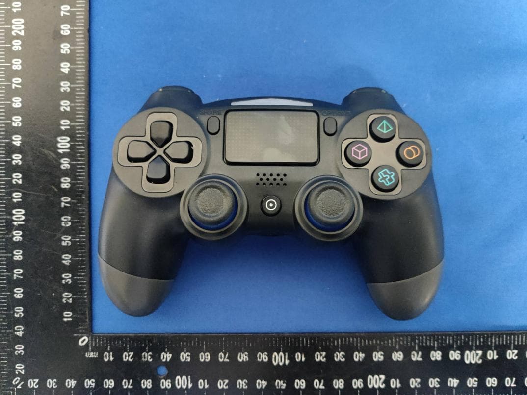
2AZUP-SP4236
Mar 28, 2023Wireless Game Controller for PS4
Equipment Class
DSS - Part 15 Spread Spectrum Transmitter