2BA4I-FX10Guitar Multi Effect
Shenzhen Flamma Innovation Co., Ltd.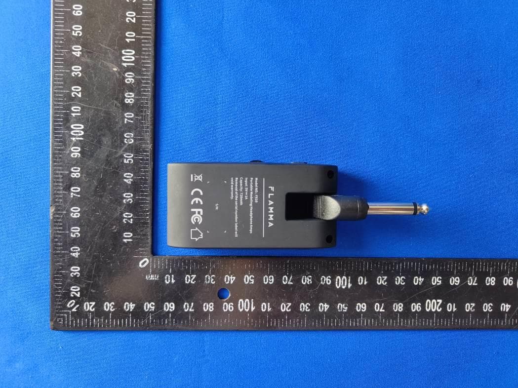
Click to zoom
Application Details
- Equipment Class
- DSS - Part 15 Spread Spectrum Transmitter
- Date of Grant
- May 16, 2023
- Application Purpose
- Original Equipment
- Date of Application
- May 16, 2023
- Equipment Note
- Guitar Multi Effect
- Frequency Range
- 2402.00000000 - 2480.00000000
- Country
- China
Documents & Files
Document Text
Text extracted from the exhibit documents filed with the FCC. Open a document above to read the original.
Users Manual
FX10 user manual Portable Modeling Headphone Amps 1. Features 14 different amp models with automatic save function 14 built-in effects with parameter adjustment 5 levels of TONE color 28 different drum groove options to select from Compatible with Bluetooth for audio playback Supports USB AUDIO recording and audio playback Layout 1 2 3 4 5 6 7 8 9 10 1. 1/4’’ instrument input jack. Connect to the output of the guitar. 2. Volume control: Rotate to adjust the volume level of the guitar and drum machine. 3. Three-way Power Switch. OFF: Power off. ON: Power on (Bluetooth off). BT ON: Bluetooth on. The power indicator will show current power status. 4. AMP button: Press to select AMP module (preset patch), then press the -/+ buttons to select between 14 different amp models. The color of LED indicator will show currently selected amp model. 5. TONE button: Press to select TONE module. Press -/+ buttons to switch between 5 different tone colors. 6. EFX button a. Press to select EFFECT module. Press the -/+ buttons to switch between different effects b. When the EFFECT module is selected, press the EFX button to bypass effect. c. When the EFFECT module is selected, press and hold the EFX button to enter hidden mode. 7. DRUM button a. Press DRUM to turn on the drum machine. You can press and hold DRUM to turn off the drum machine. The LED indicator will show the On/Off status of the drum machine. b. When drum machine is on, press DRUM to switch between three parameter adjustment modes. The color of the LED indicator will show current select mode: RED for drum groove, GREEN for volume level of drum machine, BLUE for speed of drum machine. You can adjust those parameters via -/+ button. 8. -/+ button: Adjust currently selected modules (AMP/TONE/EFX/DRUM). 9. 1/8” TRS headphone jack, connect to headphone device. 10. USB-C port for charging and OTG function (support USB audio recording and playback). 2. Instructions 1. Start Toggle the power switch to the ON position. The power indictor will illuminate and turn blue for when power is on. You can toggle the switch to Bluetooth icon to turn on Bluetooth Audio function. 2. Tone/Effect Adjustment a. Select amp model: Press AMP to select AMP module (preset patch), then press the -/+ buttons to select between 14 different amp models. The color of LED indicator will show currently selected amp model. b. Adjust tone color: Press TONE to select TONE module, then press -/+ buttons to switch between 5 different tone colors. c. Select EFX: Press EFX to select EFFECT module, then press the -/+ buttons to switch between different effects d. EFX adjustment: Each effect in the EFFECT module has a hidden parameter adjustment mode and the selected effect can be adjusted between 10 different levels. When EFFECT module is selected, press and hold EFX to enter hidden parameter adjustment mode, then press the -/+ buttons to adjust it. The color of LED indicator will show currently selected level. BUTTON COLOR VALUE 1 2 3 4 5 6 7 8 9 10 e. Bypass EFFECT: When the EFFECT module is selected (LED indicator is on), press the EFX button to bypass EFFECT module. f. Saving: When the parameter adjustment is complete, current tone will be saved into the currently selected AMP module as a preset patch, which includes AMP type, TONE color, EFX On/Off, EFX type, and EFX hidden parameter. Note: When a module (AMP/TONE/EFX) is selected, the corresponding LED indictor will illuminate completely, otherwise it will illuminate in half brightness. 3. Drum Machine a. Press DRUM to turn on the drum machine. You can press and hold the DRUM to turn off the drum machine, the LED indicator will show the On/Off status of drum machine. b. Select drum groove FX10 has 28 different drum grooves. When drum machine is on, press the DRUM to switch between three parameter adjustment modes. The color of the LED indicator will show the currently selected mode. RED indicates drum groove. Please refer to the groove list in the next session for use. c. Adjust volume level of drum machine When the DRUM is selected, press DRUM several times to enter volume level adjustment mode (LED indicator illuminate as GREEN). You can press the -/+ buttons to adjust the volume level of drum machine. Please refer to the color of LED indicator for adjustment. BUTTON COLOR VALUE 1 2 3 4 5 6 7 8 9 10 d. Adjust drum machine speed When the DRUM is selected, press the DRUM for several times to enter speed adjustment mode (LED indicator will blink as BLUE). Press -/+ button to adjust the speed via 1 BPM each time. Press and hold -/+ to increase or decrease the speed quickly. The speed of drum machine ranges from 40 BPM to 260 BPM. (状态跳转说明) 鼓机关闭:Drum Machine Off 节奏选择:Select Drum Groove 音量调节:Adjust volume level 速度调节:Adjust speed 短按:Press 长按:Press and hold 状态跳转说明:Drum machine operation diagram 鼓机关闭 节奏选择 音量调节 速度调节 短按 长按 4. Effect List a、 AMP: Number LED Color Reference 1 Fender® 65 Twin Reverb 2 Fender® 65 Deluxe Reverb 3 Acoustic guitar simulation 4 Fender® Super Sonic 5 Fender® 59 Bassman 6 DR.Z® Z-Wreck 7 Marshall® JCM800 8 Marshall® Plexi 9 VOX® AC30 10 ENGL® Powerball 11 Mesa Boogie® Mark V 12 Orange® AD 30 13 Soldano® SLO 100 14 EVH® 5150 III *NOTES: All product names belong to their owners and are only used in this product and manual as a reference to tone types. b、Tone Number LED Color Descriptions 1 Darker更暗 2 dark暗 3 Straightness平直 4 Bright明亮 5 Brighter更亮 c、EFX Number LED Color Descriptions Hidden Parameters 1 房间混响 Room Reverb 混响音量 Reverb Level 2 大厅混响 Hall Reverb 混响音量 Reverb Level 3 教堂混响 Church Reverb 混响音量 Reverb Level 4 板式混响 Plate Reverb 混响音量 Reverb Level 5 弹簧混响 Spring Reverb 混响音量 Reverb Level 6 调制混响 Mod Reverb 混响音量 Reverb Level 7 回声延迟 Slapback Delay 延迟音量 Delay Level 8 磁带延迟+大厅混响 Tape Dly+Hall 延迟音量 Delay Level 9 反向延迟+调制混响 Reverse Dly+ModReverb 延迟时间 Delay Time 10 乒乓延迟+教堂混响 PingPong Dly+Church 延迟时间 Delay Time 11 合唱+大厅混响 Chorus+Hall 调制深度 Mod Depth 12 移相+教堂混响 Phaser+Church 调制深度 Mod Depth 13 镶边+板式混响 Flanger+Plate 调制速率 M…
Text truncated - open the document above for the full version.
Attestation Statements
Shenzhen Flamma Innovation Co., Ltd. U.S. Agent Letter of Attestation To:FederalCommunicationsCommission 7435 Oakland Mills Road, Columbia, MD 21046, USA Date:May-12-2023 Ref: Attestation Statement – Part 2.911(d)(7) filing FCC ID: 2BA4I-FX10 Shenzhen Flamma Innovation Co., Ltd.(“the applicant”) certifies that, as of the date of the filing of the application, THREE STONES MEDIA LLC(“the agent”) is our designated U.S. agent for service of process for the abovereference FCC ID. The applicant accepts to maintain an agent for service of process in the United States forno less than one year after either the grantee has permanently terminated all marketing and importation of theapplicable equipment within the U.S., or the conclusion of any Commission-related administrative or judicialproceeding involving the equipment, whichever is later. The applicant further acknowledges it is ourresponsibility to inform the FCC whenever the agent information changes. THREE STONES MEDIA LLC ("the agent) understand it is the agent's obligation to accept service of process in the United States for matters related to the applicable equipment, and at the physical U.S. address and email address. Designated U.S. Agent Company Name: THREE STONES MEDIA LLC FRN: 0033401761 GC: 2A99E Address: 1200 Broadway St. APT 329, Los Angeles, CA90015 Signature: Contact Person: Sijie Zhang Tel: +1 267 909 3692Email: [email protected] Applicant Company Name: Shenzhen Flamma Innovation Co., Ltd. Address: 6F-2, Unit A, Jinghang Electronic, Xingdong 71 District, Xin’an Street, Bao’an, Shenzhen, China Signature: Contact Person: Jason Zhang Tel: [email protected]: [email protected]
Attestation Statements
Shenzhen Flamma Innovation Co., Ltd. Covered Equipment Certification Attestation Letter 5/17/2023 Nemko North America, Inc. 303 River Road Ottawa K1V 1H2 Canada ATTN.: Reviewing Engineer FCC ID: 2BA4I-FX10 Shenzhen Flamma Innovation Co., Ltd. (“the applicant”) certifies that the equipment for which authorization is sought is not “covered” equipment prohibited from receiving an equipment authorization pursuant to section 2.903 of the FCC rules. Note: If the equipment for which the applicant seeks authorization is produced by any of the entities identified on the current Covered List, the applicant should include an explanation on why the equipment is not “covered” equipment. Shenzhen Flamma Innovation Co., Ltd. (“the applicant”) certifies that, as of the date of the filing of the application, the applicant is not identified on the Covered List as an entity producing “covered” equipment. Signed: Printed name: Jason zhang Title: General manager Company Name: Shenzhen Flamma Innovation Co., Ltd. Date: 5/17/2023
Cover Letter(s)
Differences Description We Shenzhen Flamma Innovation Co., Ltd. state: FCC ID: 2BA4I-FX10 Product name: Guitar Multi Effect Model: FX10, FX11 All model’s the function, software and electric circuit are the same, only to different guest with the appearance, shape and model name. Signature: May 10, 2023 Name Jason Zhang Position General manager Company Name Shenzhen Flamma Innovation Co., Ltd. Address 6F-2, Unit A, Jinghang Electronic, Xingdong 71 District, Xin'an Street, Bao'an, Shenzhen, China Tel +86-15999576346 Email [email protected]
Cover Letter(s)
Shenzhen Flamma Innovation Co., Ltd. 2021/07/08 Nemko Canada Inc 303 River Road Ottawa, Ontario, Canada K1V 1H2 Attn: Director of Certification Authority to Act as Agent On our behalf, I appoint Shenzhen Alpha Product Testing Co., Ltd. Address: Building i, No.2, Lixin Road, Fuyong Street, Bao’an District, 518103, Shenzhen, Guangdong, China Person: Mark Zhu (Name and address,person). to act as our agent in the preparation of this application for equipment certification. I certify that submitted documents properly describe the device or system for which equipment certification is sought. I also certify that each unit manufactured, imported or marketed, as defined in the Federal Communications Commission’s regulations will have affixed to it a label identical to that submitted for approval with this application. For instances where our authorized agent signs the application for certification on our behalf, I acknowledge that all responsibility for complying with the terms and conditions for certification, as specified by Nemko Canada Inc, still resides with Shenzhen Flamma Innovation Co., Ltd. Address: 6F-2, Unit A, Jinghang Electronic, Xingdong 71 District, Xin'an Street, Bao'an, Shenzhen, China ( applicant name and address). Signature: May 10, 2023 Name Jason Zhang Position General manager Company Name Shenzhen Flamma Innovation Co., Ltd. Address 6F-2, Unit A, Jinghang Electronic, Xingdong 71 District, Xin'an Street, Bao'an, Shenzhen, China Tel +86-15999576346 Email [email protected]
Cover Letter(s)
Shenzhen Flamma Innovation Co., Ltd. 2023/05/10 Equipment Autorisation Division Federal Communications Commission 7435 Oakland Mills Road Columbia, MD 21046 FCC ID: 2BA4I-FX10 Product Name: Guitar Multi Effect Request for Confidentiality Pursuant to Sections 0.457 and 0.459 of the commissions rules, we hereby request that the following documents be held confidential: Schematics Long-term confidential Block diagram Long-term confidential Operation description Long-term confidential These materials contain trade secrets and proprietary information and are not customarily released to the public. The public disclosure of this information might be harmful to the company and provide unjustified benefits to our competitors. Signature: May 10, 2023 Name Jason Zhang Position General manager Company Name Shenzhen Flamma Innovation Co., Ltd. Address 6F-2, Unit A, Jinghang Electronic, Xingdong 71 District, Xin'an Street, Bao'an, Shenzhen, China Tel +86-15999576346 Email [email protected]
External Photos
FCC ID: 2BA4I-FX10 FCC ID: 2BA4I-FX10 FCC ID: 2BA4I-FX10 FCC ID: 2BA4I-FX10
ID Label/Location Info
3.0*1.0cm Label Location FCC ID: 2BA4I-FX10 Guitar Multi Effect Model No.: FX10
Internal Photos
FCC ID: 2BA4I-FX10 FCC ID: 2BA4I-FX10 ANT FCC ID: 2BA4I-FX10 FCC ID: 2BA4I-FX10 FCC ID: 2BA4I-FX10
RF Exposure Info
FCC ID: 2BA4I-FX10 RF Exposure evaluation According to 447498 D01 General RF Exposure Guidance v06 The 1-g and 10-g SAR test exclusion thresholds for 100 MHz to 6 GHz at test separation distances ≤ 50 mm are determined by: [(max. power of channel, including tune-up tolerance, mW)/(min. test separation distance, mm)] ·[√f(GHz)] ≤ 3.0 for 1-g SAR and ≤ 7.5 for 10-g extremity SAR, where f(GHz) is the RF channel transmit frequency in GHz Power and distance are rounded to the nearest mW and mm before calculation The result is rounded to one decimal place for comparison EDR Worse case is as below: [2402MHz: 3.272dBm(2.12mW) output power] (2.12mW /5mm) ·[√2402(GHz)]= 0.66 <3.0 for 1-g SAR Then SAR evaluation is not required LE Worse case is as below: [2402MHz: 2.479dBm(1.77mW) output power] (1.77mW /5mm) ·[√2402(GHz)]= 0.39 <3.0 for 1-g SAR Then SAR evaluation is not required
Test Report
ALPHA's reports is using a digital certificate that is trusted on Adobe's official server. If there is no digital certificate or the digital certificate shows damaged in your report. Please do not accept the report. E-mail: [email protected] Tel: 4008300895 Website: http://www.a-lab.cn/ FCC TEST REPORT FCC ID: 2BA4I-FX10 On Behalf of Shenzhen Flamma Innovation Co., Ltd. Guitar Multi Effect Model No.: FX10, FX11 Prepared for : Shenzhen Flamma Innovation Co., Ltd. Address : 6F-2, Unit A, Jinghang Electronic, Xingdong 71 District, Xin’an Street, Bao’an, Shenzhen, China Prepared By : Shenzhen Alpha Product Testing Co., Ltd. Address : Building i, No.2, Lixin Road, Fuyong Street, Bao’an District, 518103, Shenzhen, Guangdong, China Report Number : A2210173-C01-R05 Date of Receipt : November 2, 2022 Date of Test : November 2, 2022-March 3, 2023 Date of Report : March 4, 2023 Version Number : V0 Page 2 of 67 Report No.: A2210173-C01-R05 TABLE OF CONTENTS Description Page 1. Summary of Standards And Results ............................................................................................ 6 1.1. Description of Standards and Results ..................................................................................... 6 2. General Information........................................................................................................................ 7 2.1. Description of Device (EUT) .................................................................................................... 7 2.2. Accessories of Device (EUT) .................................................................................................. 8 2.3. Tested Supporting System Details .......................................................................................... 8 2.4. Block Diagram of connection between EUT and simulators ................................................... 8 2.5. Test Mode Description ............................................................................................................. 8 2.6. Test Conditions ........................................................................................................................ 9 2.7. Test Facility .............................................................................................................................. 9 2.8. Measurement Uncertainty ....................................................................................................... 9 2.9. Test Equipment List ............................................................................................................... 10 3. Maximum Peak Output power ..................................................................................................... 11 3.1. Limit ....................................................................................................................................... 11 3.2. Test Procedure ...................................................................................................................... 11 3.3. Test Setup .............................................................................................................................. 11 3.4. Test Result ............................................................................................................................. 11 4. Bandwidth ..................................................................................................................................... 12 4.1. Limit ....................................................................................................................................... 12 4.2. Test Procedure ...................................................................................................................... 12 4.3. Test Result ............................................................................................................................. 12 5. Carrier Frequency Separation ..................................................................................................... 20 5.1. Limit ....................................................................................................................................... 20 5.2. Test Procedure ...................................................................................................................... 20 5.3. Test Result ............................................................................................................................. 20 6. Number Of Hopping Channel ...................................................................................................... 22 6.1. Limit ....................................................................................................................................... 22 6.2. Test Procedure ...................................................................................................................... 22 6.3. Test Result ............................................................................................................................. 22 7. Dwell Time ..................................................................................................................................... 24 7.1. Test limit ................................................................................................................................. 24 7.2. Test Procedure ...................................................................................................................... 24 7.3. Test Result ............................................................................................................................. 24 8. Radiated emissions ...................................................................................................................... 35 8.1. Limit ....................................................................................................................................... 35 8.2. Block Diagram of Test setup ............................…
Text truncated - open the document above for the full version.
Test Report
Inverted F Antenna Specification Summary ITEMANT SPEC Model Name 2.4G ANT HorizontalVertical 2400MHz 2400MHz2500MHz2400MHz2400MHz 2500MHz Center Frequency -1.26-0.76-0.58-5.25-2.46-1.86 MAX. Gain -0.58dB PolarizationHorizontal and Vertical Azimuth Beam Pattern Omni-directional Impedance50 Ohm Antenna Length 38.20mm Manufacture ZHUHAI JIELI TECHNOLOGY CO.,LTD Antenna Photo & Length (mm) Add:333 Kexing Road, Xiangzhou District, Zhuhai City, Guangdong Province, China Horizontal: 2400 MHz 2450 MHz 2500 MHz Power (dBm) Max: 0 Min: -40 Scale: 5/div Gain (dB) Frequency (MHz) MaxMinAvg 2400-1.26174-30.0801-7.18716 2450-0.765802-36.5604-7.48023 2500-0.585582-22.0315-6.59127 Vertical: 2400 MHz 2450 MHz 2500 MHz Power (dBm) Max: 0 Min: -30 Scale: 5/div Gain (dB) Frequency (MHz) MaxMinAvg 2400-5.2537-22.1424-12.4294 2450-2.4652-24.5837-10.4702 2500-1.86120-29.5214-9.20432 ANT Test Labs:Attestation of Global Compliance Co., Ltd.
Test Setup Photos
FCC ID: 2BA4I-FX10 1. TEST SETUP PHOTO 1.1. Photo of Radiated Emission test FCC ID: 2BA4I-FX10 1.2. Photo of Conducted Emission test
Contact Information
Applicant
Jason zhang
Test Firm
Shenzhen Alpha Product Testing Co., LTD.Real Yak
[email protected]+86 755 29766001
Technical Specifications
| # | Rule Parts | Frequency Range | Power Output |
|---|---|---|---|
| 1 | 15C | 2.40 GHz - 2.48 GHz | 2.43 mW |
Other Applications from Shenzhen Flamma Innovation Co., Ltd.
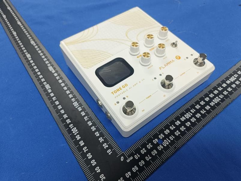
2BA4I-TONEGO
Aug 13, 2026INTELLIGENT AMP
Equipment Class
DSS - Part 15 Spread Spectrum Transmitter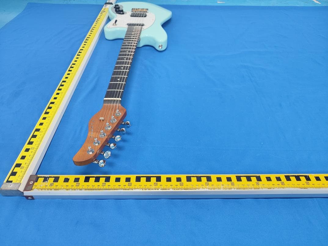
2BA4I-E1000
Mar 27, 2024Intelligent Guitar
Equipment Class
DTS - Digital Transmission System