2BD9Y-600PORTABLE POWER STATION
Senci Electro mechanical Co.Ltd.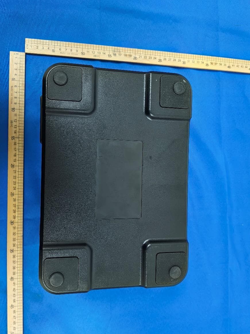
Click to zoom
Application Details
- Equipment Class
- DCD - Part 15 Low Power Transmitter Below 1705 kHz
- Date of Grant
- Jan 11, 2024
- Application Purpose
- Original Equipment
- Date of Application
- Jan 11, 2024
- Equipment Note
- PORTABLE POWER STATION
- Frequency Range
- 0.11000000 - 0.20500000
- Country
- China
Documents & Files
Document Text
Text extracted from the exhibit documents filed with the FCC. Open a document above to read the original.
Attestation Statements
Attestation Statements (2024/1/10) TO: Federal Communications Commission Authorization and Evaluation Division 7435 Oakland Mills Road Columbia, MD 21046, USA RE: Attestation Statements Part 2.911(d)(7) request for (GC: 2BD9Y) (Senci Electro mechanical Co.Ltd.), the undersigned, hereby authorize Wilson Tech Service LLC to act as our designated U.S. agent for service of process, (Senci Electro mechanical Co.Ltd.) accepts to maintain an agent for no less than one year after the grantee has terminated all marketing and importation or the conclusion of any Commission-related proceeding involving the equipment. Wilson Tech Service LLC accepts the responsibility to act as designated U.S. agent for service of process. Applicant Information: Company Name: Senci Electro mechanical Co.Ltd. Contact Name: Yong sheng Tang Address: No.200 Tongxinbei Road,Beibei District Chongqing 400701,China FRN: 0034656249 Telephone No: +86-023-88028731 Email: [email protected] Signature [ Yong sheng Tang] U.S. Agent Information: Company Name: Wilson Tech Service LLC Address: 1312 17th Street Suite 692, Denver, CO, 80202, US FRN: 0033402033 Contact Name: Wilson Cheung Telephone No: +1-716-965-5112 Email: [email protected] Signature [Wilson Cheung]
External Photos
External
ID Label/Location Info
99.00mm*59.00mm
Internal Photos
Internal
RF Exposure Info
1 / 9 EUT Specification FCC ID: 2BD9Y-600 Characteristics Description Product Name PORTABLE POWER STATION Model number Mid 600 Brand / Power Supply AC 120V/60Hz / DC 25V / Battery 25.6V Operating Frequency Range 110-205KHz for phone charging Modulation Technique FSK for phone charging Antenna Type Coil Antenna Device category Portable (<20cm separation) Mobile (>20cm separation) Others ___ Antenna diversity Single antenna Multiple antennas Tx diversity Rx diversity Tx/Rx diversity Evaluation applied MPE Evaluation SAR Evaluation Applicable Standard: FCC Part 1(1.1310) ,Part 2(2.1091) and KDB 680106 D01 RF Exposure Wireless Charging Apps v03 Applicable Requirement: Three different categories of transmitters are defined by the FCC in OET Bulletin 65. These categories are fixed installation, mobile, and portable and are defined as follows: 2 / 9 Fixed Installations: fixed location means that the device, including its antenna, is physically secured at a permanent location and is not able to be easily moved to another location. Additionally, distance to humans from the antenna is maintained to at least 2 meters. Mobile Devices: a mobile device is defined as a transmitting device designed to be used in other than fixed locations and to be generally used in such a way that a separation distance of at least 20 centimeters is normally maintained between the transmitter's radiating structures and the body of the user or nearby persons. Transmitters designed to be used by consumers or workers that can be easily re-located, such as a wireless modem operating in a laptop computer, are considered mobile devices if they meet the 20 centimeter separation requirement. The FCC rules for evaluating mobile devices for RF compliance are found in 47 CFR §2.1091. Portable Devices: a portable device is defined as a transmitting device designed to be used so that the radiating structure(s) of the device is/are within 20 centimeters of the body of the user. Portable device requirements are found in Section 2.1093 of the FCC's Rules (47 CFR§2.1093). The FCC also categorizes the use of the device as based upon the user’s awareness and ability to exercise control over his or her exposure. The two categories defined are Occupational/ Controlled Exposure and General Population/Uncontrolled Exposure. These two categories are defined as follows: Occupational/controlled exposure limits apply in situations in which persons are exposed as a consequence of their employment provided those persons are fully aware of the potential for exposure and can exercise control over their exposure. Limits for occupational/controlled exposure also apply in situations when a person is transient through a location where occupational/controlled limits apply provided he or she is made aware of the potential for exposure. The phrase fully aware in the context of applying these exposure limits means that an exposed person has received written and/or verbal information fully explaining the potential for RF exposure resulting from his or her employment. With the exception oftransient persons, this phrase also means that an exposed person has received appropriate training regarding work practices relating to controlling or mitigating his or her exposure. Such training is not required for transient persons, but they must receive written and/or verbal information and notification (for example, using signs) concerning their exposure potential and appropriate means available to mitigate their exposure. The phrase exercise control means that an exposed person is allowed to and knows how to reduce or avoid exposure by administrative or engineering controls and work practices, such as use of personal protective equipment or time averaging of exposure. General population/uncontrolled exposure limits apply in situations in which the general public may be exposed, or in which persons who are 3 / 9 exposed as a consequence of their employment may not be fully aware of the potential for exposure or cannot exercise control over their exposure. Licensees and applicants are responsible for compliance with both the occupational/controlled exposure limits and the general population/uncontrolled exposure limits as they apply to transmitters under their jurisdiction. Licensees and applicants should be aware that the occupational/controlled exposure limits apply especially in situations where workers may have access to areas in very close proximity to antennas and access to the general public may be restricted. In lieu of evaluation with the general population/uncontrolled exposure limits, amateur licensees authorized under part 97 of this chapter and members of his or her immediate household may be evaluated with respect to the occupational/controlled exposure limits in this section, provided appropriate training and information has been provided to the amateur licensee and members of his/her household. Other nearby persons who are not members of the amateur licensee's household must be evaluated with respect to the general population/uncontrolled exposure limits. Test Setup Block 4 / 9 Test Procedure 1.Connect the EUT and equipment as above diagram of test configuration. 2.EUT was placed on a table, and the measure probe was placed at a measurement distance of 15cm from the EUT to the center of the probe. 3.Power on the measuring probe, the EUT was set at the maximum field strength emission state. 4.The EUT was put in different directions (Left, Right, Front, Rear, Top and Bottom) toward to the measure probe. The distance from the top of the EUT to the probe is 20CM, and the distance from other directions is 15cm.Measure the value of field strength. 5.Record the worst data of the different directions. Measuring Device And Test Equipment Used Equipment Manufacturer Model No. Serial No. Last Cal. Due Date E&H-Field Probe(9kHz-30M Hz) Narda EHP-200A 180ZX11012 2023/09/18 2024/09/17 5 / 9 Description of Support Device Phone : Manufacturer: Apple Inc. M/N: A2176 S/N:…
Text truncated - open the document above for the full version.
Test Report
版权所有:重庆盟讯电子科技有限公司 SPECIFICATION 修订表Amendment list 编号 版本号 修订人 修订内容 日期 1 V1.3 Chen Canlun 2023/09/13 审批记录Approval record 版本号 审批人 审批意见 日期 V1.3 版权所有:重庆盟讯电子科技有限公司 2 MXC -A19Wireless charging module specification V1.3 Product functional specification definition Product functional specificati on definition Functional item Function description Structure and appearance appearance PCB size(mm) 60*60(mm) Configura tion and functions Supply voltage DC12V ±20% Power interface definition 2PIN Power interface definition: 1pin----GND; 2pin---- VCC , 12V; Wireless charging protocol Supports QC2.0/3.0 and PD3.0 input requests Supports Qi protocol BPP and PPDE authentication conforms to the WPC1.2.4 standard charging power 5W、7.5W、10W、15W Output application Foreign body detection ◆ Supports FOD foreign body detection ◆Foreign body size: 1 yuan coin is standard Low static power and efficiency Static current ≤25mA System charging efficiency > 79% (transmitting coil and receiving coil distance test 2mm) Safety Overcurrent protection during charging: 2.4A (During the charging process, abnormally large current occurs in the input of the charging chip, and the charge is interrupted). NTC overtemperature protection: > 75°C (broken charge) 版权所有:重庆盟讯电子科技有限公司 3 NTC overtemperature protection: 70-75°C (power reduction to 10W or less) NTC overtemperature protection recovery: < 70 °C NTC Low temperature protection: -10°C The power supply requires 12V±20%. The wireless charging module comes with a DCDC voltage regulator circuit and does not support over - and under-voltage protection. indicator light 1、Blue light: Power-on start, standby: breathing mode Charging, charging complete (full) : Steady on 2/ 2、Red Light: Input power low or overtemperature: Steady on 3、Overcurrent protection: the red light is on for 1s, and the blue light breathing is resumed Charging distance The best charging distance: The distance between the receiving coil of the charging device and the wireless charging module coil is 2-3mm (including the thickness of the housing).
Test Report
TRF No.: 04-E001-0B TRF Originator: GTG TRF Date: 2023-12-13 Web: www.gtggroup.com E-mail: [email protected] Tel.: 86-400 755 8988 ELECTROMAGNETIC EMISSIONS COMPLIANCE REPORT INTENTIONAL RADIATOR CERTIFICATION TO FCC PART 15 SUBPART C REQUIREMENT OF PORTABLE POWER STATION Model No.: Mid 600 FCC ID: 2BD9Y-600 Report No.: E04A23110605F00201 Issue Date: December 25, 2023 Prepared for Senci Electro mechanical Co.Ltd. No.200 Tongxinbei Road,Beibei District Chongqing 400701,China Prepared by Guangdong Global Testing Technology Co., Ltd. Room 101-105, 203-210, Building 1, No.2, Keji 8 Road, Songshan Lake Park, Dongguan city, Guangdong, People’s Republic of China, 523808 This report shall not be reproduced, except in full, without the written approval of Guangdong Global Testing Technology Co., Ltd. Page 1 of 42 Report No.: E04A23110605F00201 TRF No.: 04-E001-0B Global Testing , Great Quality. VERIFICATION OF COMPLIANCE Applicant: Senci Electro mechanical Co.Ltd. No.200 Tongxinbei Road,Beibei District Chongqing 400701,China Manufacturer: Senci Electro mechanical Co.Ltd. No.200 Tongxinbei Road,Beibei District Chongqing 400701,China Factory: Senci Electro mechanical Co.Ltd. No.200 Tongxinbei Road,Beibei District Chongqing 400701,China Product Description: PORTABLE POWER STATION Brand: / Model Number: Mid 600 We hereby certify that: The above equipment was tested by Guangdong Global Testing Technology Co., Ltd. The test data, data evaluation, test procedures, and equipment configurations shown in this report were made in accordance with the procedures given in ANSI C63.10-2013 and the energy emitted by the sample EUT tested as described in this report is in compliance with conducted and radiated emission limits of FCC Rules Part 15.209(2022). Date of Test : December 6, 2023 to December 20, 2023 Prepared by : Alan He/Editor Reviewer & Authorized Signer : Shawn Wen/ Laboratory Manager Page 2 of 42 Report No.: E04A23110605F00201 TRF No.: 04-E001-0B Global Testing , Great Quality. Modified Information Version Summary Revision Date Report No. Ver.1.0 Original Report / E04A23110605F00201 Page 3 of 42 Report No.: E04A23110605F00201 TRF No.: 04-E001-0B Global Testing , Great Quality. Table of Contents 1 GENERAL INFORMATION .................................................................................................................................. 4 1.1 PRODUCT DESCRIPTION .................................................................................................................................... 4 1.2 RELATED SUBMITTAL(S) / GRANT(S) ................................................................................................................. 5 1.3 TEST METHODOLOGY ........................................................................................................................................ 5 1.4 SPECIAL ACCESSORIES ..................................................................................................................................... 5 1.5 EQUIPMENT MODIFICATIONS ............................................................................................................................. 5 1.6 TEST FACILITY .................................................................................................................................................... 5 2 SYSTEM TEST CONFIGURATION ..................................................................................................................... 6 2.1 EUT CONFIGURATION ....................................................................................................................................... 6 2.2 EUT EXERCISE .................................................................................................................................................. 6 2.3 TEST PROCEDURE ............................................................................................................................................. 6 2.4 CONFIGURATION OF TESTED SYSTEM ............................................................................................................... 7 3 SUMMARY OF TEST RESULTS ......................................................................................................................... 7 4 TEST SYSTEM UNCERTAINTY .......................................................................................................................... 8 5 CONDUCTED EMISSIONS TEST ....................................................................................................................... 9 5.1 MEASUREMENT PROCEDURE ............................................................................................................................ 9 5.2 TEST SET-UP (BLOCK DIAGRAM OF CONFIGURATION) ................................................................................... 9 5.3 MEASUREMENT EQUIPMENT USED .................................................................................................................... 9 5.4 CONDUCTED EMISSION LIMIT ............................................................................................................................ 9 5.5 MEASUREMENT RESULT .................................................................................................................................. 10 5.6 CONDUCTED MEASUREMENT PHOTO .............................................................................................................. 13 6 RADIATED EMISSION TEST............................................................................................................................. 14 6.1 MEASUREMENT PROCEDURE .......................................................................................................................... 14 6.2 TEST SET-UP (BLOCK DIAGRAM OF CONFIGURATION) ................................................................................. 14 6.3 MEASUREMENT EQUIPMENT USED ................................................................…
Text truncated - open the document above for the full version.
Test Setup Photos
Conducted Measurement Photo Radiated Measurement Photos 9kHz-30MHz 30MHz-1GHz
Contact Information
Applicant
Yong sheng Tang(Manager)
Technical Contact
Guangdong Global Testing Technology Co., Ltd.Shawn Wen
[email protected]86 769 8507 5888
Room 101-105,203-210, Building 1, No.2, Keji 8 · Dongguan · China
Non-Technical Contact
Guangdong Global Testing Technology Co., Ltd.Shawn Wen
[email protected]86 769 8507 5888
Test Firm
Guangdong Global Testing Technology Co., Ltd.Shawn Wen
[email protected]86 769 8507 5888
Technical Specifications
| # | Rule Parts | Frequency Range | Power Output |
|---|---|---|---|
| 1 | 15C | 0.11 MHz - 0.205 MHz | - |
Other Applications from Senci Electro mechanical Co.Ltd.
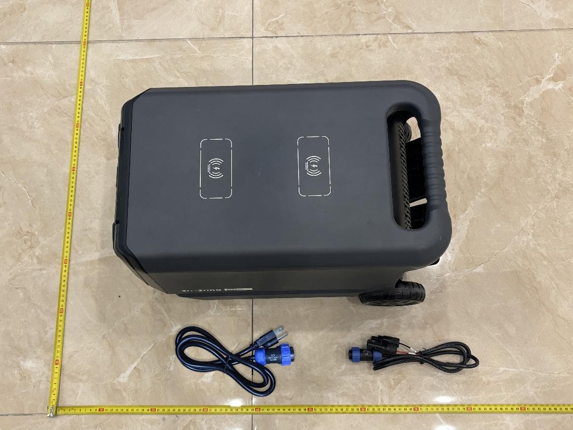
2BD9Y-SC2000
Feb 25, 2026Portable Power Station
Equipment Class
DCD - Part 15 Low Power Transmitter Below 1705 kHz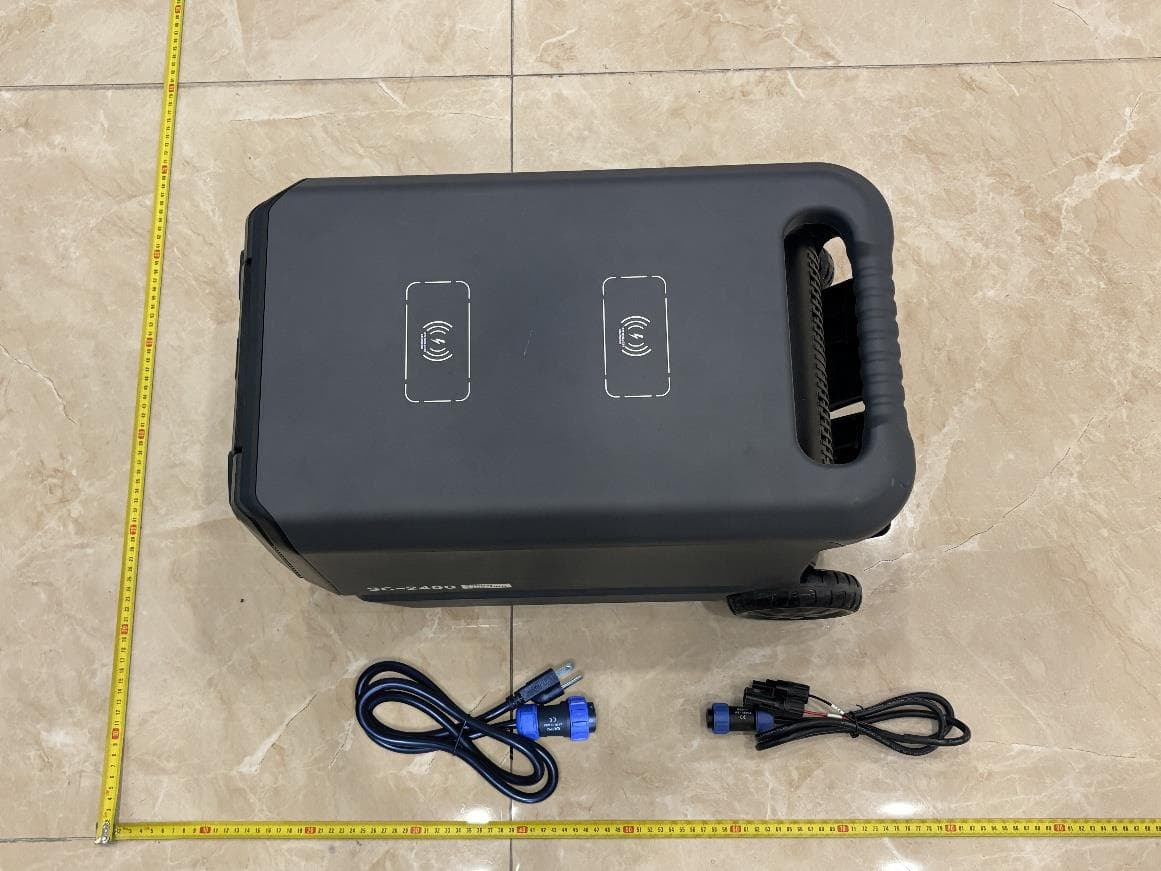
2BD9Y-SC2400
Feb 25, 2026Portable Power Station
Equipment Class
DCD - Part 15 Low Power Transmitter Below 1705 kHz