2BDTF-ELRFLaser Range Finder
STEINER-Optik GmbH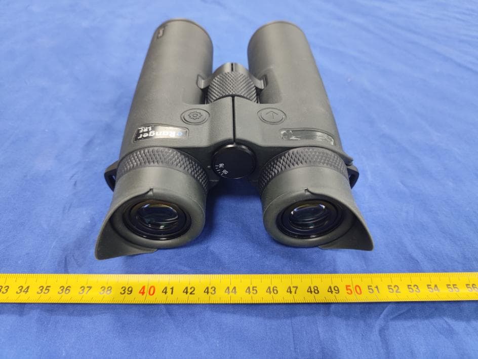
Click to zoom
Application Details
- Equipment Class
- DTS - Digital Transmission System
- Date of Grant
- Jun 27, 2024
- Application Purpose
- Original Equipment
- Date of Application
- Jun 27, 2024
- Equipment Note
- Laser Range Finder
- Frequency Range
- 2402.00000000 - 2480.00000000
- Company
- STEINER-Optik GmbH
- Country
- Germany
Documents & Files
Document Text
Text extracted from the exhibit documents filed with the FCC. Open a document above to read the original.
Users Manual
Operating instructions 3 We congratulate you on purchasing these STEINER binoculars! Look forward to great moments. The accessories included in the scope of delivery can be used according to your wishes. Proper handling is the prerequisite for decades of enjoyment with this precision device. Please read the following pages before using it for the first time. EN 4 5 CONTENT Operating instructions: Steiner Connect App 2.0 ................................................................................................................................. 5 Presentation of the product components ......................................................................................................... 6 Main menu Overview ....................................................................................................................................... 7 Battery ............................................................................................................................................................. 8 Laser distance measurements ........................................................................................................................ 9 Menu overview............................................................................................................................................... 10 Important information ..................................................................................................................................... 13 Disposal of electrical and electronic devices ................................................................................................. 14 STEINER CONNECT APP 2.0 With the Steiner Connect App 2.0 you can manage settings and use the Impact Locator, which supports you in your search. To do this, connect your eRanger LRF to the Steiner Connect App 2.0 and follow the instructions in the app. Once your eRanger LRF is successfully connected to the app, the settings can be adjusted to suit your needs. The Impact Locator (search function) is activated in the Steiner Connect App 2.0 by clicking on one of the last 3 measurements. This will automatically open Google ® maps and you can navigate to one of these measuring points. You can find further explanatory videos on our YouTube channel “Steiner-Optik.” STEINER CONNECT APP 2.0 EN 6 7 PRESENTATION OF THE PRODUCT COMPONENTS Illustration 1: Target mark Distance display Unit of measurement Feature modes Units of measurement angle / compass / Horizontal distance Distance display angle or compass Compass icon Angle icon Battery status indicator Active Bluetooth ® connection MAIN MENU OVERVIEW Symbols in Figure 2. Eyepiece with twist-up eyecups Power/measurement/scan button Menu button Battery compartment Focus wheel Diopter compensation Fig. 2 EN 8 9 BATTERY LASER RANGEFINDER Inserting and replacing the battery: The laser rangefinder is powered by a CR 2 battery. To insert and replace the battery, unscrew the battery compartment D by turning it counterclockwise. Insert the battery with its positive contact first (according to the symbols in the battery compartment). Then screw the battery compartment tight again by turning it clockwise. To unscrew the battery compartment, use the Steiner tool included in the delivery. Battery charge level: A new battery is enough for more than 2500 measurements at the optimal temperature. Battery life can be significantly shorter or longer depending on the application conditions . Low temperatures and frequent use of the scan mode shorten battery life. If a battery symbol " " is displayed at the top of the field of view during operation in one of the modes, it means that the battery needs to be changed. Attention: Cold reduces battery life. At low temperatures, the LRF should therefore be worn as close to the body as possible and used with a new/as-new battery. These are carried out using an eye-safe, invisible laser pulse. The eRanger LRF can display the measured distance in meters or yards. When measuring, either “M” for meters or “Y” for yards is displayed next to the respective distance display. You can change the setting using the menu button in the menu: If you press the button for a longer period of time (> 3 seconds), the menu opens in which you can change the measuring unit of the respective distance display. For further information, please see the menu overview on page 12. EN C 10 11 MENU OVERVIEW Standard mode: No additional icons appear and you are not in any special mode. The distance can be measured or the scan mode can be activated. Display brightness: The brightness of the displays can be set in 6 different levels by pressing the " " button. Accessing your saved measurements display: You can view the last three measurements from the eRanger LRF's internal memory and switch between them. This feature allows you to quickly and easily retrieve previous measurement results. Line of sight + ANGLE - ANGLE Horizontal distance "HD" Horizontal distance "HD" Your position Line of sight Distance display angle / compass or horizontal distance: The display can be selected between angle (degrees), angle (meters) – in this setting the horizontal distance is displayed – and compass (degrees). Customization of feature modes: Priority of a closer object If more than one target object is detected by the eRanger LRF, the distance of the closer object is shown on the display. EN Priority of another object This mode ignores objects, e.g. bushes, stones and branches, in the foreground. If more than one target object is detected by the eRanger LRF, the distance of the more distant object is shown on the display. Allows measurement in extreme weather conditions, such as heavy rain. Switching the Bluetooth ® connection on/off: You can turn the Bluetooth ® connection on or off depending on your needs. Activate Bluetooth ® to be able to connect to the eRanger 8 or the Steiner Connect App 2.0. Setting or selecting the scale unit or unit of measurement: Yo…
Text truncated - open the document above for the full version.
External Photos
Bay Area Compliance Laboratories Corp. (Chengdu) Project No.: RSC240304002 Page 1 of 4 EXHIBIT B – EUT EXTERNAL PHOTOGRAPHS Top View Bottom View Bay Area Compliance Laboratories Corp. (Chengdu) Project No.: RSC240304002 Page 2 of 4 Side 1 View Side 2 View Bay Area Compliance Laboratories Corp. (Chengdu) Project No.: RSC240304002 Page 3 of 4 Side 3 View Bay Area Compliance Laboratories Corp. (Chengdu) Project No.: RSC240304002 Page 4 of 4 Side 4 View
ID Label/Location Info
Bay Area Compliance Laboratories Corp. (Chengdu) Project No.: RSC240304002 EXHIBIT A -LABELING AND LOCATION Label Label Location
Internal Photos
Bay Area Compliance Laboratories Corp. (Chengdu) Project No.: RSC240304002 Page 1 of 10 EXHIBIT C – EUT INTERNAL PHOTOGRAPHS EUT – Uncovered View Bay Area Compliance Laboratories Corp. (Chengdu) Project No.: RSC240304002 Page 2 of 10 Bay Area Compliance Laboratories Corp. (Chengdu) Project No.: RSC240304002 Page 3 of 10 EUT – PCB View BLE Antenna BLE Module Bay Area Compliance Laboratories Corp. (Chengdu) Project No.: RSC240304002 Page 4 of 10 Bay Area Compliance Laboratories Corp. (Chengdu) Project No.: RSC240304002 Page 5 of 10 Bay Area Compliance Laboratories Corp. (Chengdu) Project No.: RSC240304002 Page 6 of 10 Bay Area Compliance Laboratories Corp. (Chengdu) Project No.: RSC240304002 Page 7 of 10 Bay Area Compliance Laboratories Corp. (Chengdu) Project No.: RSC240304002 Page 8 of 10 Bay Area Compliance Laboratories Corp. (Chengdu) Project No.: RSC240304002 Page 9 of 10 BLE Module View Bay Area Compliance Laboratories Corp. (Chengdu) Project No.: RSC240304002 Page 10 of 10 EUT – Battery View
RF Exposure Info
Bay Area Compliance Laboratories Corp. (Chengdu) Report Number: RSC240304002-0B Version 1.0 (2023-11-07) Page 12 of 49 QB-Report-EM-7.8-0-001 FCC §15.247 & §1.1310 & §2.1093 - RF EXPOSURE Applicable Standard According to§15.247(i) and §1.1310, systems operating under the provisions of this section shall be operated in a manner that ensure that the public is not exposed to radio frequency energy level in excess of the Commission’s guideline. According to KDB447498 D01 General RF Exposure Guidance v06: The 1-g and 10-g SAR test exclusion thresholds for 100 MHz to 6 GHz at test separation distances ≤ 50 mm are determined by: [(max. power of channel, including tune-up tolerance, mW)/(min. test separation distance, mm)] . [√f(GHz)] ≤ 3.0 for 1-g SAR and ≤ 7.5 for 10-g extremity SAR, where • f(GHz) is the RF channel transmit frequency in GHz • Power and distance are rounded to the nearest mW and mm before calculation • The result is rounded to one decimal place for comparison • 3.0 and 7.5 are referred to as the numeric thresholds in the step 2 below The test exclusions are applicable only when the minimum test separation distance is ≤ 50 mm and for transmission frequencies between 100 MHz and 6 GHz. When the minimum test separation distance is < 5 mm, a distance of 5 mm according to 5) in section 4.1 is applied to determine SAR test exclusion. Measurement Result The max conducted power including tune-up tolerance is 5.0 dBm (3.16mW). [(max. power of channel, mW)/(min. test separation distance, mm)][√f(GHz)] = 3.16/5*(√2.48) = 1.0< 3.0 So the stand-alone SAR evaluation is not necessary.
Test Report
Te s t Engineer:yin Report date: 2017.11.25 Antenna Measurement Report CONTENTS Project Overview 1 Passive Report 3 Test Environment 2 Project Overview 3 PART WO Measuring frequency:2.4-2.5GHZ PCB version:HY-40R204P Test Environment 4 最近工作和生活都有 些懈怠,事情比较多 比较杂,搅在一起让 人丧失了动力 PART WO 看完了关于如何做科 学研究的几本书,只 是觉得像喝了几碗鸡 汤,然并卵罢了 (ETS) and (MVG SG24LT(Satmio)) Laboratory System Passive Report 5 Directivity Measured Data Measuring Instrument:Agilent Technologies E5071B 300kHz-8.5GHz ENA Series Network Analyzer Laboratory System:MVG SG24LT(Satmio) Passive Report 6 PART WO Directivity Measured Data Measuring Instrument:Agilent Technologies E5071B 300kHz-8.5GHz ENA Series Network Analyzer Laboratory System:MVG SG24LT(Satmio) Passive Report 7 PART WO Directivity Measured Data Measuring Instrument:Agilent Technologies E5071B 300kHz-8.5GHz ENA Series Network Analyzer Laboratory System:MVG SG24LT(Satmio) Passive Report 8 PART WO Directivity Measured Data Measuring Instrument:Agilent Technologies E5071B 300kHz-8.5GHz ENA Series Network Analyzer Laboratory System:MVG SG24LT(Satmio) Passive Report 9 Directivity Measured Data Measuring Instrument:Agilent Technologies E5071B 300kHz-8.5GHz ENA Series Network Analyzer Laboratory System:MVG SG24LT(Satmio)
Test Report
Note: BACL is not responsible for the authenticity of any test data or information provided by the applicant. Test data or information included from the applicant that may affect test results are marked with an asterisk ‘*’. Do not include customer model name, addresses, names and trademarks. This report cannot be reproduced except in full, without prior written approval of the company. This report may contain data that are not covered by the NVLAP accreditation scope and shall be marked with an asterisk “ ◇ ” The report must not be used by the client to claim product certification, approval, or endorsement by NVLAP, NIST, or any agency of the U.S. Government. Version 1.0 (2023-11-07) Page 1 of 49 QB-Report-EM-7.8-0-001 FCC PART 15.247 TEST REPORT For STEINER-Optik GmbH Dr.-Hans-Frisch-Str. 9 95448 Bayreuth Germany Re p o r t T yp e : O r ig in a l Re p o r t Pr o d u c t Na m e: L a s e r R a n g e F i n d e r Report Number: RSC240304002-0B Date of Report Issue: 2024-04-19 Reviewed By: Sula Huang Test Laboratory: Bay Area Compliance Laboratories Corp. (Chengdu) No.5040, Huilongwan Plaza, No. 1, Shawan Road, Jinniu District, Chengdu, Sichuan, China Tel: +86-28-65525123 Fax: +86-28-65525125 www.baclcorp.com Tested Model: eRanger LRF 10x42 FCC ID: 2BDTF-ELRF Bay Area Compliance Laboratories Corp. (Chengdu) Report Number: RSC240304002-0B Version 1.0 (2023-11-07) Page 2 of 49 QB-Report-EM-7.8-0-001 TABLE OF CONTENTS GENERAL INFORMATION ........................................................................................................................................ 3 PRODUCT DESCRIPTION FOR EQUIPMENT UNDER TEST (EUT) ................................................................................ 3 OBJECTIVE .................................................................................................................................................................. 3 MEASUREMENT UNCERTAINTY ................................................................................................................................... 4 TEST METHODOLOGY ................................................................................................................................................. 4 TEST FACILITY ............................................................................................................................................................. 4 SYSTEM TEST CONFIGURATION ........................................................................................................................... 5 DESCRIPTION OF TEST CONFIGURATION* .................................................................................................................. 5 EQUIPMENT MODIFICATIONS ...................................................................................................................................... 5 EUT EXERCISE SOFTWARE* ...................................................................................................................................... 5 SUPPORT TEST DEVICES DESCRIPTION ..................................................................................................................... 7 SUPPORT TEST CABLE DESCRIPTION ........................................................................................................................ 7 BLOCK DIAGRAM OF TEST SETUP .............................................................................................................................. 7 SUMMARY OF TEST RESULTS ............................................................................................................................... 9 TEST EQUIPMENTS LIST ........................................................................................................................................ 10 FCC §15.247 & §1.1310 & §2.1093 - RF EXPOSURE......................................................................................... 12 APPLICABLE STANDARD ............................................................................................................................................ 12 FCC §15.203 - ANTENNA REQUIREMENT .......................................................................................................... 13 APPLICABLE STANDARD ............................................................................................................................................ 13 ANTENNA INFORMATION* .......................................................................................................................................... 13 FCC §15.209, §15.205 & §15.247(d) - RADIATED SPURIOUS EMISSIONS & BAND EDGE .................... 14 APPLICABLE STANDARD ............................................................................................................................................ 14 EUT SETUP ............................................................................................................................................................... 14 EMI TEST RECEIVER & SPECTRUM ANALYZER SETUP ........................................................................................... 15 TEST PROCEDURE .................................................................................................................................................... 16 CORRECTED AMPLITUDE & MARGIN CALCULATION ................................................................................................. 16 CONDUCTED SPURIOUS EMISSION AT ANTENNA PORT: ......................................................................................... 16 TEST SETUP BLOCK .................................................................................................................................................. 17 TEST DATA ................................................................................................................................................................ 17 FCC §15.247(a) (2) – 6 dB EMISSION BANDWIDTH .............…
Text truncated - open the document above for the full version.
Test Setup Photos
Bay Area Compliance Laboratories Corp. (Chengdu) Report No.: RSC240304002-0B Page 1 of 2 EXHIBIT D - TEST SETUP PHOTOGRAPHS Radiated Emission View (9kHz-30MHz) Radiated Emission View (30MHz-1GHz) Bay Area Compliance Laboratories Corp. (Chengdu) Project No.: RSC240304002 Page 2 of 2 Radiated Emission Front View (1GHz-18GHz) Radiated Emission Front View (18GHz-26.5GHz)
Contact Information
Applicant
Andreas Ruf(Leader of Quality Assurance)
Test Firm
Bay Area Compliance Laboratories Corp. (Chengdu)May Chen
[email protected]86-028-65525123
Technical Specifications
| # | Rule Parts | Frequency Range | Power Output |
|---|---|---|---|
| 1 | 15C | 2.40 GHz - 2.48 GHz | 2.70 mW |
Other Applications from STEINER-Optik GmbH
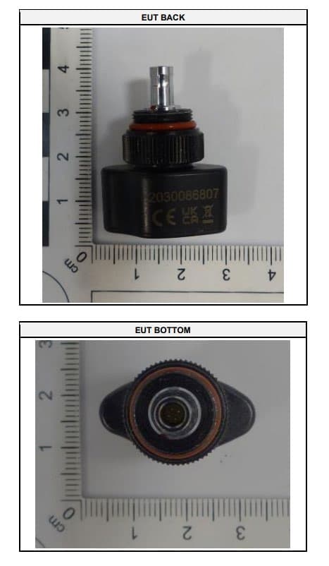
2BDTF-LRFTRX
Jul 11, 2024Bluetooth Transceiver for Laser Range Finding Binoculars
Equipment Class
DTS - Digital Transmission System