2BDWS-RU471BUHF RFID Fixed Reader
SHENZHEN SYSIOT CO., LTD.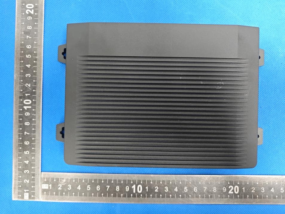
Click to zoom
Application Details
- Equipment Class
- DSS - Part 15 Spread Spectrum Transmitter
- Date of Grant
- Sep 01, 2024
- Application Purpose
- Original Equipment
- Date of Application
- Sep 01, 2024
- Equipment Note
- UHF RFID Fixed Reader
- Frequency Range
- 902.75000000 - 927.25000000
- Company
- SHENZHEN SYSIOT CO., LTD.
- Country
- China
Documents & Files
Document Text
Text extracted from the exhibit documents filed with the FCC. Open a document above to read the original.
Users Manual
1 / 3 UHF RFID Fixed Reader Model: SR-RU471B SR-RU471B General Description The SR-RU471B is an ultra-high-performance UHF RFID fixed reader that combines a proprietary and efficient collision processing algorithm to achieve rapid reading of electronic tags while maintaining a high reading rate. Write processing has the characteristics of long reading distance, fast recognition speed, various interface types, small size and easy installation. It can be widely used in various applications such as logistics tracking, commodity inventory, cargo sorting, vehicle management, personnel management, asset management, medical systems, cold chain management, temperature monitoring, power monitoring, anti-counterfeiting systems and production process control. Features *Based on IMPINJ E710 chip design, fully supports EPC C1G2 (ISO18000-6C) protocol *Support EU 840~868MHz, US 902~928MHz working frequency (or Customized) *Optimized multi-label inventory algorithm, the peak tags inventory speed reaches 1,000 /second *Works in broad spectrum frequency hopping (FHSS) *Tag buffer area 1000 tags @ 96bit EPC *Support command, polling, and trigger mode *Supports independent and combined inventory of EPC, TID, and USER data areas *Low power dissipation with single +12 DC power supply *Interface support USB, RS232, RS485, Weigand, RJ45(TCP/IP, UDP) *Support 4 antenna SMA port *Number of tag caches up to 800pcs (96-bit EPC length) *Provide DEMO and SDK for development *Support development based on Windows, Android, Linux etc. and C, C#, JAVA, Python etc. 2 / 3 Specification Main Function Protocol EPC Global UHF Class 1 Gen 2 / ISO 18000-6C RSSI Support RFID Parameter Frequency 902-928MHz at option; FHSS Tag Reading Reading distance ≥45m Writing distance ≥10m Multiple tag reading speed ≥1,000pcs/s Communication Parameter Interface USB, RS232, RS485/Weigand, RJ45(TCP/IP, UDP) 4 GPIO, including 2 GPI and 2 GPO Baud rate 115200bps Power Parameter Operating Voltage DC 12.0V (9V~24V) Operating Current ≤600mA / DC 12V Standby Current ≤100mA / DC 12V PoE Support, at option Working Environment Operating Temperature -20~+55°C Storage Temperature -30~+85°C Operating Humidity <95%RH (+25°C) Non-condensing 3 / 3 Dimension FCC WARNING This device complies with part 15 of the FCC Rules. Operation is subject to the follow ing two conditions : (1) this device may not cause harmful interference, and (2) this device must accept any interference received, inc luding interference that may cause undesired operation. Any changes or modifications not expressly approved by the party responsible for compliance could void the user's authority to operate the equipment. NOTE: This equipment has been tested and found to comply with the limits for a Class B digital device, pursuant to Part 15 of the FCC Rules. These limits are designed to provide reasonable protection against harmful interference in a residentia l installation. This equipment generates, uses and can radiate radio frequency energy and, if not installed and used in accordance with the instructions, may cause harmful interference to radio communications. However, there is no guarantee that interference will not occur in a particular installation. If this equipment does cause harmful interference to radio or televis ion reception, which can be determined by turning the equipment off and on, the user is encouraged to try to correct the interference by one or more of the following measures: -- Reorient or relocate the receiving antenna. -- Increase the separation between the equipment and receiver. -- Connect the equipment into an outlet on a circuit different from that to which the receiver is connected. -- Consult the dealer or an experienced radio/TV technic ian for help. To maintain compliance with FCC’s RF Exposure guidelines, This equipment should be insta lled and operated with minimum distance between 20cm the radiator your body: Use only the supplied antenna.
Attestation Statements
SHENZHEN SYSIOT CO., LTD. U.S. Agent Designation for Service of Process (Applicant and U.S. Agent are Separate Parties) TO: Federal Communications Commission Authorization and Evaluation Division 7435 Oakland Mills Road Columbia, MD 21046, USA ATTENTION: FCC Certification – Section 2.911(d)(7) Information Designated U.S. Agent Company Name: AOCE Corporation Inc. FRN: 0033401381 Contact Name: Johnson.wang Address: 6547 N Academy Bivd #2266, Colorado Springs, CO,80918 United States Telephone No: +1-346-582-5234 Email: [email protected] This letter is to confirm that we (AOCE Corporation Inc.) have accepted the responsibility to act as the Designated U.S. Agent for Service of Process as required by section 47 CFR 2.911(d)(7) on behalf of the Applicant noted below. U.S. Agent Signature: Date: 2024-08-15 Signed by (Printed Name/Title): The Applicant acknowledges that they must maintain an agent for no less than one year after terminating all marketing and importation OR the conclusion of any Commission-related proceeding involving the equipment. The applicant further acknowledges their responsibility to inform the FCC whenever the Designated U.S. Agent information above changes. Applicant Company name: SHENZHEN SYSIOT CO., LTD. FRN: 0034573758 FCC ID: 2BDWS-RU471B Contact Name: Kelly Lu Address: Room 263, Yiben E-Commerce and Industrial Park, Chaguang Road, Nanshan District, Shenzhen, China Telephone No: 13510109936 Email: [email protected] Applicant Signature: Date: 2024-08-15 Signed by (Printed Name/Title): Kelly Lu / Manager
Attestation Statements
SHENZHEN SYSIOT CO., LTD. 2024.08.26 Eurofins Electrical and Electronic Testing NA, Inc. 914 West Patapsco Avenue Baltimore, MD 21230 RE: Attestation Statements Part 2.911(d)(5)(i) request for FCC ID: 2BDWS-RU471B [SHENZHEN SYSIOT CO., LTD.] (“the applicant”) certifies that the equipment for which authorization is sought is not “covered” equipment prohibited from receiving an equipment authorization pursuant to section 2.903 of the FCC rules. Sincerely, (Applicant signature) (Applicant printed name) Kelly Lu SHENZHEN SYSIOT CO., LTD. 2024.08.26 Eurofins Electrical and Electronic Testing NA, Inc. 914 West Patapsco Avenue Baltimore, MD 21230 RE: Attestation Statements Part 2.911(d)(5)(ii) request for FCC ID: 2BDWS-RU471B [SHENZHEN SYSIOT CO., LTD.] (“the applicant”) certifies that, as of the date of the filing of the application, the applicant is not identified on the Covered List as an entity producing “covered” equipment. Sincerely, (Applicant signature) (Applicant printed name) Kelly Lu
Cover Letter(s)
SHENZHEN SYSIOT CO., LTD. 2024.08.26 Eurofins Electrical and Electronic Testing NA, Inc. 914 W. Patapsco Avenue Baltimore, MD 21230 USA RE: CONFIDENTIALITY REQUEST FOR EUT NAME: UHF RFID Fixed Reader Trademark: SysIoT MODEL : SR-RU471B, SR-RU471C, SR-RU471D FCC ID : 2BDWS-RU471B To Whom It May Concern: This letter serves as an official request for confidentiality under sections 0.457 and 0.459 of CFR 47. We have requested that the - Block Diagram - Schematics - Operational Description required to be submitted with this application be permanently withheld from public review. The above materials contain trade secrets and proprietary information not customarily released to the public. The public disclosure of these materials may be harmful to the applicant and provide unjustified benefits to its competitors. Please contact me if there is any information you may need. Sincerely, Client’s signature: Client’s name / title : Kelly Lu / Manager Contact information / address: Room 263, Yiben E-Commerce and Industrial Park, Chaguang Road, Nanshan District, Shenzhen, China
Cover Letter(s)
SHENZHEN SYSIOT CO., LTD. 2024.08.26 Eurofins Electrical and Electronic Testing NA, Inc. 914 W. Patapsco Avenue Baltimore, MD 21230 USA RE: LETTER OF AGENT AUTHORIZATION To Whom It May Concern: We, the undersigned, hereby authorize Shenzhen BCTC Testing Co., Ltd to act on our behalf in all matters relating to application for equipment authorization, including the signing of all documents relating to these matters. We also hereby certify that no party to the application authorized hereunder is subject to the denial of benefits, including FCC benefits, pursuant to Section 5301 of the Anti-Drug Abuse Act of 1988, 21 U.S.C.853(a). This agreement expires one year from the current date. Sincerely, Client’s signature: Client’s name / title : Kelly Lu / Manager Contact information / address: Room 263, Yiben E-Commerce and Industrial Park, Chaguang Road, Nanshan District, Shenzhen, China
Cover Letter(s)
SHENZHEN SYSIOT CO., LTD. Model Difference 2024-08-26 EUT NAME: UHF RFID Fixed Reader FCC ID: 2BDWS-RU471B MODEL : SR-RU471B, SR-RU471C, SR-RU471D All the model are the same circuit and RF module, except model names and appearance of the color.. Regards Sincerely Client’s signature: Client’s name / title : Kelly Lu / Manager Contact information / address: Room 263, Yiben E-Commerce and Industrial Park, Chaguang Road, Nanshan District, Shenzhen, China
External Photos
Report No.: BCTC2407889263E External Photos Antenna Report No.: BCTC2407889263E Report No.: BCTC2407889263E Report No.: BCTC2407889263E Report No.: BCTC2407889263E
ID Label/Location Info
Size:40*20mm UHF RFID Fixed Reader FCC ID: 2BDWS-RU471B This device complies with part 15 of the FCC Rules. Operation is subject to the following two conditions: (1) This device may not cause harmful interference, and (2) this device must accept any interference received, including interference that may cause undesired operation. Label location
Internal Photos
Report No.: BCTC2407889263E Internal Photos Report No.: BCTC2407889263E Report No.: BCTC2407889263E Report No.: BCTC2407889263E
RF Exposure Info
FCC §15.247 (i), §2.1091 – RF Exposure FCC ID: 2BDWS-RU471B Applied procedures / limit According to FCC §15.247(i) and §1.1307(b)(1), systems operating under the provisions of this section shall be operated in a manner that ensures that the public is not exposed to radio frequency energy level in excess of the Commission’s guidelines. Limits for Occupational / Controlled Exposure Frequency Range (MHz) Electric Field Strength (E) (V/m) Magnetic Field Strength (H) (A/m) Power Density (S) (mW/ cm 2 ) Averaging Time |E| 2 ,|H| 2 or S (minutes) 0.3-3.0 614 1.63 (100)* 6 3.0-30 1842 / f 4.89 / f (900 / f)* 6 30-300 61.4 0.163 1.0 6 300-1500 F/300 6 1500-100,000 5 6 Note: ƒ is frequency in MHz * = Power density limit is applicable at frequencies greater than 100 MHz Limits for General Population / Uncontrolled Exposure Frequency Range (MHz) Electric Field Strength (E) (V/m) Magnetic Field Strength (H) (A/m) Power Density (S) (mW/ cm 2 ) Averaging Time |E| 2 ,|H| 2 or S (minutes) 0.3-1.34 614 1.63 (100)* 30 1.34-30 824/f 2.19/f (180/f)* 30 30-300 27.5 0.073 0.2 30 300-1500 F/1500 30 1500-100,000 1.0 30 Note: f = frequency in MHz * = Plane-wave equivalent power density MPE PREDICTION Predication of MPE limit at a given distance, Equation from OET Bulletin 65, Edition 97-01 Where: S = power density P = power input to antenna G = power gain of the antenna in the direction of interest relative to an isotropic radiator R = distance to the center of radiation of the antenna, R=0.2m TEST RESULTS Conclusion: For the max result: 0.00502≤ 0.6, compliance with FCC's RF Exposure Tune up Produce power Maximu m peak output power (dBm) Output power to antenn a (mW) Antenna Gain (numeric) Power Density (S) (mW/ cm2) Limit (mW / cm2 ) Result RF ID 27±1 28 630.96 0.04 (-14.54dBi) 0.00502 0.6 Pass
Test Report
1 / 5 UHF near-field antenna Model:RR-UANT-0606NF Size:62mmx62mmx6mm Weight:100g SHENZHEN SYSIOT CO., LTD. Address: Room 263, Yiben E-Commerce and Industrial Park, Chaguang Road, Nanshan District, Shenzhen, China Introduction RR-UANT-0606NF is a high-performance UHF ultra-high frequency circularly polarized near-field antenna. Can be widely used in tag inventory, verification and other processes; In addition, it is widely used in library applications and the new retail industry, such as automatic book borrowing and returning systems, unmanned retail stores, and various wireless radio frequency identification (RFID) systems. 2 / 5 Mechanical drawings: Unit: mm Parameter: Item Symbol Numerical value Unit Working Temperature T OPR -20~+55°C Storage temperature T STR -40~+70°C Specification: Item Describe Frequency 902-928MHz Gain -14.54 dBi Type of connector RP-SMA Voltage standing wave ratio ≤1.5 Magnetic Field Intensity 0.1A/m (5cm above the antenna) Impedance 50 Ω Antenna cover material PCB Color Black 3 / 5 Polarization direction Circular polarization Lightning Protection DC to ground 4 / 5 5 / 5
Test Report
No.:BCTC/RF-EMC-005 Page: 1 of 70 Edition:B.2 TEST REPORT Shenzhen BCTC Testing Co., Ltd. Report No.: BCTC2407889263E Applicant: SHENZHEN SYSIOT CO., LTD. Product Name: UHF RFID Fixed Reader Test Model: SR-RU471B Tested Date: 2024-07-22 to 2024-08-12 Issued Date: 2024-08-12 Report No.: BCTC2407889263E No.:BCTC/RF-EMC-005 Page: 2 of 70 Edition:B.2 FCC ID: 2BDWS-RU471B The test report is effective only with both signature and specialized stamp. This result(s) shown in this report refer only to the sample(s) tested. Without written approval of Shenzhen BCTC Testing Co., Ltd, this report can’t be reproduced except in full. The tested sample(s) and the sample information are provided by the client. Product Name: UHF RFID Fixed Reader Trademark: SysIoT Model/Type Reference: SR-RU471B SR-RU471C, SR-RU471D Prepared For: SHENZHEN SYSIOT CO., LTD. Address: Room 263, Yiben E-Commerce and Industrial Park, Chaguang Road, Nanshan District, Shenzhen, China Manufacturer: SHENZHEN SYSIOT CO., LTD. Address: Room 263, Yiben E-Commerce and Industrial Park, Chaguang Road, Nanshan District, Shenzhen, China Prepared By: Shenzhen BCTC Testing Co., Ltd. Address: 1-2/F., Building B, Pengzhou Industrial Park, No.158, Fuyuan 1st Road, Zhancheng, Fuhai Subdistrict, Bao'an District, Shenzhen, Guangdong, China Sample Received Date: 2024-07-22 Sample tested Date: 2024-07-22 to 2024-08-12 Issue Date: 2024-08-12 Report No.: BCTC2407889263E Test Standards FCC CFR Title 47 Part 15 Subpart C Section 15.247 FCC KDB 558074 D01 15.247 Meas Guidance v05r02 ANSI C63.10:2013 Test Results PASS Tested by: Approved by: Lei Chen/Project Handler Zero Zhou/Reviewer Report No.: BCTC2407889263E No.:BCTC/RF-EMC-005 Page: 3 of 70 Edition:B.2 Table Of Content Test Report Declaration Page 1. Version .................................................................................................................. 5 2. Test Summary ....................................................................................................... 6 3. Measurement Uncertainty ..................................................................................... 7 4. Product Information And Test Setup ..................................................................... 8 4.1 Product Information ............................................................................................... 8 4.2 Test Setup Configuration ...................................................................................... 8 4.3 Support Equipment ............................................................................................... 9 4.4 Channel List .......................................................................................................... 9 4.5 Test Mode ........................................................................................................... 10 4.6 Table Of Parameters Of Text Software Setting ................................................... 10 5. Test Facility And Test Instrument Used ............................................................... 11 5.1 Test Facility ......................................................................................................... 11 5.2 Test Instrument Used .......................................................................................... 11 6. Conducted Emissions .......................................................................................... 13 6.1 Block Diagram Of Test Setup .............................................................................. 13 6.2 Limit .................................................................................................................... 13 6.3 Test procedure .................................................................................................... 13 6.4 EUT operating Conditions ................................................................................... 13 6.5 Test Result .......................................................................................................... 14 7. Radiated Emissions ............................................................................................. 16 7.1 Block Diagram Of Test Setup .............................................................................. 16 7.2 Limit .................................................................................................................... 17 7.3 Test procedure .................................................................................................... 18 7.4 EUT operating Conditions ................................................................................... 19 7.5 Test Result .......................................................................................................... 19 8. Radiated Band Emission Measurement And Restricted Bands Of Operation ..... 23 8.1 Block Diagram Of Test Setup .............................................................................. 23 8.2 Limit .................................................................................................................... 23 8.3 Test procedure .................................................................................................... 24 8.4 EUT operating Conditions ................................................................................... 24 8.5 Test Result .......................................................................................................... 25 9. Conducted Spurious Emission Measurement...................................................... 26 9.1 Block Diagram Of Test Setup .............................................................................. 26 9.2 Limit .................................................................................................................... 26 9.3 Test procedure .................................................................................................... 26 9.4 Test Result ...............................................................…
Text truncated - open the document above for the full version.
Test Report
Report No.: BCTC2407889263E No.:BCTC/RF-EMC-005 Page: 47 of 70 Edition:B.2 Antenna1 Lowest channel Middlest channel Report No.: BCTC2407889263E No.:BCTC/RF-EMC-005 Page: 48 of 70 Edition:B.2 Highest channel Antenna2 Lowest channel Report No.: BCTC2407889263E No.:BCTC/RF-EMC-005 Page: 49 of 70 Edition:B.2 Middlest channel Highest channel Report No.: BCTC2407889263E No.:BCTC/RF-EMC-005 Page: 50 of 70 Edition:B.2 Antenna3 Lowest channel Middlest channel Report No.: BCTC2407889263E No.:BCTC/RF-EMC-005 Page: 51 of 70 Edition:B.2 Highest channel Antenna4 Lowest channel Report No.: BCTC2407889263E No.:BCTC/RF-EMC-005 Page: 52 of 70 Edition:B.2 Middlest channel Highest channel Report No.: BCTC2407889263E No.:BCTC/RF-EMC-005 Page: 53 of 70 Edition:B.2 12. Hopping Channel Separation 12.1 Block Diagram Of Test Setup 12.2 Limit Frequency hopping systems shall have hopping channel carrier frequencies separated by a minimum of 25 kHz or the 20 dB bandwidth of the hopping channel, whichever is greater. 12.3 Test procedure 1. Remove the antenna from the EUT and then connect a low RF cable from the antenna port to the spectrum. 2. Set the spectrum analyzer: RBW = 30kHz. VBW = 100kHz, Span = 1.0MHz. Sweep = auto; Detector Function = Peak. Trace = Max hold. 3. Allow the trace to stabilize. Use the marker-delta function to determine the separation between the peaks of the adjacent channels. The limit is specified in one of the subparagraphs of this Section Submit this plot. 12.4 Test Result For FHSS: ASK Test channel Carrier Frequencies Separation (kHz) Limit (kHz) Result Lowest Antenna1 501 69.514 PASS Middlest 500 70.696 PASS Highest 500 70.252 PASS Lowest Antenna2 500 70.927 PASS Middlest 501 69.981 PASS Highest 501 70.497 PASS Lowest Antenna3 500 69.311 PASS Middlest 500 70.662 PASS Highest 499 70.800 PASS Lowest Antenna4 500 72.150 PASS Middlest 500 74.540 PASS Highest 499 72.890 PASS Report No.: BCTC2407889263E No.:BCTC/RF-EMC-005 Page: 54 of 70 Edition:B.2 Antenna1 Lowest channel Middlest channel Report No.: BCTC2407889263E No.:BCTC/RF-EMC-005 Page: 55 of 70 Edition:B.2 Highest channel Antenna2 Lowest channel Report No.: BCTC2407889263E No.:BCTC/RF-EMC-005 Page: 56 of 70 Edition:B.2 Middlest channel Highest channel Report No.: BCTC2407889263E No.:BCTC/RF-EMC-005 Page: 57 of 70 Edition:B.2 Antenna3 Lowest channel Middlest channel Report No.: BCTC2407889263E No.:BCTC/RF-EMC-005 Page: 58 of 70 Edition:B.2 Highest channel Antenna4 Lowest channel Report No.: BCTC2407889263E No.:BCTC/RF-EMC-005 Page: 59 of 70 Edition:B.2 Middlest channel Highest channel Report No.: BCTC2407889263E No.:BCTC/RF-EMC-005 Page: 60 of 70 Edition:B.2 13. Number Of Hopping Frequency 13.1 Block Diagram Of Test Setup 13.2 Limit For frequency hopping systems operating in the 902-928 MHz band: if the 20 dB bandwidth of the hopping channel is less than 250 kHz, the system shall use at least 50 hopping frequencies; if the 20 dB bandwidth of the hopping channel is 250 kHz or greater, the system shall use at least 25 hopping frequencies. 13.3 Test procedure 1. The RF output of EUT was connected to the spectrum analyzer by RF cable and attenuator. The path loss was compensated to the results for each measurement. 2. Set to the maximum power setting and enable the EUT transmit continuously. 3. Enable the EUT hopping function. 4. Use the following spectrum analyzer settings: Span = the frequency band of operation; set the RBW to less than 30% of the channel spacing or the 20 dB bandwidth, whichever is smaller; VBW≥RBW; Sweep = auto; Detector function = peak; Trace = max hold 5. The number of hopping frequency used is defined as the number of total channel. 6. Record the measurement data in report. 13.4 Test Result Antenna Hopping channel numbers Limit Result Antenna1 50 50 PASS Antenna2 50 50 PASS Antenna3 50 50 PASS Antenna4 50 50 PASS Report No.: BCTC2407889263E No.:BCTC/RF-EMC-005 Page: 61 of 70 Edition:B.2 Antenna1 Antenna2 Report No.: BCTC2407889263E No.:BCTC/RF-EMC-005 Page: 62 of 70 Edition:B.2 Antenna3 Antenna4 Report No.: BCTC2407889263E No.:BCTC/RF-EMC-005 Page: 63 of 70 Edition:B.2 14. Dwell Time 14.1 Block Diagram Of Test Setup 14.2 Limit For frequency hopping systems operating in the 902-928 MHz band: if the 20 dB bandwidth of the hopping channel is less than 250 kHz, the system shall use at least 50 hopping frequencies and the average time of occupancy on any frequency shall not be greater than 0.4 seconds within a 20 second period; if the 20 dB bandwidth of the hopping channel is 250 kHz or greater, the system shall use at least 25 hopping frequencies and the average time of occupancy on any frequency shall not be greater than 0.4 seconds within a 10 second period. The maximum allowed 20 dB bandwidth of the hopping channel is 500 kHz. 14.3 Test procedure 1. The RF output of EUT was connected to the spectrum analyzer by RF cable and attenuator. The path loss was compensated to the results for each measurement. 2. Set to the maximum power setting and enable the EUT transmit continuously. 3. Enable the EUT hopping function. 4. The spectrum analyzer is set to: Center frequency = 914.75MHz, Span = zero RBW = 100 kHz (RBW shall be ≤ channel spacing and where possible RBW should be set >> 1 / T, where T is the expected dwell time per channel), VBW ≥ RBW Detector function = peak, Trace = max hold 5. Measure and record the results in the test report. 14.4 Test Result Antenna Length (ms) Number Dwell time (ms) Limit (ms) Result Antenna1 38.40 10 384 400 PASS Antenna2 37.56 10 375.6 400 PASS Antenna3 38.64 10 386.4 400 PASS Antenna4 38.04 10 380.4 400 PASS Note: Dwell time= Length* Number Report No.: BCTC2407889263E No.:BCTC/RF-EMC-005 Page: 64 of 70 Edition:B.2 Antenna1 Length (Hopping Mode) Period (Hopping Mode) Antenna2 Length (Hopping Mode) Period (Hopping Mode) Report No.: BCTC2407889263E No.:BCTC/RF-EMC-005 Page: 65 of 70 Edition:B.2 Antenna3 Length (Hopping Mode) Period (Hopping Mode) Antenna4 Length (Hopping Mode) Period (Hopping…
Text truncated - open the document above for the full version.
Test Setup Photos
Report No.: BCTC2407889263E No.:BCTC/RF-EMC-005 Page: 68 of 70 Edition:B.2 17. EUT Test Setup Photographs Conducted emissions Radiated Measurement Photos Report No.: BCTC2407889263E No.:BCTC/RF-EMC-005 Page: 69 of 70 Edition:B.2
Contact Information
Applicant
Kelly Lu
Technical Contact
Shenzhen BCTC Testing Co., Ltd.Alan Mei
[email protected]+86-755-36882589
1-2/F., Building B, Pengzhou Industrial Park, · Bao'an District, Shenzhen, Guangdong · China
Test Firm
Shenzhen BCTC Testing Co., Ltd.Sally He
[email protected]15999690624
Technical Specifications
| # | Rule Parts | Frequency Range | Power Output |
|---|---|---|---|
| 1 | 15C | 902.75 MHz - 927.25 MHz | 515.23 mW |
Other Applications from SHENZHEN SYSIOT CO., LTD.
2BDWS-RU17G09B03
Sep 01, 2024UHF RFID INTEGRATED READER
Equipment Class
DSS - Part 15 Spread Spectrum Transmitter