2BFA8-ARGLASSESMyW AR GLASSES
Brics Ship LLC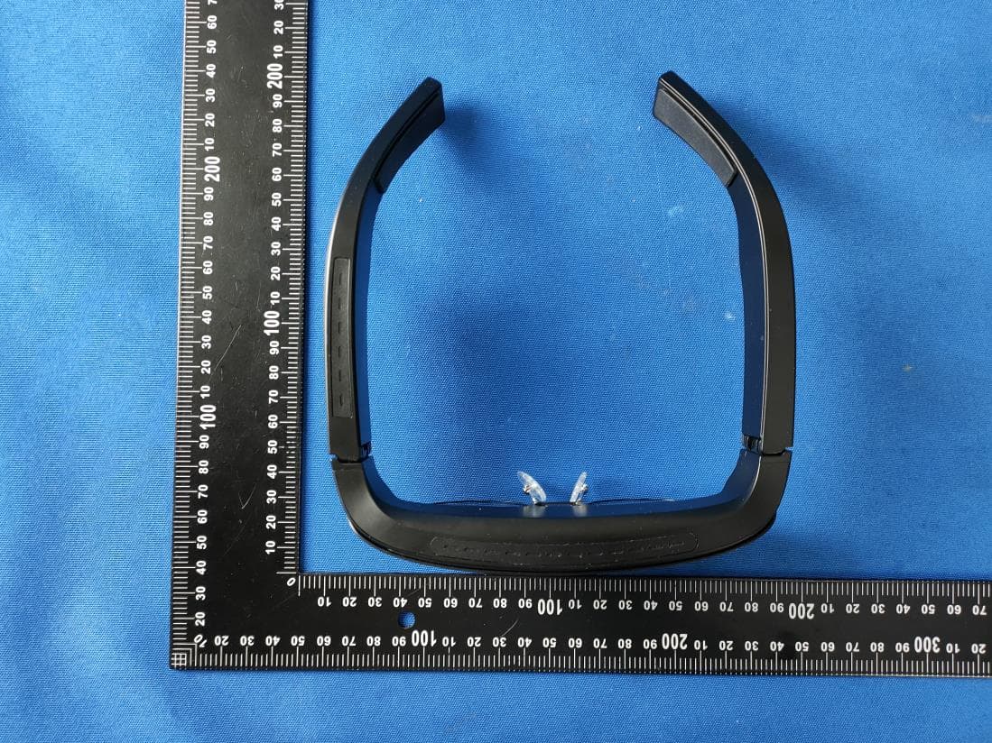
Click to zoom
Application Details
- Equipment Class
- NII - Unlicensed National Information Infrastructure TX
- Date of Grant
- Mar 26, 2024
- Application Purpose
- Original Equipment
- Date of Application
- Mar 26, 2024
- Equipment Note
- MyW AR GLASSES
- Frequency Range
- 5745.00000000 - 5825.00000000
- Company
- Brics Ship LLC
- Country
- United States
Documents & Files
Document Text
Text extracted from the exhibit documents filed with the FCC. Open a document above to read the original.
Users Manual
折线 User’ s Manual 说明书 成品尺寸:160X350mm 157双铜 风琴折 FrontBack Built-in apps Contents Safety Instruction For your safety, please read the following instructions before you use the product. Serious injury or property damage may be caused by improper operations. Do not try to repair the product on your own. Disconnect from power supply immediately if major failures occur. Major failures include: Smoke, peculiar smell or abnormal sound is discharged from the product. In the preceding scenarios, do not continue to use the product. Disconnect power supply immediately and contact professional staff for troubleshooting. Do not drop liquid, metal or anything combustible into the product. If any liquid or metal is dropped into the product, power off the product and disconnect power supply, then contact professional staff for solutions. Do not open the cover or change the product on your own. If inspection, adjustment, or maintenance is required, contact with local distributor for help. Do not place the product in high temperature environments. ◆ Do not place the product near a heat source, such as a radiator, a heat reservoir, a stove or other heating products. ◆ Do not expose the product to direct sunlight, which may cause high temperatures and subsequent faults in the product. Keep away from the product when you use a radio. The product complies with the international EMI standard to prevent radio interference. However, interference may still exist and causes noise in the radio. If noise occurs in the radio, try the following solutions. ◆ Adjust the direction of the radio antenna to avoid the interference from the product. ◆ Keep the radio away from the product. Do not damage the power cable. ◆ Do not damage, change, bend, or forcibly drag the power cable. ◆ Do not forcibly drag the cable when you pull out the power plug. If the power cable is damaged, please contact the local distributor to repair or replace it. ◆ The power cable in the accessory box is for this product only. Do not use it on other products. Additional advice: ◆ Use the product in an environment with comfortable lighting. It is harmful to your eyes to watch in a too bright or too dark environment. ◆ Relax your eyes after a period of time for watching. ◆ Adjust the volume to an appropriate level, especially at night. 刀模线 Install the prescription lens frame ( skip this step if not needed ) Customizing the Prescription Lenses: Take the prescription lens template from the accessories box to the local optical shops to customize your own prescription lenses (additional fees needed) if you wear glasses. Before customizing your prescription lenses, ask the optician to comprehensively evaluate the assembly method of the frame template to ensure that the thickness of the processed lenses and the width of the lens frame can meet the assembly requirements. The prescription lens frame adopts a magnetic design. Just align the magnetic position of the frame with the position of the glasses magnet and it will automat- ically attract. Selecting the nose pad There are three types of nose pads that come with the product as shown below: nose pad 1 (pre-installed on the glasses), nose pad 2, and nose pad 3. Select and adjust a nose pad and adjust the wearing position of the glasses for improved comfort and visual experience. Installing the nose pad To replace the nose pad, please use the screw driver to remove the screw, then pull out the nose pad in the opposite direction and remove the original nose pad, then insert it into the slot completely in the direction shown below and tighten up the screw and nose pad gasket. Storing the glasses in the Glasses Case When the glasses are not in use, it is recommended to store the glasses in the glasses case immediately. Tips: When you tidy up and store the data cables, prevent the USB-C metal heads of the data cables from scratching the optical lenses of the glasses. Installing the Sunglasses Sunglasses adopt a magnetic suction design, and simply align the magnetic suction position with the magnetic suction position on the front end of MyW to automatically adsorb them in place. 1 Installation and Use 2 Button Description Short press Long press Short press Short press Long press Short press Long press Turn on / off the display Power on / off Decrease the volume Increase the volume Increase the display brightness To pair remote control Decrease the display brightness Power MovementFunctions Button Button 1 Button 2 Button 1 and 2 Power Button 2 Button 1 The glasses have three buttons. The three buttons can be used for different functions by long or short press. Tips: – Pressing a button for less than 1 second, and then releasing is regarded as a short press. – Pressing a button for 2 seconds or more, and then releasing is regarded as a long press. Button Functions 3 c 5 FAQs&Troubleshooting 6 Operating the glasses 4 4.1 Pair to remote control when you use MyW glasses for the first time, please put out the remote control from the glasses box, then turn on the glasses and remote control, and follow system guidelines to pair. 4.2 Start to use When paired with remote control, the glasses will go to the home page, all applications can be viewed. The following figure shows applications that the system has. 4.3 System Settings Choose MyW Settings to enter system settings page. 4.3.1 Network Settings Enter the Network & Internet submenu to set Wi-Fi and hotspot. 4.3.2 Connected devices Settings Enter the Connected devices submenu to check connected devices or pair new device via Bluetooth. 4.3.3 Apps Settings Enter the Apps submenu to check recently opened apps and enter permission manager to control app access to your data. 4.3.4 Battery Enter the Battery submenu to check your battery status, set Battery Saver and Battery Manager. 4.3.5 Sound Enter the Sound submenu to check your Sound status and change them. 4.3.6 Storage Enter the Storage submenu to mange your glasses storage. 4.3.7 Accounts Enter the Accounts submenu …
Text truncated - open the document above for the full version.
Attestation Statements
Brics Ship LLC 2.911 (d)(5)(i) Equipment Type Attestation v1.2 Section 2.911(d)(5)(i) Certification – Equipment Type Company name: Brics Ship LLC Address: 3410 Geary Blvd, Ste 243, San Francisco CA, 94118 Product Name: MyW AR GLASSES FCC ID: 2BFA8-ARGLASSES Model(s): MyW AR Glasses, MyW1, NRMyW1, NRMyW, MyW AR, NRMyW AR, MyWXXXXXX (X can be any alphanumeric: character, symbol or blank) 2.911(d)(5)(i) Equipment Type We, [Brics Ship LLC] (“the applicant”) certify that the equipment for which authorization is sought through certification is not: Prohibited from receiving an equipment authorization pursuant to § 2.903; of the FCC rules. Identified as an equipment type in the “Covered List” NOTE 1 Yours sincerely, Name: Victor Shelton Sanna Pinto Date: March 20, 2024 Title and Company name: CEO Brics Ship LLC NOTE 1 “Covered List”; is the List of Equipment and Services Covered By Section 2 of The Secure Networks Act, available at https://www.fcc.gov/supplychain/coveredlist References; 1) 986446 D01 Covered Equipment v01 https://apps.fcc.gov/oetcf/kdb/forms/FTSSearchResultPage.cfm?switch=P&id=325672 2) Federal Register document 2022-28263 published on 02/06/23 https://www.federalregister.gov/documents/2023/02/06/2022-28263/protecting-against-national-security-threats-to-the-com munications-supply-chain-through-the
Attestation Statements
Brics Ship LLC 2.911 (d)(5)(ii) Applicant Attestation v1.3 Section 2.911(d)(5)(ii) Certification – Applicant (Covered List ) Company name: Brics Ship LLC Address: 3410 Geary Blvd, Ste 243, San Francisco CA, 94118 Product Name: MyW AR GLASSES FCC ID: 2BFA8-ARGLASSES Model(s): MyW AR Glasses, MyW1, NRMyW1, NRMyW, MyW AR, NRMyW AR, MyWXXXXXX (X can be any alphanumeric: character, symbol or blank) 2.911(d)(5)(ii) Applicant filing We, [Brics Ship LLC] (“the applicant”) certify that, as of the date of the filing of the application, the applicant is not identified NOTE 1 on the “Covered List” NOTE 2 , established pursuant to § 1.50002 of this chapter, as an entity producing covered communications equipment. Yours sincerely, Name: Victor Shelton Sanna Pinto Date: March 20, 2024 Title and Company name: CEO Brics Ship LLC NOTE 1 Delete option not applicable to this application. NOTE 2 “Covered List”; is the List of Equipment and Services Covered By Section 2 of The Secure Networks Act, available at https://www.fcc.gov/supplychain/coveredlist References; 1)986446 D01 Covered Equipment v01 https://apps.fcc.gov/oetcf/kdb/forms/FTSSearchResultPage.cfm?switch=P&id=325672 2) Federal Register document 2022-28263 published on 02/06/23 https://www.federalregister.gov/documents/2023/02/06/2022-28263/protecting-against-national-security-threats-to-the-com munications-supply-chain-through-the
Attestation Statements
Brics Ship LLC * the applicant must designate a contact located in the United States for purposes of acting as the applicant’s agent for service of process, regardless of whether the applicant is a domestic or foreign entity. An applicant located in the United States may designate itself as the agent for service of process. U.S. Agent Designation for Service of Process - Certification Attestation Letter DATE 2024/3/20 ATTN.: Reviewing Engineer FCC ID: 2BFA8-ARGLASSES FRN: 0035073246 Per section 2.911(d)(7) of the FCC rules, Brics Ship LLC certifies that the equipment for which authorization is sought is designated to the following U.S. agent* for service of process: Company Name: Brics Ship LLC . FRN: 0035073246 Physical U.S. Company Address: 3410 Geary Blvd, Ste 243, San Francisco CA, 94118 Agent name: Victor Shelton Sanna Pinto Agent Email Address: 3410 Geary Blvd, Ste 243, San Francisco CA, 94118 Tel: +55 (11) 99478-8070 The above contact person accepts the obligation for service of process. The applicant accepts to maintain an agent for no less than one year after the grantee has terminated all marketing and importation or the conclusion of any Commission-related proceeding involving the equipment. Applicant Signed: Signed: Printed name: Victor Shelton Sanna Pinto Title: CEO Company Name: Brics Ship LLC Date: 3/28/2024 Agent Signed (if different to Applicant): Signed: Printed name: Victor Shelton Sanna Pinto Title: CEO Company Name: Brics Ship LLC Date: 3/28/2024
Cover Letter(s)
FCC Software Configuration Control Declaration Rev1.1.docx Brics Ship LLC FCC Software Configuration Control Declaration Date: March 20, 2024 Federal Communications Commission 7435 Oakland Mills Road Columbia, MD 21046 USA Attn: OET Dept. Product/ Model Number: Geodetic GNSS Receiver / i89 Regarding FCC Country Code Selection guidelines identified in KDB 594280. “All applications for equipment authorization for transmitters that can have radio parameters, or other technical parameters, reported to the Commission set by software must have an attestation indicating that no third party will have software, or configuration control, to program the device out of compliance of the technical rules under which it has been certified.” We declare that no third party will have software, or configuration control, to program the device out of compliance of the technical rules under which it has been certified. Name: Victor Shelton Sanna Pinto Date: March 20, 2024 Title: CEO Signature of applicant
Cover Letter(s)
Brics Ship LLC Agent Authorization Company: Brics Ship LLC Address: 3410 Geary Blvd, Ste 243, San Francisco CA, 94118 Product Name: MyW AR GLASSES Model Number(s): MyW AR Glasses, MyW1, NRMyW1, NRMyW, MyW AR, NRMyW AR, MyWXXXXXX (X can be any alphanumeric: character, symbol or blank) Product Description: MyW AR GLASSES We authorize MiCOM Labs Inc., 575 Boulder Court, Pleasanton, California 94566, USA, to act on our behalf on all matters concerning the certification of above named equipment. We declare that MiCOM Labs Inc. is allowed to forward all information related to the approval and certification of equipment to the regulatory agencies as required and to discuss any issues concerning the approval application. Any and all acts carried out by MiCOM Labs on our behalf shall have the same effect as acts of our own. Signature: Date: 03/20/2024 Name: Victor Shelton Sanna Pinto Title: CEO Company: Brics Ship LLC
Cover Letter(s)
Brics Ship LLC Letter of Authorization Company: Brics Ship LLC Address: 3410 Geary Blvd, Ste 243, San Francisco CA, 94118 Product Name: MyW AR GLASSES Model Number(s): MyW AR Glasses, MyW1, NRMyW1, NRMyW, MyW AR, NRMyW AR, MyWXXXXXX (X can be any alphanumeric: character, symbol or blank) We authorize MiCOM Labs Inc., 575 Boulder Court, Pleasanton, California 94566, USA, to act on our behalf on all matters concerning the certification of above named equipment. We declare that MiCOM Labs Inc. is allowed to forward all information related to the approval and certification of equipment to the regulatory agencies as required and to discuss any issues concerning the approval application. Any and all acts carried out by MiCOM Labs on our behalf shall have the same effect as acts of our own. Signature: Date: 2024-03-20 Name: Victor Shelton Sanna Pinto Title: CEO Company: Brics Ship LLC
Cover Letter(s)
Differences Description We Brics Ship LLC state: Product name: MyW AR, MyW AR Glasses Model: MyW AR Glasses, MyW1, NRMyW1,NRMyW,MyW AR, NRMyW AR, MyWXXXXXX (X can be any alphanumeric: character , symbol or blank) ),NRMyWXXXXXX(X can be any alphanumeric: character , symbol or blank) All models of all models of PCB design, software, electric circuit, radio frequency characteristics, appearance are consistent 2024-03-20 Name Victor Shelton Sanna Pinto Position CEO Company Name Brics Ship LLC Address 3410 Geary Blvd, Ste 243, San Francisco CA, 94118 Tel +55 (11) 99478-8070 Fax / Email [email protected] (Signature)
External Photos
FCC ID: 2BFA8-ARGLASSES FCC ID: 2BFA8-ARGLASSES FCC ID: 2BFA8-ARGLASSES FCC ID: 2BFA8-ARGLASSES
ID Label/Location Info
4.5cm 1.0cm Label Location FCC ID: 2BFA8-ARGLASSES Brics Ship LLC Product name: MyW AR GLASSES This device complies with Part 15 of the FCC Rules. Operation is subject to the following two conditions: (1) this device may not cause harmful interference, and (2) this device must accept any interference received, including interference that may cause undesired operation.
Internal Photos
FCC ID: 2BFA8-ARGLASSES FCC ID: 2BFA8-ARGLASSES FCC ID: 2BFA8-ARGLASSES FCC ID: 2BFA8-ARGLASSES FCC ID: 2BFA8-ARGLASSES FCC ID: 2BFA8-ARGLASSES FCC ID: 2BFA8-ARGLASSES FCC ID: 2BFA8-ARGLASSES FCC ID: 2BFA8-ARGLASSES FCC ID: 2BFA8-ARGLASSES FCC ID: 2BFA8-ARGLASSES FCC ID: 2BFA8-ARGLASSES
RF Exposure Info
FCC ID: 2BFA8-ARGLASSES RF Exposure evaluation According to 447498 D01 General RF Exposure Guidance v06 The 1-g and 10-g SAR test exclusion thresholds for 100 MHz to 6 GHz at test separation distances ≤ 50 mm are determined by: [(max. power of channel, including tune-up tolerance, mW)/(min. test separation distance, mm)] ·[√f(GHz)] ≤ 3.0 for 1-g SAR and ≤ 7.5 for 10-g extremity SAR, where f(GHz) is the RF channel transmit frequency in GHz Power and distance are rounded to the nearest mW and mm before calculation The result is rounded to one decimal place for comparison Worse case is as below: For BLE: [2402MHz: -6.429dBm(0.228 mW) output power] (0.228mW /5mm) ·[√2.402 (GHz)]= 0.071 <3.0 for 1-g SAR For EDR: [2402MHz: 3.655dBm(2.320 mW) output power] (2.320mW /5mm) ·[√2.402 (GHz)]=0.719 <3.0 for 1-g SAR For 2.4G WIFI: [2437MHz: 7.962dBm(6.255 mW) output power] (6.255mW /5mm) ·[√2.437 (GHz)]= 1.953 <3.0 for 1-g SAR For 5G WIFI: [5230MHz: 6.965dBm(4.972 mW) output power] (4.972 mW /5mm) ·[√5.239 (GHz)]= 2.274 <3.0 for 1-g SAR Maximum Simultaneous transmission BT4.1+5G WIFI: 0.710+2.274=2.993<3.0 for 1-g SAR Then SAR evaluation is not required
Test Report
ALPHA's reports is using a digital certificate that is trusted on Adobe's official server. If there is no digital certificate or the digital certificate shows damaged in your report. Please do not accept the report. E-mail: [email protected] Tel: 4008300895 Website: http://www.a-lab.cn/certificate FCC TEST REPORT FCC ID: 2BFA8-ARGLASSES On Behalf of Brics Ship LLC MyW AR GLASSES Model No.: MyW AR Glasses, MyW1, NRMyW1, NRMyW, MyW AR, NRMyW AR, MyWXXXXXX (X can be any alphanumeric: character, symbol or blank) Prepared for : Brics Ship LLC Address : 3410 Geary Blvd, Ste 243, San Francisco CA, 94118 Prepared By : Shenzhen Alpha Product Testing Co., Ltd. Address : Building i, No.2, Lixin Road, Fuyong Street, Bao'an District, 518103, Shenzhen, Guangdong, China Report Number : A2311295-C01-R02 Date of Receipt : December 13, 2023 Date of Test : December 13, 2023-January 12, 2024 Date of Report : March 13, 2024 Version Number : V0 Test Result : Pass Page 2 of 168 Report No.: A2311295-C01-R02 TABLE OF CONTENTS Description Page 1 TEST SUMMARY ..................................................................................................................................... 5 1.1 MEASUREMENT UNCERTAINTY............................................................................................................. 5 2 GENERAL INFORMATION ...................................................................................................................... 6 2.1 GENERAL DESCRIPTION OF EUT ......................................................................................................... 6 2.2 TEST MODE ........................................................................................................................................ 7 2.3 TEST FACILITY .................................................................................................................................... 7 2.4 DESCRIPTION OF SUPPORT UNITS ....................................................................................................... 7 2.5 DEVIATION FROM STANDARDS ............................................................................................................. 7 2.6 ABNORMALITIES FROM STANDARD CONDITIONS.................................................................................... 7 2.7 OTHER INFORMATION REQUESTED BY THE CUSTOMER ......................................................................... 7 2.8 ADDITIONAL INSTRUCTIONS ................................................................................................................. 7 3 TEST INSTRUMENTS LIST ..................................................................................................................... 8 4 TEST RESULTS AND MEASUREMENT DATA ...................................................................................... 9 4.1 ANTENNA REQUIREMENT: .................................................................................................................... 9 4.2 CONDUCTED EMISSIONS ................................................................................................................... 10 4.3 EMISSION BANDWIDTH AND 99% OCCUPIED BANDWIDTH .................................................................... 13 4.4 PEAK TRANSMIT POWER ................................................................................................................... 76 4.5 POWER SPECTRAL DENSITY ............................................................................................................ 108 4.6 BAND EDGE .................................................................................................................................... 140 4.7 RADIATED EMISSION ....................................................................................................................... 162 Page 3 of 168 Report No.: A2311295-C01-R02 TEST REPORT DECLARATION Applicant : Brics Ship LLC Address : 3410 Geary Blvd, Ste 243, San Francisco CA, 94118 Manufacturer : SHENZHEN MYW TECHNOLOGY CO., LIMITED Address : Room 1101, Building 1, Dianda Guyuan Industrial Park, Mashantou Community, Matian Street, Guangming District, Shenzhen, China EUT Description : MyW AR GLASSES (A) Model No. : MyW AR Glasses, MyW1, NRMyW1, NRMyW, MyW AR, NRMyW AR, MyWXXXXXX (X can be any alphanumeric: character, symbol or blank) (B) Trademark : MYW Measurement Standard Used: FCC Rules and Regulations Part 15 Subpart E The device described above is tested by Shenzhen Alpha Product Testing Co., Ltd. to determine the maximum emission levels emanating from the device. The maximum emission levels are compared to the FCC Part 15 Subpart E limits both conducted and radiated emissions. The test results are contained in this test report and Shenzhen Alpha Product Testing Co., Ltd. is assumed of full responsibility for the accuracy and completeness of these tests. After the test, our opinion is that EUT compliance with the requirement of the above standards. This report applies to above tested sample only. This report shall not be reproduced in parts without written approval of Shenzhen Alpha Product Testing Co., Ltd. Tested by (name + signature).........: Yannis Wen Project Engineer Approved by (name + signature).......: Reak Yang Project Manager Date of issue................................: March 13, 2024 Page 4 of 168 Report No.: A2311295-C01-R02 Revision History Revision Issue Date Revisions Revised By V0 March 13, 2024 Initial released Issue Yannis Wen Page 5 of 168 Report No.: A2311295-C01-R02 1 Test Summary Test Item Section in CFR 47 Result Antenna requirement Section 15.203 Section 7.1.4 PASS AC Power Line Conducted Emission Section 15.207 Section 7.2.4 PASS Peak Transmit Power Section 15.407(a) PASS Power Spectral Density Section 15.407(a) PASS Undesirable Emission Section 15.407(b) PASS Radiated Emission Section 15.407(b)&15.209 Section 5.5 PASS Band Edge 15.205 PASS Remark: 1. Pass: The EUT complies with the essential requirements in th…
Text truncated - open the document above for the full version.
Test Report
Page 54 of 168 Report No.: A2311295-C01-R02 OBW NVNT a 5500MHz Ant1 OBW NVNT a 5580MHz Ant1 Page 55 of 168 Report No.: A2311295-C01-R02 OBW NVNT a 5700MHz Ant1 OBW NVNT ac20 5500MHz Ant1 Page 56 of 168 Report No.: A2311295-C01-R02 OBW NVNT ac20 5580MHz Ant1 OBW NVNT ac20 5700MHz Ant1 Page 57 of 168 Report No.: A2311295-C01-R02 OBW NVNT ac40 5510MHz Ant1 OBW NVNT ac40 5670MHz Ant1 Page 58 of 168 Report No.: A2311295-C01-R02 OBW NVNT ac80 5530MHz Ant1 OBW NVNT n20 5500MHz Ant1 Page 59 of 168 Report No.: A2311295-C01-R02 OBW NVNT n20 5580MHz Ant1 OBW NVNT n20 5700MHz Ant1 Page 60 of 168 Report No.: A2311295-C01-R02 OBW NVNT n40 5510MHz Ant1 OBW NVNT n40 5670MHz Ant1 Page 61 of 168 Report No.: A2311295-C01-R02 Band 4 (5725-5850 MHz): -6dB Bandwidth Condition Mode Frequency (MHz) Antenna -6 dB Bandwidth (MHz) Limit -6 dB Bandwidth (MHz) Verdict NVNT a 5745 Ant1 14.22 0.5 Pass NVNT a 5785 Ant1 15 0.5 Pass NVNT a 5825 Ant1 16.32 0.5 Pass NVNT ac20 5745 Ant1 13.59 0.5 Pass NVNT ac20 5785 Ant1 12.84 0.5 Pass NVNT ac20 5825 Ant1 13.47 0.5 Pass NVNT ac40 5755 Ant1 35.04 0.5 Pass NVNT ac40 5795 Ant1 34.14 0.5 Pass NVNT ac80 5775 Ant1 75.12 0.5 Pass NVNT n20 5745 Ant1 17.58 0.5 Pass NVNT n20 5785 Ant1 15.06 0.5 Pass NVNT n20 5825 Ant1 17.58 0.5 Pass NVNT n40 5755 Ant1 33.84 0.5 Pass NVNT n40 5795 Ant1 31.92 0.5 Pass -6dB Bandwidth NVNT a 5745MHz Ant1 Page 62 of 168 Report No.: A2311295-C01-R02 -6dB Bandwidth NVNT a 5785MHz Ant1 -6dB Bandwidth NVNT a 5825MHz Ant1 Page 63 of 168 Report No.: A2311295-C01-R02 -6dB Bandwidth NVNT ac20 5745MHz Ant1 -6dB Bandwidth NVNT ac20 5785MHz Ant1 Page 64 of 168 Report No.: A2311295-C01-R02 -6dB Bandwidth NVNT ac20 5825MHz Ant1 -6dB Bandwidth NVNT ac40 5755MHz Ant1 Page 65 of 168 Report No.: A2311295-C01-R02 -6dB Bandwidth NVNT ac40 5795MHz Ant1 -6dB Bandwidth NVNT ac80 5775MHz Ant1 Page 66 of 168 Report No.: A2311295-C01-R02 -6dB Bandwidth NVNT n20 5745MHz Ant1 -6dB Bandwidth NVNT n20 5785MHz Ant1 Page 67 of 168 Report No.: A2311295-C01-R02 -6dB Bandwidth NVNT n20 5825MHz Ant1 -6dB Bandwidth NVNT n40 5755MHz Ant1 Page 68 of 168 Report No.: A2311295-C01-R02 -6dB Bandwidth NVNT n40 5795MHz Ant1 Occupied Channel Bandwidth Condition Mode Frequency (MHz) Antenna 99% OBW (MHz) NVNT a 5745 Ant1 16.364 NVNT a 5785 Ant1 16.394 NVNT a 5825 Ant1 16.334 NVNT ac20 5745 Ant1 17.682 NVNT ac20 5785 Ant1 17.532 NVNT ac20 5825 Ant1 17.532 NVNT ac40 5755 Ant1 36.204 NVNT ac40 5795 Ant1 36.024 NVNT ac80 5775 Ant1 75.405 NVNT n20 5745 Ant1 17.652 NVNT n20 5785 Ant1 17.502 NVNT n20 5825 Ant1 17.532 NVNT n40 5755 Ant1 35.964 NVNT n40 5795 Ant1 36.024 Page 69 of 168 Report No.: A2311295-C01-R02 OBW NVNT a 5745MHz Ant1 OBW NVNT a 5785MHz Ant1 Page 70 of 168 Report No.: A2311295-C01-R02 OBW NVNT a 5825MHz Ant1 OBW NVNT ac20 5745MHz Ant1 Page 71 of 168 Report No.: A2311295-C01-R02 OBW NVNT ac20 5785MHz Ant1 OBW NVNT ac20 5825MHz Ant1 Page 72 of 168 Report No.: A2311295-C01-R02 OBW NVNT ac40 5755MHz Ant1 OBW NVNT ac40 5795MHz Ant1 Page 73 of 168 Report No.: A2311295-C01-R02 OBW NVNT ac80 5775MHz Ant1 OBW NVNT n20 5745MHz Ant1 Page 74 of 168 Report No.: A2311295-C01-R02 OBW NVNT n20 5785MHz Ant1 OBW NVNT n20 5825MHz Ant1 Page 75 of 168 Report No.: A2311295-C01-R02 OBW NVNT n40 5755MHz Ant1 OBW NVNT n40 5795MHz Ant1 Page 76 of 168 Report No.: A2311295-C01-R02 4.4 Peak Transmit Power Test Requirement: FCC Part15 E Section 15.407, RSS-247 Issue 2 Test Method: KDB 789033 D02 General UNII Test Procedures New Rules v02r01 Limit: For the band 5.15-5.25GHz, 5.25-5.35GHz, 5.47-5.725GHz, the maximum conducted output power over the frequency bands of operation shall not exceed 250mW. For the band 5.725-5.85GHz, the maximum conducted output power over the frequency bands of operation shall not exceed 1W. Test setup: Test procedure: Measurement using an RF average power meter (i) Measurements may be performed using a wideband RF power meter with a thermocouple detector or equivalent if all of the conditions listed below are satisfied a) The EUT is configured to transmit continuously or to transmit with a constant duty cycle. b) At all times when the EUT is transmitting, it must be transmitting at its maximum power control level. c) The integration period of the power meter exceeds the repetition period of the transmitted signal by at least a factor of five. (ii) If the transmitter does not transmit continuously, measure the duty cycle, x, of the transmitter output signal as described in section B). (iii) Measure the average power of the transmitter. This measurement is an average over both the on and off periods of the transmitter. (iv) Adjust the measurement in dBm by adding 10 log(1/x) where x is the duty cycle (e.g., 10log(1/0.25) if the duty cycle is 25 percent). Test Instruments: Refer to section 5.10 for details Test mode: Refer to section 5.3 for details Test results: Pass Page 77 of 168 Report No.: A2311295-C01-R02 Measurement Data Band 1 (5150-5250 MHz) Condition Mode Frequency (MHz) Antenna Conducted Power (dBm) EIRP (dBm) Limit (dBm) Verdict NVNT a 5180 Ant1 1.248 6.208 24 Pass NVNT a 5200 Ant1 1.35 6.31 24 Pass NVNT a 5240 Ant1 1.644 6.604 24 Pass NVNT ac20 5180 Ant1 1.584 6.544 24 Pass NVNT ac20 5200 Ant1 1.698 6.658 24 Pass NVNT ac20 5240 Ant1 1.414 6.374 24 Pass NVNT ac40 5190 Ant1 1.811 6.771 24 Pass NVNT ac40 5230 Ant1 2.005 6.965 24 Pass NVNT ac80 5210 Ant1 1.721 6.681 24 Pass NVNT n20 5180 Ant1 1.823 6.783 24 Pass NVNT n20 5200 Ant1 1.898 6.858 24 Pass NVNT n20 5240 Ant1 1.578 6.538 24 Pass NVNT n40 5190 Ant1 1.668 6.628 24 Pass NVNT n40 5230 Ant1 1.532 6.492 24 Pass Duty Cycle Condition Mode Frequency (MHz) Antenna Duty Cycle (%) Correction Factor (dB) NVNT a 5180 Ant1 100 0 NVNT a 5200 Ant1 100 0 NVNT a 5240 Ant1 100 0 NVNT ac20 5180 Ant1 100 0 NVNT ac20 5200 Ant1 100 0 NVNT ac20 5240 Ant1 100 0 NVNT ac40 5190 Ant1 100 0 NVNT ac40 5230 Ant1 100 0 NVNT ac80 5210 Ant1 100 0 NVNT n20 5180 Ant1 100 0 NVNT n20 5200 Ant1 100 0 NVNT n20 5240 Ant1 100 0 NVNT n40 5190 Ant1 100 0 NVNT n40 5230 Ant…
Text truncated - open the document above for the full version.
Test Report
Page 97 of 168 Report No.: A2311295-C01-R02 Duty Cycle NVNT n20 5500MHz Ant1 Duty Cycle NVNT n20 5580MHz Ant1 Page 98 of 168 Report No.: A2311295-C01-R02 Duty Cycle NVNT n20 5700MHz Ant1 Duty Cycle NVNT n40 5510MHz Ant1 Page 99 of 168 Report No.: A2311295-C01-R02 Duty Cycle NVNT n40 5670MHz Ant1 Page 100 of 168 Report No.: A2311295-C01-R02 Band 4 (5725 – 5850 MHz) Condition Mode Frequency (MHz) Antenna Conducted Power (dBm) Limit (dBm) Verdict NVNT a 5745 Ant1 6.082 30 Pass NVNT a 5785 Ant1 6.707 30 Pass NVNT a 5825 Ant1 6.611 30 Pass NVNT ac20 5745 Ant1 6.578 30 Pass NVNT ac20 5785 Ant1 6.401 30 Pass NVNT ac20 5825 Ant1 6.873 30 Pass NVNT ac40 5755 Ant1 6.265 30 Pass NVNT ac40 5795 Ant1 6.142 30 Pass NVNT ac80 5775 Ant1 6.42 30 Pass NVNT n20 5745 Ant1 6.188 30 Pass NVNT n20 5785 Ant1 6.279 30 Pass NVNT n20 5825 Ant1 6.288 30 Pass NVNT n40 5755 Ant1 6.309 30 Pass NVNT n40 5795 Ant1 6.939 30 Pass Duty Cycle Condition Mode Frequency (MHz) Antenna Duty Cycle (%) Correction Factor (dB) NVNT a 5745 Ant1 100 0 NVNT a 5785 Ant1 100 0 NVNT a 5825 Ant1 100 0 NVNT ac20 5745 Ant1 100 0 NVNT ac20 5785 Ant1 100 0 NVNT ac20 5825 Ant1 100 0 NVNT ac40 5755 Ant1 100 0 NVNT ac40 5795 Ant1 100 0 NVNT ac80 5775 Ant1 100 0 NVNT n20 5745 Ant1 100 0 NVNT n20 5785 Ant1 100 0 NVNT n20 5825 Ant1 100 0 NVNT n40 5755 Ant1 100 0 NVNT n40 5795 Ant1 100 0 Duty Cycle NVNT a 5745MHz Ant1 Page 101 of 168 Report No.: A2311295-C01-R02 Duty Cycle NVNT a 5785MHz Ant1 Duty Cycle NVNT a 5825MHz Ant1 Page 102 of 168 Report No.: A2311295-C01-R02 Duty Cycle NVNT ac20 5745MHz Ant1 Duty Cycle NVNT ac20 5785MHz Ant1 Page 103 of 168 Report No.: A2311295-C01-R02 Duty Cycle NVNT ac20 5825MHz Ant1 Duty Cycle NVNT ac40 5755MHz Ant1 Page 104 of 168 Report No.: A2311295-C01-R02 Duty Cycle NVNT ac40 5795MHz Ant1 Duty Cycle NVNT ac80 5775MHz Ant1 Page 105 of 168 Report No.: A2311295-C01-R02 Duty Cycle NVNT n20 5745MHz Ant1 Duty Cycle NVNT n20 5785MHz Ant1 Page 106 of 168 Report No.: A2311295-C01-R02 Duty Cycle NVNT n20 5825MHz Ant1 Duty Cycle NVNT n40 5755MHz Ant1 Page 107 of 168 Report No.: A2311295-C01-R02 Duty Cycle NVNT n40 5795MHz Ant1 Page 108 of 168 Report No.: A2311295-C01-R02 4.5 Power Spectral Density Test Requirement: FCC Part15 E Section 15.407, RSS-247 Issue 2 Test Method: KDB 789033 D02 General UNII Test Procedures New Rules v02r01 Limit: ≤11.00dBm/MHz for 5150MHz-5250MHz, 5250-5350MHz and 5470-5725 MHz ≤30.00dBm/500KHz for 5725MHz-5850MHz Test …
Text truncated - open the document above for the full version.
Contact Information
Applicant
Victor Shelton Sanna Pinto(CEO)
Technical Contact
Test Firm
Shenzhen Alpha Product Testing Co., LTD.Real Yak
[email protected]+86 755 29766001
Technical Specifications
| # | Rule Parts | Frequency Range | Power Output |
|---|---|---|---|
| 4 | 15E | 5.75 GHz - 5.83 GHz | 4.94 mW |
Other Applications from Brics Ship LLC
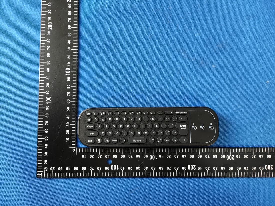
2BFA8-MYW-A-1
Mar 27, 2024Remote Control
Equipment Class
DTS - Digital Transmission System