2BG2G-ADSAIFC01Audio-visual display stand
Shanghai Forsung industry Co.,Ltd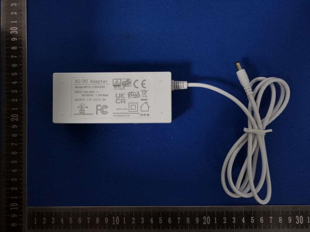
Click to zoom
Application Details
- Equipment Class
- DTS - Digital Transmission System
- Date of Grant
- Mar 05, 2026
- Application Purpose
- Original Equipment
- Equipment Note
- Audio-visual display stand
- Frequency Range
- 2412.00000000 - 2462.00000000
- Country
- China
Documents & Files
Document Text
Text extracted from the exhibit documents filed with the FCC. Open a document above to read the original.
Users Manual
Viaimearbuds Demonstration Prop User Manual 1.Overview 1.1 The device supports both OTA and hardware data transfer update modes; prioritizes background remote push updates. 1.2 Default state: Upon startup, the “standby video” loops continuously without user interaction. After video or audio playback completes with no further action, it reverts to “standby video” playback. 1.3 Power adapter input: 100-240V, 50-60Hz; output: 12V, 5A. 2. Props Structural Components Introduction 2.1 Front View of Props Display*1 Props Main Stand*1 Function buttons*6 Demo unit*1 Display Model*1 2.2 Prop Back Interface Description 12V Main Power Input Main Power Switch Price Tag Holder Base*1 2.3 Key Descriptions Text conversion TranslationSound Quality Experience Volume-Volume+ AIFunction “Transcribe” + ‘Translate’ + “AI Features” button: Click once to start playing the video associated with the current button; Click again to pause the video; Double-click to restart the video from the beginning; After the video finishes playing, return to the screensaver video; Return to the screensaver interface if no action is taken for 2 minutes. Audio Experience Button: Press once to start video playback while audio streams through headphones; Press again to pause both audio and video; Upon completion of audio/video playback, returns to screensaver video; Returns to screensaver interface after 2 minutes of inactivity. Volume Down/Volume Up: Each press adjusts volume by 10%; long presses are ineffective. OFF/ON Power Switch Magnetic Power Delivery + Signal Transmission 2.4 Interface Specifications for the Left Side of the Prop TF card, used for copying files OTG port, connect to a computer using a USB cable USB 3.0, for later video replacement or mouse connection operations 2.4.1 Remove the cover plate from the left-hand notch of the tool as shown in the diagram. 2.4.2 Exposed motherboard interface for copying files or connecting a mouse for operation 3. Installation and Use 3.1 Finished Product Photos 3.2 Accessories Front BackRightLeft Display stand base*1 + Price tag base*1 Display stand back panel*1 Power adapter*1 + Remote control*1 Data box*1 + Connecting screws*2 + Allen wrench*1 3.3 Installation Instructions 3.3.1 Place the display stand base flat on the tabletop. 3.3.2 Attach the display stand back panel to the rear of the base and secure it with two connecting screws. 3.3.3 Turn the screws clockwise to tighten the two screws. ProblemSolution The play button is not working Attempt a power cycle restart of the device; The device does not light up when powered on. Check the power supply before trying again. Bluetooth headphones disconnect Follow the pairing procedure in Step 5.5; The remote control is not functioning 1.Replace the remote control batteries and try again; 2.Use a mouse connected to the USB port for operation; 4. Frequently Asked Questions and Solutions 5. After-Sales Support Should you encounter any issues with this display stand, please contact our after-sales service hotline at 400 103 6861. We will address the matter promptly. 3.3.4 Insert the power plug into the socket. 3.3.5 Attach the document holder to the left side of the display unit as shown in the diagram; place the remote control in the compartment behind the document holder.Attachthe price tag base to the front of the display unit.Turnon the power switch to complete assembly of the display unit. FCC Warning This device complies with Part 15 of the FCC Rules. Operation is subject to the following two conditions: (1) This device may not cause harmful interference, and (2) this device must accept any interference received, including interference that may cause undesired operation. NOTE 1: This equipment has been tested and found to comply with the limits for a Class B digital device, pursuant to part 15 of the FCC Rules. These limits are designed to provide reasonable protection against harmful interference in a residential installation. This equipment generates, uses and can radiate radio frequency energy and, if not installed and used in accordance with the instructions, may cause harmful interference to radio communications. However, there is no guarantee that interference will not occur in a particular installation. If this equipment does cause harmful interference to radio or television reception, which can be determined by turning the equipment off and on, the user is encouraged to try to correct the interference by one or more of the following measures: - Reorient or relocate the receiving antenna. - Increase the separation between the equipment and receiver. -Connect the equipment into an outlet on a circuit different from that to which the receiver is connected. -Consult the dealer or an experienced radio/TV technician for help. NOTE 2: Any changes or modifications to this unit not expressly approved by the party responsible for compliance could void the user's authority to operate the equipment. RF Exposure Statement To maintain compliance with FCC'S RF Exposure guidelines, This equipment should be installed and operated with minimum 20cm between the radiator and your body. This device and its antenna(s) must not be co-located or operation in conjunction with any other antenna or transmitter.
Attestation Statements
Shanghai Forsung industry Co.,Ltd Covered Equipment Certification Attestation Letter 3/2/2026 Federal Communications Commission Authorization and Evaluation Division 7435 Oakland Mills Road Columbia, MD 21046 USA ATTN.: Reviewing Engineer FCC ID: 2BG2G-ADSAIFC01 Shanghai Forsung industry Co.,Ltd (“the applicant”) certifies that the equipment for which authorization is sought is not “covered” equipment prohibited from receiving an equipment authorization pursuant to section 2.903 of the FCC rules. Note: If the equipment for which the applicant seeks authorization is produced by any of the entities identified on the current Covered List, the applicant should include an explanation on why the equipment is not “covered” equipment. Shanghai Forsung industry Co.,Ltd (“the applicant”) certifies that, as of the date of the filing of the application, the applicant is not identified on the Covered List (as a specifically named entity or any of its subsidiaries or affiliates) as an entity producing “covered” equipment. Shanghai Forsung industry Co.,Ltd (“the applicant”) certifies that the equipment for which authorization is sought does not include cybersecurity or anti-virus software produced or provided by Kaspersky Lab, Inc. or any of its successors and assignees, including equipment with integrated Kaspersky Lab, Inc. (or any of its successors and assignees) cybersecurity or anti-virus software pursuant to DA-24-886 and KDB 986446 D01 Covered Equipment Guidance section B(2a). Signed: Printed name: Cathy Hong Title: manager Company Name: Shanghai Forsung industry Co.,Ltd Date: 3/2/2026
Attestation Statements
Shanghai Forsung industry Co.,Ltd U.S. Agent Letter of Attestation To: Federal Communications Commission 7435 Oakland Mills Road, Columbia, MD 21046, USA Date: March 2, 2026 Ref: Attestation Statement – Part 2.911(d)(7) filing FCC ID: 2BG2G-ADSAIFC01 Shanghai Forsung industry Co.,Ltd(“the applicant”) certifies that, as of the date of the filing of the application, CLF Import and Export Limited (“the agent”) is our designated U.S. agent for service of process for the above reference FCC ID. The applicant accepts to maintain an agent for service of process in the United States for no less than one year after either the grantee has permanently terminated all marketing and importation of the applicable equipment within the U.S., or the conclusion of any Commission-related administrative or judicial proceeding involving the equipment, whichever is later. The applicant further acknowledges it is our responsibility to inform the FCC whenever the agent information changes. CLF Import and Export Limited ("the agent) understand it is the agent's obligation to accept service of process in the United States for matters related to the applicable equipment, and at the physical U.S. address and email address. Designated U.S. Agent Company Name: CLF Import and Export Limited FRN: 0033489683 Address: 1312 17th Street #692, Denver, CO 80202, United States Signature: Contact Person: David Chen Tel: +1 949 254 2565 Email: [email protected] Applicant Shanghai Forsung industry Co.,Ltd FRN: 0035567817 Address: No.8, Lane 2248, Liuxiang Road, Jiading District, Shanghai, China Signature: Contact Person: Cathy Hong Tel: 13538214502 Email: [email protected]
Cover Letter(s)
DATE: March 2, 2026 Federal Communications Commission Authorization & Evaluation Division 7345 Oakland Mills Road Columbia, Maryland 21046 Authority to Act as Agent On our behalf, I appoint Shenzhen CCUT Quality Technology Co., Ltd. (1F, Building 35, Changxing Technology Indstrl Park Changzhen Community, Yutang Street,Shenzhen,China) to act as our agent in the preparation of this application for equipment certification. I certify that submitted documents properly describe the device or system for which equipment certification is sought. I also certify that each unit manufactured, imported or marketed, as defined in the Federal Communications Commission’s regulations will have affixed to it a label identical to that submitted for approval with this application. For instances where our authorized agent signs the application for certification on our behalf, I acknowledge that all responsibility for complying with the terms and conditions for certification, still resides with Shanghai Forsung industry Co.,Ltd (No.8, Lane 2248, Liuxiang Road, Jiading District, Shanghai, China). <Signature> Name: Cathy Hong Title: manager Applicant Company: Shanghai Forsung industry Co.,Ltd
Cover Letter(s)
Date: March 2, 2026 Federal Communications Commission Authorization & Evaluation Division 7345 Oakland Mills Road Columbia, Maryland 21046 RE: LETTER OF AGENT AUTHORIZATION To Whom It May Concern: We, the undersigned, hereby authorize Compliance Testing, LLC to act on our behalf in all matters relating to application for equipment authorization, including the signing of all documents relating to these matters. We also hereby certify that no party to the application authorized hereunder is subject to the denial of benefits, including FCC benefits, pursuant to Section 5301 of the Anti-Drug Abuse Act of 1988, 21 U.S.C.853(a). Sincerely, <Signature> Name: Cathy Hong Title: manager Company: Shanghai Forsung industry Co.,Ltd
Cover Letter(s)
DATE: March 2, 2026 Equipment Autorisation Division Federal Communications Commission 7435 Oakland Mills Road Columbia, MD 21046 FCC ID: 2BG2G-ADSAIFC01 Product Name: Audio-visual display stand Request for Confidentiality Pursuant to Sections 0.457 and 0.459 of the commission’s rules, we hereby request that the following documents be held confidential: (List here the documents for which you are seeking confidentiality – for example ...) Schematics Block diagram Operation description These materials contain trade secrets and proprietary information and are not customarily released to the public. The public disclosure of this information might be harmful to the company and provide unjustified benefits to our competitors. <Signature> Name: Cathy Hong Title: manager Company: Shanghai Forsung industry Co.,Ltd
External Photos
Report No: SSP26010459-1&2E FCC ID: 2BG2G-ADSAIFC01 Annex of Test Report Annex A. EUT External Photos Model: ADS-AI-FC-01 EUT View 1 EUT View 2 Report No: SSP26010459-1&2E FCC ID: 2BG2G-ADSAIFC01 Annex of Test Report EUT View 3 EUT View 4 Report No: SSP26010459-1&2E FCC ID: 2BG2G-ADSAIFC01 Annex of Test Report EUT View 5 EUT View 6 Report No: SSP26010459-1&2E FCC ID: 2BG2G-ADSAIFC01 Annex of Test Report EUT View 7 EUT View 8 Report No: SSP26010459-1&2E FCC ID: 2BG2G-ADSAIFC01 Annex of Test Report EUT View 9 EUT View 10 Report No: SSP26010459-1&2E FCC ID: 2BG2G-ADSAIFC01 Annex of Test Report EUT View 11
ID Label/Location Info
Report No: SSP26010459-1&2E FCC ID: 2BG2G-ADSAIFC01 Annex of Test Report Annex D. Label and Inf ormation FCC Label Sample FCC Label Specifications Text is Black in color and is justified. Labels are printed in indelible ink on permanent adhesive backing or silk-screened onto the EUT or shall be affixed at a conspicuous location on the EUT. Where the EUT is constructed in two or more sections connected by wires and marketed together, the above statement is required to be affixed only to the main control unit. When the EUT is so small or for such use that it is not practicable to place the statement on it, the above information shall be placed in a prominent location in the instruction manual or pamphlet supplied to the user or, alternatively, shall be placed on the container in which the device is marketed. FCC Label Location
Internal Photos
Report No: SSP26010459-1&2E FCC ID: 2BG2G-ADSAIFC01 Annex of Test Report Annex B. EUT Internal Photos Model: ADS-AI-FC-01 EUT Internal View 1 EUT Internal View 2 Report No: SSP26010459-1&2E FCC ID: 2BG2G-ADSAIFC01 Annex of Test Report EUT Internal View 3 EUT Internal View 4 Report No: SSP26010459-1&2E FCC ID: 2BG2G-ADSAIFC01 Annex of Test Report EUT Internal View 5 EUT Internal View 6 Glue Stick Antenna Report No: SSP26010459-1&2E FCC ID: 2BG2G-ADSAIFC01 Annex of Test Report EUT Internal View 7 EUT Internal View 8 Report No: SSP26010459-1&2E FCC ID: 2BG2G-ADSAIFC01 Annex of Test Report EUT Internal View 9
RF Exposure Info
FCC ID: 2BG2G-ADSAIFC01 RF Exposure Evaluation Limits The criteria listed in the following table shall be used to evaluate the environment impact of human exposure to radio frequency (RF) radiation as specified in 1.1307(b) Limits for Maximum Permissible Exposure (MPE) Frequency range (MHz) Electric field strength (V/m) Magnetic field strength (A/m) Power density (mW/cm 2 ) Averaging time (minutes) (A) Limits for Occupational/Controlled Exposures 0.3–3.0 614 1.63 *(100) 6 3.0–30 1842/f 4.89/f *(900/f 2 ) 6 30–300 61.4 0.163 1.0 6 300–1500 f/300 6 1500–100,000 5 6 (B) Limits for General Population/Uncontrolled Exposure 0.3–1.34 614 1.63 *(100) 30 1.34–30 824/f 2.19/f *(180/f 2 ) 30 30–300 27.5 0.073 0.2 30 300–1500 f/1500 30 1500–100,000 1.0 30 f = frequency in MHz Friis transmission formula: Pd = (Pout*G)/(4*pi*r 2 ) Where Pd = power density in mW/cm 2 , Pout = output power to antenna in mW; G = gain of antenna in linear scale, Pi = 3.1416; R = distance between observation point and center of the radiator in cm Pd id the limit of MPE, 1 mW/cm 2 . If we know the maximum gain of the antenna and the total power input to the antenna, through the calculation, we will know the distance r where the MPE limit is reached. Test Procedure Software provided by client enabled the EUT to transmit and receive data at lowest, middle and highest channel individually. Test Result of RF Exposure Evaluation BR/EDR mode Mode Output power to antenna (dBm) Tune-up Power(dBm) Max Tune-up Power(dBm) Output power to antenna (mW) Power Density at R=20cm (mW/cm 2 ) Limit (mW/cm 2 ) Result 8DPSK 2.48 2(±1) 3 2 0.0006 1.0 PASS WiFi mode Mode Output power to antenna (dBm) Tune-up Power(dBm) Max Tune-up Power(dBm) Output power to antenna (mW) Power Density at R=20cm (mW/cm 2 ) Limit (mW/cm 2 ) Result 802.11b 13.33 13(±1) 14 25.12 0.0079 1.0 PASS Remark: antenna gain= 2dBi
Test Report
Report No: SSP26010459-2E FCC Test Report Page 1 of 50 FCC TEST REPORT FCC ID: 2BG2G-ADSAIFC01 Report No. : SSP26010459-2E Applicant : Shanghai Forsung industry Co.,Ltd Product Name : Audio-visual display stand Model Name : ADS-AI-FC-01 Test Standard : FCC Part 15.247 Date of Issue : 2026-03-05 Shenzhen CCUT Quality Technology Co., Ltd. 1F, Building 35, Changxing Technology Industrial Park, Yutang Street, Guangming District, Shenzhen, Guangdong, China; (Tel.:+86-755-23406590 website: www.ccuttest.com) This test report is limited to the above client company and the product model only. It may not be duplicated without prior permitted by Shenzhen CCUT Quality Technology Co., Ltd. Report No: SSP26010459-2E FCC Test Report Page 2 of 50 Test Report Basic Information Applicant..................................: Shanghai Forsung industry Co.,Ltd Address of Applicant...............: No.8, Lane 2248, Liuxiang Road, Jiading District, Shanghai, China Manufacturer..........................: Shanghai Forsung industry Co.,Ltd Address of Manufacturer........: No.8, Lane 2248, Liuxiang Road, Jiading District, Shanghai, China Product Name.........................: Audio-visual display stand Brand Name.............................: Forsung Main Model..............................: ADS-AI-FC-01 Series Models..........................: - Test Standard..........................: FCC Part 15 Subpart C KDB 558074 D01 15.247 Meas Guidance v05r02 ANSI C63.4-2014 ANSI C63.10-2020 Date of Test .............................: 2026-01-16 to 2026-03-04 Test Result...............................: PASS Tested By ................................: (Walker Wu) Reviewed By............................: (Lorzix Luo) Authorized Signatory............: (Lahm Peng) Note : This test report is limited to the above client company and the product model only. It may not be duplicated without prior permitted by Shenzhen CCUT Quality Technology Co., Ltd.. All test data presented in this test report is only applicable to presented test sample. Report No: SSP26010459-2E FCC Test Report Page 3 of 50 CONTENTS 1. General Information ....................................................................................................................................................5 1.1 Product Information .............................................................................................................................................5 1.2 Test Setup Information..........................................................................................................................................6 1.3 Compliance Standards ...........................................................................................................................................7 1.4 Test Facilities ........................................................................................................................................................7 1.5 List of Measurement Instruments ..........................................................................................................................8 1.6 Measurement Uncertainty .....................................................................................................................................9 2. Summary of Test Results ........................................................................................................................................... 10 3. Antenna Requirement ............................................................................................................................................... 11 3.1 Standard and Limit.............................................................................................................................................. 11 3.2 Test Result .......................................................................................................................................................... 11 4. Conducted Emissions ................................................................................................................................................ 12 4.1 Standard and Limit.............................................................................................................................................. 12 4.2 Test Procedure.................................................................................................................................................... 12 4.3 Test Data and Results .......................................................................................................................................... 13 5. Radiated Emissions ................................................................................................................................................... 16 5.1 Standard and Limit.............................................................................................................................................. 16 5.2 Test Procedure.................................................................................................................................................... 16 5.3 Test Data and Results .......................................................................................................................................... 18 6. Band-edge Emissions(Radiated) ............................................................................................................................... 22 6.1 Standard and Limit.............................................................................................................................................. 22 6.2 Test Procedure.................................................................................................................................................... 22 6.3 Test Data and Results .......................................................................................................................................... 22 7. Maximum Conducted Output Pow…
Text truncated - open the document above for the full version.
Test Report
深圳市华圣电子有限公司 Shenzhen Hong Lian Xing Technology Co., Ltd. 样品承认书 SPECIFICATION FOR APPROVAL 客户名称: CUSTOMER NAME 产品名称: 2.4G 2dB圆柱胶棒天线 Glue Stick Antenna 产品型号: hlx -2.4G-015 PAPT MODEL 承 认 栏 供应商确认:客户确认: 拟定审核批准确认审核承认 罗斌聂星亮郭秀清 一、电气性能 Electrical factor 1.频率范围 Frenquency range2400MHZ-2450MHZ-2500MHZ 2.输入阻抗 Impedance 50Ω 3.驻波比 VSWR ≤1.5 4.增益 Gain2dBi 5.极化方式 Polarization vertical 6.辐射方向 Radiation omnibearing 7.功率容量 Maximun power lnput -watts50W 二、机械特性 Mechanical performance 1.尺寸 Dimension 11cm ±2mm 2.接头 Connector sma Internal screw and internal needle 3.外罩材料 Radome material TPE、ABS 4.外罩颜色 Radome color black 5.工作温度 Working temperature -20°C ~ 85°C 6.存放温度 Storage temperature -40°C ~ 90°C 实物图picture of real products: 内图inner picture 外观图external view 三、性能测试 1.阻抗图 SMITH 2. 驻波图 VSWR 3. 回损图 RETURN LOSS
Test Setup Photos
Report No: SSP26010459-1&2E FCC ID: 2BG2G-ADSAIFC01 Annex of Test Report Annex C. Test Photos Conducted Emission Test View Radiated Emission Test View Below 1GHz Report No: SSP26010459-1&2E FCC ID: 2BG2G-ADSAIFC01 Annex of Test Report Radiated Emission Test View Above 1GHz
Contact Information
Applicant
Cathy Hong
[email protected]Fax: 13538214502
Technical Contact
CLF Import and Export LimitedDavid Chen
[email protected]Fax: +1 949 254 2565
1312 17th Street #692 · Denver, Colorado, 80202 · United States
Test Firm
Shenzhen CCUT Quality Technology Co., Ltd.Lahm Peng
Technical Specifications
| # | Rule Parts | Frequency Range | Power Output |
|---|---|---|---|
| 1 | 15C | 2.41 GHz - 2.46 GHz | 21.50 mW |
Other Applications from Shanghai Forsung industry Co.,Ltd
2BG2G-ADS
Nov 28, 2025Audio display stand
Equipment Class
DSS - Part 15 Spread Spectrum Transmitter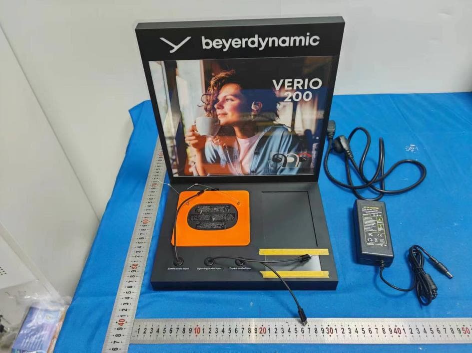
2BG2G-ADSBYG01
Jun 20, 2024Audio display stand
Equipment Class
DSS - Part 15 Spread Spectrum Transmitter