2BGAS-SA-DT21-0003DARK30 PTZ 640 Camera Remote Control
Sellmark Corporation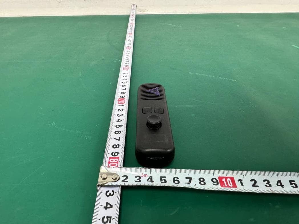
Click to zoom
Application Details
- Equipment Class
- DTS - Digital Transmission System
- Date of Grant
- Aug 06, 2024
- Application Purpose
- Original Equipment
- Date of Application
- Aug 02, 2024
- Equipment Note
- DARK30 PTZ 640 Camera Remote Control
- Frequency Range
- 2402.00000000 - 2480.00000000
- Company
- Sellmark Corporation
- Country
- United States
Documents & Files
Document Text
Text extracted from the exhibit documents filed with the FCC. Open a document above to read the original.
Users Manual
DT27000 WWW.DARK30.COM Dark 30 is a provider of advanced imaging technology for the outdoor community. Dedicated to innovation and excellence, Dark 30 delivers cutting-edge solutions designed to meet the diverse needs of professionals across various industries. © Sellmark Corporation, all rights reserved DEFIANCE The Dark 30 Defiance is an innovative PTZ vehicle-mounted thermal camera for mobile scouting. Eliminate the need for handheld observation and overcome the limitations of thermal-blocking windshield and window glass with this roof-mounted camera, providing a full 360° scan from an elevated vantage point. Mounted atop your vehicle, the Defiance offers a broader, clearer view compared to handheld or gun-mounted scanning. Its versatile mounting options—magnets, suction cups, or direct screws—ensure compatibility with any vehicle, with all hardware included. The 360-degree rotation and integrated directional indicator make it effortless to track and pinpoint targets. VEHICLE-MOUNTED THERMAL CAMERA • Variable Speed Remote Control • Sleep Mode • Return To Home Function • High Resolution 640x480 thermal imaging • Infinite 360° Panning • Low Latency HDMI compatible Wired Screen • App Control on the Dark 30 App • Versatile Mounting Options: (Permanent bolts, suction cups, or 100lb pull magnets.) • Water Resistant • 2in Riser • Base Kit • Remote • 10in Screen FEATURES ADDITIONAL ACCESSORIES 1 Type of sensorThermal sensor Sensor resolution, pixels 640x480 Display typeHDMI or app to external display Lens diameter, mm32 Display resolutionVarious Digital video recording 640x480 @60fps Maximum memory card4 to 512 (Class10 rec) Pixel size(μm)17x17 Spectral range8 - 14μm Detector NEDT (30Hz, 300K, F/1) (mK) <30 WIFIYe s Color palettes5 Lens material Germanium Digital zoom1-8x Field of View (degrees, Horizontal, Vertical and Diagnoal) 20 / 15 / 25 Power Supply12v DC Battery typeN/A for unit 2x AAA for Remote External power supplyCar cigarette power, 12VDC Ports1 TF card slot, 2 HDMI ports, 2 DC ports Water resistanceIP66 Pan angleContinuous 360 Tilt angleStraight downward to 45 degrees above horizontal Detection range (yd/m)1,258 / 1150 Body materialaluminum Operating temperature range-4°F to 122°F Dimensions in/mm6.65 / 169 x 7.68 / 195 x 7.8 / 198 Weight oz/g111 / 3150 Prop 65 / ROHS / CE / WEE, HDMI, FCC Yes - TBD specific / Yes / Yes / Yes Digital zoom1-8x Field of View (degrees, Hori- zontal) 20 Field of View (degrees, Vertical)15 Field of View (degrees, Diagonal)25 TECHNICAL SPECIFICATIONS 2 Q F R D E C H A DIAGRAM: 3 L. Display Suction Cup Mount M. Display Bar Clamp Mount N. ¼-20 Coupler O. Adjustable Arm for Mounts P. Base Cover Q. Power Splitter R. Camera Base S. 12v Power Port T. HDMI Port U. Camera Lock Ring V. TF Camera slot W. AAA Batteries V K L N U J I G W B S T P A. Camera B. Screen C. HDMI Cable D. Camera Power Cable (Longer 12v with Barrel Connector) E. Display Power Cable (Shorter 12v with Barrel Connector) F. Remote G. Magnetic Feet H. Suction Cup Feet I. M8 with 40mm length direct mounting bolts J. Direct Mounting Nuts K. Nut Driver M O O Start by removing the camera (A), display screen (B), HDMI cable (C), both power cables (D, E), remote (F), and the mounting option of your choice (bolt [I], magnetic feet [G], or suction cup feet [H]) inside. UNBOXING 4 T. HDMI Port U. Camera Lock Ring V. TF Camera slot W. AAA Batteries Attach your preferred mounting option (G, H, or I) to the base of the camera (A). Insert the four feet/mounting bolts into the base from below and secure them with nuts (J) on top. Use the included nut driver (K) to tighten the bolts. When using the suction cups, clean the surface they will be attached to and ensure it is smooth and does not have any holes, or the suction cups may not work properly. The suction cups can be cleaned with soap and warm water to remove any dirt or debris that may have adhered to the sticky side. DO NOT attach these to damaged painted surfaces, as they may remove the paint. 1. Remove all Magnetic Feet and mounting nuts from the case. 2. Align the Magnetic Feet so that the bolt goes through one of the mounting holes on the base. 3. Place a nut on top of the bolt and use the Nut Driver (K) to tighten the nut onto the Foot. 4. Repeat for the remaining 3 feet. 5. Clean the vehicle roof of any debris. 6. Place the camera with its feet flat on top of the roof. 7. Attach the camera's HDMI and Power Cables as described in the “Connecting the Cables” section. ASSEMBLING THE BASE: MOUNTING WITH MAGNETIC FEET 5 6 MOUNTING WITH SUCTION CUP FEET 1. Remove all suction cup feet and mounting nuts from the case. 2. Align the suction cup feet so that the bolt goes through one of the mounting holes on the base. 3. Place a nut on top of the bolt and use Nut Driver (K) to tighten the nut onto the foot. 4. Repeat steps 2 and 3 for the remaining 3 feet. 5. Clean the vehicle roof of any debris. 6. Place the camera with its feet flat on the roof. Make sure the levers on the feet are in the up and released position. 7. Once all feet are flat on the roof, pull the tab down on the foot to secure it. 8. Attach the cameras HDMI and Power Cables as described in the “Connecting the Cables” section. 7 1. Remove all mounting bolts and nuts from the case. 2. Align the bolts so that they go through the mounting holes on the base as well as the mounting holes in whatever you are mounting to (consult an expert if doing any modification to your vehicle). 3. Place a nut on top of the bolt and use the Nut Driver (K) to tighten the nut onto the foot. 4. Repeat steps 2 and 3 for the remaining 3 feet. 5. Attach the camera’s HDMI and Power Cables as described in the “Connecting the Cables” section. MOUNTING WITH BOLTS 8 REMOVING THE CAMERA FROM THE BASE (OPTIONAL): The camera can be removed from the base by twisting the lock ring counterclockwise until it is free and lifting the camera away from the base. The camera may require some force to remove due to the water sealing r…
Text truncated - open the document above for the full version.
External Photos
External Photos M/N: DT27000.01 External Photos M/N: DT27000.01 External Photos M/N: DT27000.01 External Photos M/N: DT27000.01
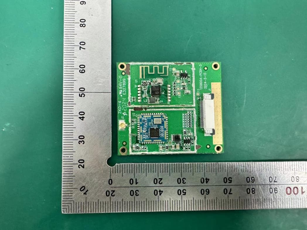
Internal Photos
Internal Photos M/N: DT27000.01 Bluetooth Antenna Internal Photos M/N: DT27000.01 Internal Photos M/N: DT27000.01 Internal Photos M/N: DT27000.01
RF Exposure Info
Page 1 of 3 Report No. ESTE-R2407168 FCC RF EXPOSURE REPORT Sellmark Corporation DARK30 PTZ 640 Camera Remote Control Model Number: DT27000.01 FCC ID: 2BGAS-SA-DT21-0003 Applicant: Sellmark Corporation Address: 2201 Heritage Parkway, Mansfield, Texas 76063, United States Prepared By: EST Technology Co., Ltd. Chilingxiang, Qishantou, Santun, Houjie, Dongguan, Guangdong, China Tel: 86-769-83081888-808 Report Number: ESTE-R2407168 Date of Test: Jun. 19, 2024~ Jul. 22, 2024 Date of Report: Jul. 23, 2024 Page 2 of 3 Report No. ESTE-R2407168 1. Applicable Standards FCC Part 2(Section 2.1093) FCC KDB 447498 D04 Interim General RF Exposure Guidance v01 2. Exposure Evaluation of Portable or Mobile Devices Human exposure to RF emissions from portable devices (47 CFR §2.1093), as defined by the FCC, must be evaluated with respect to the FCC-adopted limits for SAR. Evaluation of mobile devices, as defined by the FCC, may also be performed with respect to SAR limits, but in such cases it is usually simpler and more cost-effective to evaluate compliance with respect to field strength or power density limits. For certain devices that are designed to be used in both mobile and portable configurations similar to those described in 47 CFR §2.1091(d)(4), such as certain desktop phones and wireless modem modules, compliance for mobile configurations is also satisfied when the same device is evaluated for SAR compliance in portable configurations. The test exclusions are applicable only when the minimum test separation distance is ≤ 50 mm and for transmission frequencies between 300 MHz and 6 GHz. When the minimum test separation distance is < 5 mm, a distance of 5 mm is applied to determine SAR test exclusion. Page 3 of 3 Report No. ESTE-R2407168 3. Evaluation Results Mode Frequency (MHz) Peak output Power (dBm) Antenna Gain (dBi) effective radiated power (dBm) Target power (dBm) Max. Target power (mW) SAR Test Exemption Limit (mW) BLE 1M 2402 2.94 2.4 3.19 3±1 2.512 2.72 2441 2.86 2.4 3.11 3±1 2.512 2.72 2480 2.94 2.4 3.19 3±1 2.512 2.72 Note: 1. Limited=3060*(0.5/20)^x, x=-log(60/(3060*√f)). 2. We choose f=2.48GHz (Highest frequency operate at bluetooth) to calculate MPE limit as higher frequency will have lower MPE limits. 3. SAR Test Exclusion Thresholds is 2.72mW for separation distance 5mm. Therefore, SAR test is not required. End of Test Report
Test Report
Page 1 of 55 Report No.ESTE-R2407167 FCC PART 15C TEST REPORT FOR CERTIFICATION On Behalf of Sellmark Corporation DARK30 PTZ 640 Camera Remote Control Model Number: DT27000.01 FCC ID: 2BGAS-SA-DT21-0003 Applicant : Sellmark Corporation Address: 2201 Heritage Parkway, Mansfield, Texas 76063, United States Prepared By: EST Technology Co., Ltd. Chilingxiang, Qishantou, Santun, Houjie, Dongguan, Guangdong, China Tel: 86-769-83081888-808 Report Number: ESTE-R2407167 Date of Test: Jun. 19, 2024~ Jul. 22, 2024 Date of Report: Jul. 23, 2024 Page 2 of 55 Report No.ESTE-R2407167 TABLE OF CONTENTS Description Page TEST REPORT VERIFICATION .......................................................................................................... 3 1. GENERAL INFORMATION ................................................................................................................... 5 1.1. Description of Device (EUT) ............................................................................................................ 5 1.2. Antenna Information ......................................................................................................................... 5 1.3. Information of RF Cable ................................................................................................................... 5 2. SUMMARY OF TEST ........................................................................................................................... 6 2.1. Summary of test result ..................................................................................................................... 6 2.2. Test Facilities ..................................................................................................................................... 7 2.3. Measurement uncertainty ................................................................................................................ 8 2.4. Assistant equipment used for test .................................................................................................. 8 2.5. Block Diagram ................................................................................................................................... 8 2.6. Test Mode .......................................................................................................................................... 9 2.7. Power Setting of Test Software ...................................................................................................... 9 2.8. Duty Cycle .......................................................................................................................................... 9 2.9. Channel List ..................................................................................................................................... 10 2.10. Test Equipment List ...................................................................................................................... 11 3. 6DB BANDWIDTH ............................................................................................................................ 12 3.1. Limit ................................................................................................................................................... 12 3.2. Test Setup ........................................................................................................................................ 12 3.3. Spectrum Analyzer Setting ............................................................................................................ 12 3.4. Test Procedure ................................................................................................................................ 12 3.5. Test Result ....................................................................................................................................... 12 4. MAXIMUM PEAK OUTPUT POWER .................................................................................................. 13 4.1. Limit ................................................................................................................................................... 13 4.2. Test Setup ........................................................................................................................................ 13 4.3. Spectrum Analyzer Setting ............................................................................................................ 13 4.4. Test Procedure ................................................................................................................................ 13 4.5. Test Result ....................................................................................................................................... 13 5. POWER SPECTRAL DENSITY .......................................................................................................... 14 5.1. Limit ................................................................................................................................................... 14 5.2. Test Setup ........................................................................................................................................ 14 5.3. Spectrum Analyzer Setting ............................................................................................................ 14 5.4. Test Procedure ................................................................................................................................ 14 5.5. Test Result ....................................................................................................................................... 14 6. CONDUCTED BAND EDGE .............................................................................................................. 15 6.1. Limit ................................................................................................................................................... 15 6.2. Test Se…
Text truncated - open the document above for the full version.
Test Report
` 保存期:永久 EVS-FR-RD-20-A 物料承认书 文件编号:RD-ACK-RC___-___版本:___ ComponentItem物料编号 PartName物料名称 BT Antenna Specification物料规格 BT Antenna L=80MM MHF, YJT01.182.023.302A 有害环境物质管理要求 (依照最新法规公布实施的 管控标椎和清单执行) ■ RoHS 2.0(2011/65/EU) □ REACH □ CP65 (加州65) □CPSIA □ASTM F963□EN71 □MSDS □TSCA □其它: Datasheet物料规格书 COMPANY APPROVED 本厂承认 Approved By批准: Checked By审核: Compile By编制: Data日期: 年 月 日 Data日期: 年 月 日Data日期: 年 月 日 SUPPLIER CONFIRMED 供应商确认 有害环境物质测试报告编号: A2230400553101001E,EKR23700180,SHAEC24000428805 A2230400553101002E,(8824)054-0003,SHAEC23019069715 A2240168137102001,A2240187677101001,ETR23701480 A2230601245104001C,A2230643348101001 CANEC24000977302,SHAEC23021627701 供应商签名/公章: 变更履历表 版本 变更内容 工程师确认 审核/日期 批准/日期 1 首次发行 邓磊 2024/6/3 2024/6/3 2 3 4 供应商对已承认物料做出工程变更或原料变更时,必须要本公司重新承认 承认书项目表 NO . 内容 (Contents) 页数 (Number of Page) 页码 (Page Code) 1 承认书封面(Spec Cover) 11 承认书封面(p) 2 承认书项目表(Spec Item ) 12 3 工程成品图(Drawing) 13 4 天线规格(Antenna Specification) 14 5 S参数测试(S Parameter ) 15 6 无源测试(Passive Test ) 26 ~ 7 7 方向图(Radiation Pattern ) 18 8 天线装配图(Antenna Profile) 39 ~ 11 9 材质证明(Mt ilC tifi t) 5812 699 材质证明(Material Certificate ) 5812 ~ 69 10 RoHS报告(RoHS Test Report ) **** 11N/AN/AN/A add:东莞市长安镇沙头社区木鱼路59号元富工业区Tel:0769-82586086 Fax:0769-82586086 12--- 13--- 天线规格 Antenna Specification Electrical Properties Frequency 2.4-2.5GHz Impedance50 Ohm Nominal V.S.W.R2.0 Max Gain 2.4 dBi RadiationOmni-directional PolarizationLinear Physical Properties Connector 3代IPEX Cable TypeO.D.0.81mm Cable Length80mm Cable ColorBlack add:东莞市长安镇沙头社区木鱼路59号元富工业区Tel:0769-82586086 Fax:0769-82586086 Operating Temp.-40 ~ +85 ̊C Storage Temp / Humidity 25±5 ̊C / <70% Antenna Performance TestAntenna Performance Te s t AgilentAgilent E5071B S11 ParameterParameter Test // BT AntennaAntenna add:东莞市长安镇沙头社区木鱼路59号元富工业区Tel:0769-82586086 Fax:0769-82586086 Antenna Passive TestAntenna Passive Te s t Z Y X X Z Y add:东莞市长安镇沙头社区木鱼路59号元富工业区Tel:0769-82586086 Fax:0769-82586086 Passive Test For BT Antenna FreqEffiEffiGain (MHz)(%)(dB)(dBi) 2400 44.9-3.52.0 2410 45.7-3.41.9 2420 45.5-3.41.8 2430 45.8-3.41.8 2440 45.8-3.41.7 2450 48.9-3.12.1 2460 47.3-3.31.6 2470 48.9-3.12.2 2480 47.4-3.22.0 add:东莞市长安镇沙头社区木鱼路59号元富工业区Tel:0769-82586086 Fax:0769-82586086 2490 48.3-3.22.4 2500 45.7-3.42.1 Radiation Pattern For BT Antenna 2400MHz 2450MHz 2500MHz add:东莞市长安镇沙头社区木鱼路59号元富工业区Tel:0769-82586086 Fax:0769-82586086 DeviceDevice add:东莞市长安镇沙头社区木鱼路59号元富工业区Tel:0769-82586086 Fax:0769-82586086 BT Antenna add:东莞市长安镇沙头社区木鱼路59号元富工业区Tel:0769-82586086 Fax:0769-82586086 BT Antenna add:东莞市长安镇沙头社区木鱼路59号元富工业区Tel:0769-82586086 Fax:0769-82586086 PSM-800FSDM-A/SMH-800 , 安 全 資 料 表 1 版權 2021-01-10 First, chemical products and materials for business Chemical name: PSM-800FSDM-A/SMH-800 liquid solid plate ink Other names: Use and restricted use of construction: flexible printed circuit board (PI/Cu), hand machine roof board Name, address and address of the creator, entrant or supplier: Creator: Yueli Reachability Co., Ltd. Address: No.22 Jingjian Fourth Road, Guanyin District, Taoyuan City: 886-3- 4836651 Urgent/true: 886-3-4836651, true: 886-3-4837487 Second, the hazard identification of resources and materials Hazard classification of chemical products: Health and environmental hazards: Acute toxicity (swallowing) 4, rot/skin irritation 2, heavy weight/eye irritation 2, skin Pass sensitive substance first, carcinogenic substance second, and hazardous substance second (acute toxicity). Indication of content: S y m b o l n u m b e r : Warning language: Warning hazard warning interest: Harmful to swallow Cause skin irritation Causing severe eye irritation may cause skin hypersensitivity and suspected carcinogenesis Toxic to aquatic organisms Hazard prevention measures: Put the container in a place with good ventilation far away from the high temperature Do not eat or drink when using Remove the blindfold/face mask immediately when your clothes are contaminated If you touch your eyes, wash them with plenty of water immediately, and then ask the mud to wear suitable gloves Do not inhale gas/gas/steam gas/gas before use Place it in the upper lock Do not place until you know all safety precautions Avoid releasing release in the environment Other hazards:- III. Composition identification of PSM-800FSDM-A/SMH-800 , 安 全 資 料 表 2 版權 2021-01-10 capital mixture: Liquid solid plate ink PSM-800FSDM-A/SMH-800 Chemical geology: Chinese and English names of hazardous components Register number of Chemical Digest Service (CAS No.) Degree or degree (percentage of components) Oxygen acrylate oligmer Epoxy acrylate oligmer 28064-14-4 50% Silicon dioxide Fused silica 7631-86-9 13% Aromatic solution 64742-94-5 4% PSM-800FSDM-A/SMH-800 , 安 全 資 料 表 3 版權 2021-01-10 Methyl dipropylene glycol 34590-94-8 4% Carbon black 1333-86-4 3.5% BaSO4 sulfate 13462-86-7 24% Photoinitiator and the others 5495-84-1 1.5% Fourth, first aid measures First aid methods for the same road: Inhalation: 1. Take self-protection measures before rescue. 2. Remove pollution sources or move patients to new places. 3. If a patient stops breathing, artificial respiration should be given immediately by the person who has been adalmed. If the heart stops, cardiopulmonary resuscitation should be given. When the patient inhales and swallows toxic substances, mouth-to-mouth artificial respiration should be used directly, and pocket masks and other medical equipment should be used for artificial respiration. 4. Maintain the patient's safety and normal temperature. 6. Treat the cure quickly. Pi Mo: Wash the contaminated area with harmonious water for at least 20 minutes, and remove contaminated clothes, shoes and leather products before water. Eye touching: Immediately open the eyelids and wash the contaminated eyes with water for at least 20 minutes, and immediately take care of them. Intake: 1. If the patient will be frustrated, or has been frustrated, he can feed anything. 2. It can induce vomiting and give 240-300ml of water. 3. If you vomit spontaneously, rinse your mo…
Text truncated - open the document above for the full version.
Test Setup Photos
Radiated emission test: Below 1GHz Radiated emission test: Above 1GHz
Contact Information
Applicant
Jonathan Horton(Design and Development Director)
Test Firm
EST Technology Co., Ltd.Iceman Hu
[email protected]+86 0769-83081888
Technical Specifications
| # | Rule Parts | Frequency Range | Power Output |
|---|---|---|---|
| 1 | 15C | 2.40 GHz - 2.48 GHz | 1.97 mW |
Other Applications from Sellmark Corporation
2BGAS-DT27000
Aug 06, 2024DARK30 PTZ 640 Camera
Equipment Class
DTS - Digital Transmission System