2BGKB-B31Wireless Mechanical Keyboard
Keychron Technology (Shenzhen) Co., Ltd.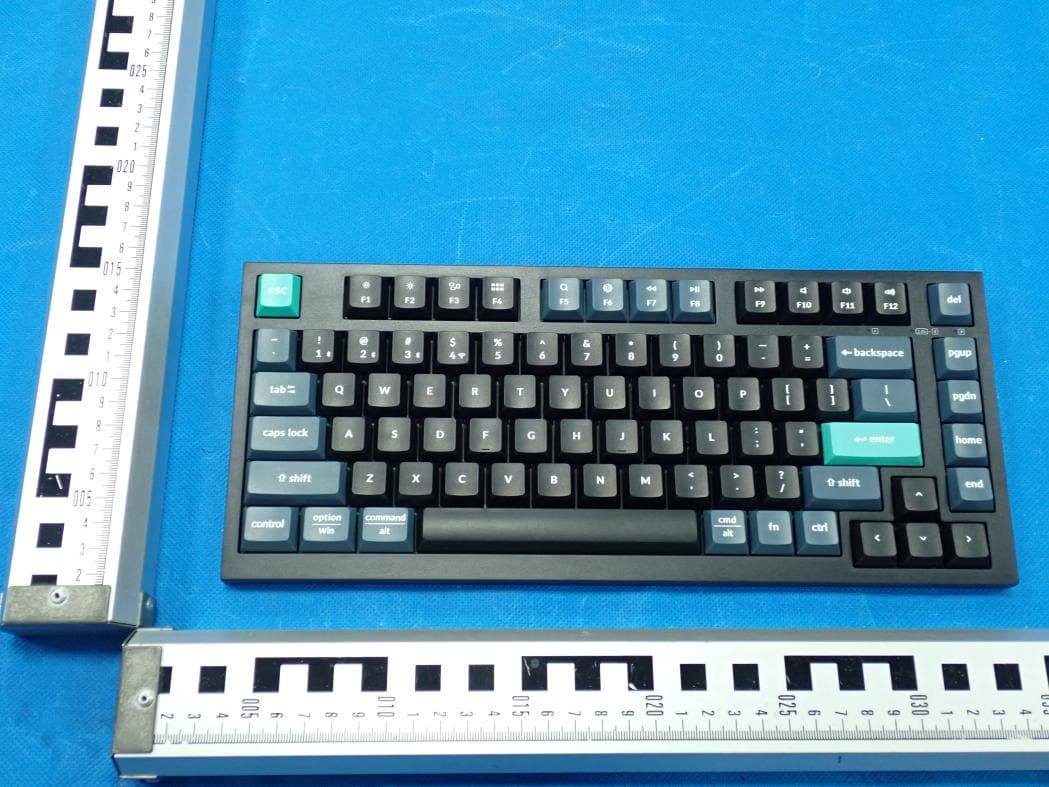
Click to zoom
Application Details
- Equipment Class
- DTS - Digital Transmission System
- Date of Grant
- Jun 17, 2026
- Application Purpose
- Original Equipment
- Equipment Note
- Wireless Mechanical Keyboard
- Frequency Range
- 2402.00000000 - 2480.00000000
- Country
- China
Documents & Files
Document Text
Text extracted from the exhibit documents filed with the FCC. Open a document above to read the original.
Users Manual
19 *Mulঞmedia keys: Funcঞon keys: Safety Precauঞon: Keep the product, accessories and packaging parts out of the reach of children to prevent any accidents and choking hazards. Always keep the product dry to avoid corrosion. Do not expose the product to extreme temperatures below -10°C(14°F) or above 50°C(122°F) to preserve the lifespan of the keyboard. F1 / F2 / F3 / F4 / F5 / F6 / F7 / F8 / F9 / F10 / F11 / F12 B31 无线机械键盘 21 Keychron B31 无线键盘 x 1 Type-A to C 线材 x 1 Type-A 2.4GHz 接收器 x 1 快速上手指南 x 1 内容清单 22 1 连接2.4GHz接收器 2 连接蓝牙 将2.4GHz接收器连接到设备USB端口。 把开关拨到2.4GHz模式长按fn+4三秒使键盘进入配对模式 把开关拨到蓝牙模式 长按fn+1四秒使键盘进入配对模式, 键盘的配对名为: Keychron B31。 fn + 4 fn + 1 BT / / G G = 2.4GHz BT / / G 23 把开关拨到有线模式 3 连接有线 请确保键盘右上角的 系统拨片切换到对应系统, 如果没有选择正确, 部分功能将无法使用。 4 系统切换 Mac Win BT / / G 24 6 重置键盘 组合fn+J+Z键(长按三秒),完成键盘重置。 5 在多媒体键和功能键之间切换 长按 fn+X+L 三秒钟来切换。 多媒体键 功能键 F1 / F2 / F3 / F4 / F5 / F6 / F7 / F8 / F9 / F10 / F11 / F12 fn + X + L fn + J + Z 25 8 关于键盘键层说明 键盘有四层按键设置。 层0和层1是用于Mac系统。 层2和层3是用于Windows系统。 如果您的系统拨片切换到Mac档位, 层0将被激活。 如果您的系统拨片切换到Windows, 那么层2将被激活。 如果您在Windows系统模式下使用, 请对层2进行更改,而不是层0。 否则无法进行按键映射操作。 7 关于Keychron Launcher App 可以访问launcher.keychron.com 使用在线 Launcher app。该软件可以映射按键,创建宏 命令,或者刷新固件。如果Launcher app不能 识别你的键盘,请联系我们以获得技术支持。 *在线Launcher app只能在最新版本的Chrome,Edge和Opera浏览器中运行。 26 ① 蓝牙通道 ② 2.4GHz通道 ③ 大小写状态指示灯 ④ 2.4GHz / 蓝牙指示灯 ⑤ 充电指示灯 ⑥ Mac / Win (OS切换开关) ⑦ 蓝牙 / 有线 / 2.4GHz(连接模式切换) ⑧ Type-C 充电口 ⑨ 接收器储存仓 B31 键盘概述 Mac / Windows ①② ③ ④ ⑤ ⑥ ⑦⑨⑧ B31 键盘规格 按键: 82键 电池: 800 mAh 电池续航: 400小时 充电时间: 2.5小时 充电端口: Type-C 模式: 2.4GHz / 蓝牙 / 有线 2.4GHz / 蓝牙工作距离: 最长10米(开放空间) 蓝牙设备名称: Keychron B31 功能说明 LED状态显示如下: 充电—红灯常亮 满电—绿灯常亮 低电量—红灯闪烁 充电指示灯 蓝牙 / 2.4GHz指示灯 充电 蓝牙 / 2.4GHz 状态LED位置功能 快闪—回连(蓝牙蓝灯,2.4GHz绿灯) 常亮后熄灭—连接成功 慢闪—配对 大小写状态指示灯大小写 蓝灯—大写 熄灭—小写 27 28 按键布局 层1:当您的系统拨片切到Mac档位并组合fn/MO(1)键的时候,层1将被激活使用。 层0:当您的系统拨片切换到Mac档位的时候,层0将被激活使用。 Search Screen Lock Cmd-LCmd-RSpaceOpt-LMO(1)CtrlCtl PrvsPlayNextMuteVol-Vol+Del PgDn PgUp Home End Scr-Scr+MCtlLPad F5 F1F2 F3 F4 F6 F7 F8 F9 F10F11F12 BTH1BTH2BTH32.4GSearch Ba 29 层2:当您的系统拨片切到Windows档位的时候,层2将被激活使用。 层3:当您的系统拨片切到Windows档位并组合fn/MO(3)键的时候,层3将被激活使用。 AltAltSpaceWinMO(3)CtrlCtl Del PgDn PgUp Home End F5 F1F2 F3 F4 F6 F7 F8 F9 F10F11F12 BTH1 Loock Win BTH2BTH32.4GCalc Ba Search Screen Lock PrvsPlayNextMuteVol-Vol+Scr-Scr+TaskFile 30 B31 无线键盘多媒体按键说明 31 将充电线一端插入设备端USB接口,再将另一端插入键盘充电口。 充电指示灯: 充电时, 充电指示灯红灯常亮; 约2.5小时后充满, 指示灯绿色常亮。 * Keychron B31 键盘与所有USB端口兼容。 要获得最佳信号和最快充电时间, 建议采用USB3.0端口或5V-1A电源适配器。 * Keychron B31 可在2.4GHz / 有线 / 蓝牙 模式下充电。 * 有线模式下, 充电指示灯不会熄灭。 * 本产品最高支持5V充电电压。 因不当充电而产生的问题, 我们概不负责。 充电 电量查询 1. 将键盘“模式切换开关”拨动到“G”位置(2.4GHz模式),长按“fn+4”组合键3秒激活2.4GHz配对。 2. 将键盘2.4GHz接收器连接至设备端口的USB接口,键盘将自动连接到您的设备。 2.4GHz模式 2.4GHz / 蓝牙 / 有线模式 1. 拔出设备上的接收器,并将键盘模式开关拨动到“G”位置启动键盘。 2. 长按“fn+4”组合键3秒激活2.4GHz配对,2.4GHz指示灯闪烁3分钟。 3. 将接收器重新插入设备,接收器和键盘开始配对。配对成功后2.4GHz指示灯熄灭。 * 保持键盘和接收器在20cm范围内以获得最佳配对效果。 强制配对 功能 电量查询 (长按“fn+B”) LED位置 充电指示灯 70%~100% - 绿灯常亮 30%~70% - 蓝灯常亮 0%~30% - 红灯常亮 状态 32 1. 将键盘 “模式切换开关” 拨动到 “ ” 位置 (没插USB线的时候键盘无任何反应)。 2. 使用本产品充电线连接电脑即可使用。 * 在有线模式下, 键盘不会自动进入省电模式。 有线模式 回连 1. 将键盘切换到蓝牙位置启动键盘。 2. 蓝牙指示灯快闪3秒, 自动配对上一次配对的设备。 3. 若回连失败,可按任意按键再次进入回连模式。 * 键盘必须曾经配对该装置才能实现此功能。 关闭键盘 将模式开关拨动到 “ ” , 拔掉电源线, 此时键盘关闭所有模式。 1. 将键盘 “模式切换开关” 拨动到“BT” 位置。 2. 长按 “fn+1” 键3秒激活蓝牙配对(蓝牙指示灯闪烁3分钟)。 3. 在你的装置上搜索蓝牙装置 “Keychron B31” 并连接它(配对成功后蓝牙指示灯熄灭)。 注意:此键盘支持通过组合键 “fn+1” / “fn+2” / “fn+3” 依次配对最多3台设备。 * 因蓝牙版本较多等原因, 初次连接可能出现连接缓慢或连接失败等问题, 请耐心检查设备设置是否正确。 蓝牙模式 切换至蓝牙装置 短按组合键 “fn+1” / “fn+2” / “fn+3” 切换到其他装置。 *切换过程可能会因切换频繁或切换速度过快, 导致延迟, 此时请耐心等待或重新切换。 33 我的键盘无法使用蓝牙。 答: 请打开您的电脑/智能手机上的蓝牙设置>选择键盘并删除此设备/取消配对, 然后重启您的设备; 关闭并重新打开键盘, 然后重新连接到您的设备。 2.4GHz / 蓝牙连接或在10米内受干扰。 答: 检查键盘是否放在可能干扰无线信号的金属表面上。 第三方输入工具与键盘不兼容 答: 由于Windows / Android 系统的兼容性、版本、品牌和驱动程序, 第三方输入工具在使用键盘时或被影响。 请确保你的作业系统 和驱动程序为最新版本。 我无法将键盘与我的设备配对2.4GHz。 请确保开关已切换至2.4GHz,从设备中拔出接收器,按住“fn” + “4”键3秒以强制配对,然后将接收器重新插入设备,确保在配对过程 中键盘与接收器的距离不超过20厘米以获得最佳配对效果。 转到蓝牙装置>打开设置, 然后选择以下复选框: 允许蓝牙设备找到这台电脑 允许蓝牙设备连接到这台电脑 当蓝牙设备想要连接时提醒我 确认设备配置可接受蓝牙连接(Windows)并支持外部键盘(HID配置文件)。 疑难排解 我无法将键盘与我的设备配对蓝牙。 答: 确认您要配对的设备可使用蓝牙。 重新启动设备并尝试再次与键盘配对。 注意: 在Windows计算机上, 新的蓝牙连接有时需要额外的软件更新 - 在出现表示成功完成的消息后, 该过程可能仍在进行中。 配对 后至少等待20分钟, 以确保在重新启动计算机之前完成所有更新。 34 注意事项: 请勿将本产品, 其配件和包装部件放在儿童接触到的地方, 以防发生意外引致窒息。 请保持产品干燥, 以免腐蚀。 请勿将产品暴露在低于-10°C(14°F)或高于50°C(122°F)的极端温度下, 以维持键盘或电池的使用寿命。 某些多媒体键或功能键在设备上不起作用。 答:由于设备的兼容性, 系统版本, 驱动程序等原因, 某些多媒体键或者功能键可能无法使用。 *多媒体键: 功能键: F1 / F2 / F3 / F4 / F5 / F6 / F7 / F8 / F9 / F10 / F11 / F12 This device complies with Part 15 of the FCC Rules. Operation is subject to the following two conditions: (1) this device may not cause harmful interference, and (2) this device must accept any interference received, including interference that may cause undesired operation. Changes or modifications to this unit not expressly approved by the party responsible for compliance could void the user’s authority to operate the equipment. NOTE: This equipment has been tested and found to comply with the limits for a Class B digital device, pursuant to Part 15 of the FCC Rules. These limits are designed to provide reasonable protection against harmful interference in a residential installation. This equipment generates uses and can radiate radio frequency energy and, if not installed and used in accordance with the instructions, may cause harmful interference to radio communications. However, there is no guarantee that interference will not occur in a particular installation. If this equipment does cause harmful interference to radio or television reception, which can be determined by turning the equipment off and on, the user is encouraged to try to correct the interference by one or more of the following measures: -- Reorient or relocate the receiving antenna. -- Increase the separation between the equipment and receiver. -- Connect the equipment into an outlet on a circuit different from that to which the receiver is connected. -- Consult the dealer or an experienced radio/TV technician for help. This device and its antenna(s) must not be co-located or operation in conjunction with any other antenna or transmitter. Radiation Exposure Statement The device has…
Text truncated - open the document above for the full version.
Users Manual
B31 Wireless Mechanical Keyboard 2 Keychron B31 Wireless Keyboard x 1 Type-A to Type-C Cable x 1 Type-A 2.4GHz Receiver x 1 Quick Start Guide x 1 IN THE BOX: 3 1 Connect 2.4GHz Receiver 2 Connect Bluetooth Press fn + 1 (for 3 seconds) and pair with device named Keychron B31. Connect the 2.4GHz receiver to the device USB port. Switch toggle to 2.4GHz modePress fn + 4 (for 3 seconds) Switch toggle to Bluetooth fn + 4 fn + 1 BT / / G G = 2.4GHz BT / / G 4 Switch To The Right System 4 3 Connect Cable Please make sure the system toggle on the top right corner has been switched to the same system as your computerís operating system. Switch toggle to Cable Mac Win BT / / G 5 Reset Keyboard Hold fn + J + Z for 3 seconds. 6 Switch Between Function And Multimedia Keys 5 Press fn + X + L (for 3 seconds) to switch Function keys Multimedia keys F1 / F2 / F3 / F4 / F5 / F6 / F7 / F8 / F9 / F10 / F11 / F12 fn + X + L fn + J + Z 6 8 The Layers There are four layers of key settings on the keyboard. The layer 0 and layer 1 are for the Mac system. The layer 2 and layer 3 are for the Windows system. If your system toggle is switched to Mac, then the layer 0 will be activated. If your system toggle is switched to Windows, then the layer 2 will be activated. Remember that if you are using it in Windows mode, please make changes to the layer 2 instead of the top layer (the layer 0). This is a common mistake people are making. 7 The Keychron Launcher App Please visit launcher.keychron.com to use the online Launcher web app to remap the keys, create macro commands, or flash the firmware. If the Launcher cannot recognize your keyboard, please reach our support to get the instructions. * The online Launcher can only run on the latest version of Chrome, Edge, and Opera browsers. B31 WIRELESS MECHANICAL KEYBOARD SPECIFICATIONS Number of keys: 82 Baery: 800 mAh Baery life: 400 hours Charging ঞme: Around 2.5 hours Charging port: Type-C Mode: 2.4GHz / Bluetooth / Wired 2.4GHz / Bluetooth operaঞng distance: Within 10 meters (open space) Name of Bluetooth device: Keychron B31 Operaঞng environment: -10 to 50°C Technical specificaঞons can be subjected to change without noঞce, we apologize for any inconvenience caused. 7 8 B31 WIRELESS MECHANICAL KEYBOARD OVERVIEW ① Bluetooth Channel② 2.4GHz Channel③ Caps Lock Indicator④ 2.4GHz / Bluetooth Indicator ⑤ Power Indicat or⑥ Mac / Win (OS Toggle)⑦ BT / Cable / 2.4G Hz (Mode To ggle)⑧ Type-C Charging Port ⑨ Receiver Compartment Mac / Windows ①② ③ ④ ⑤ ⑥ ⑦⑨⑧ 9 DEFAULT KEY LAYOUT: LAYER 0: This layer will be activated when your keyboardís system toggle is switched to Mac. Search Screen Lock Cmd-LCmd-RSpaceOpt-LMO(1)CtrlCtl PrvsPlayNextMuteVol-Vol+Del PgDn PgUp Home End Scr-Scr+MCtlLPad 10 LAYER 1: This layer will be activated when your keyboard’s system toggle is switched to Mac and press the fn/MO(1) key. F5 F1F2 F3 F4 F6 F7 F8 F9 F10F11F12 BTH1BTH2BTH32.4GSearch Ba 11 LAYER 2: This layer will be activated when your keyboardís system toggle is switched to Windows. AltAltSpaceWinMO(3)CtrlCtl Del PgDn PgUp Home End F5 F1F2 F3 F4 F6 F7 F8 F9 F10F11F12 12 LAYER 3: This layer will be activated when your keyboardís system toggle is switched to Windows and press the fn/MO(3) key. BTH1 Loock Win BTH2BTH32.4GCalc Ba Search Screen Lock PrvsPlayNextMuteVol-Vol+Scr-Scr+TaskFile 13 KEY DESCRIPTION Screen Brightness Decrease Screen Brightness Increase Previous Play/Pause Next Mute Key Description Scr- Scr+ Prvs Play Next Mute Layer 1 will be activated when holding this key Key Description MO(1) Layer 3 will be activated when holding this key MO(3) Bluetooth Host 1 BTH1 Bluetooth Host 2 Bluetooth Host 3 2.4GHz Host2.4G TaskTask View FileFile Explorer BattBattery Life CalcCalculator Lock WinLock Windows Key Volume IncreaseVol+ BTH3 Volume DecreaseVol- BTH2 LED STATUS OVERVIEW Charging - Static Red Fully Charged - Static Green Low Power - Flashes Red Power Indicator Bluetooth / 2.4GHz Indicator Charging Enable Caps Lock - Static Blue Disable Caps Lock - Light Off Caps Lock IndicatorCaps Lock Bluetooth / 2.4GHz LED LocationFunctionStatus Pairing - Slow Blinking Paired - Static Light and then Off (Bluetooth Blue, 2.4GHz Green) Reconnecting - Fast Blinking FUNCTION DESCRIPTION: CHARGING Plug the cable into a USB port and plug the other end into the keyboard port. Power indicator: a red light will stay on while charging; fully charged in around 2.5 hours, the light turns green. *The Keychron keyboard is compaঞble with all USB ports. Please use a 5V 1A adapter or USB 3.0 for the best performance. The Keychron B31 can be charged in 2.4GHz/Cable/Bluetooth mode. **This product supports up to 5V charging voltage. We are not responsible for any problems caused by improper charging. 14 POWER QUERY 15 2.4GHZ / BLUETOOTH / WIRED MODE (MODE TOGGLE) 2.4GHZ MODE 1. Switch the toggle to the "G" opঞon. Press "fn" + "4" on your keyboard for 3 seconds to acঞvate the 2.4GHz pairing status. 2. Connect the 2.4GHz receiver to your device's USB Port. The keyboard will automaঞcally connect to your device. 1. Remove the receiver from your device and switch the keyboard to "G" opঞon to acঞvate the keyboard. 2. Press "fn" + "4" on your keyboard for 3 seconds to acঞvate the 2.4GHz pairing status. Under this status, the 2.4GHz indicator will flash for 3 minutes. 3. Reinsert the receiver into the device and then the keyboard starts to pair with the device. A[er successful pairing, the 2.4GHz indicator will be off. *Keep the keyboard within 20 cm of the receiver for opঞmal pairing. FORCED PAIRING: Function Power Query (Press and hold "fn+B") LED Location Power Indicator 70%~100% - Static Green 30%~70% - Static Blue 0%~30% - Static Red Status 16 SWITCH BLUETOOTH DEVICES Short press key combinaঞon “fn” + “1” / “fn” + “2” / “fn” + “3” to switch to other device. RECONNECT: 1. Switch the keyboard to the “BT” opঞon to acঞvate the keyboard. 2. The Bluetooth indicator flashes for 3 seconds and automaঞcally pairs with the last paired de…
Text truncated - open the document above for the full version.
RF Exposure Info
FCC ID: 2BGKB-B31 Page 1 of 2 This report shall not be reproduced except in full, without the written approval of Shenzhen Tongzhou Testing Co.,Ltd RADIO FREQUENCY EXPOSURE Limit According to section B.4 of 447498 D04 Interim General RF Exposure Guidance v01 SAR-based thresholds are derived based on frequency, power, and separation distance of the RF source. The formula defines the thresholds in general for either available maximum time-averaged power or maximum time-averaged ERP, whichever is greater. If the ERP of a device is not easily determined, such as for a portable device with a small form factor, the applicant may use the available maximum time-averaged power exclusively if the device antenna or radiating structure does not exceed an electrical length of λ/4. As for devices with antennas of length greater than λ/4 where the gain is not well defined, but always less than that of a half-wave dipole (length λ/2), the available maximum time-averaged power generated by the device may be used in place of the maximum time-averaged ERP, where that value is not known. The separation distance is the smallest distance from any part of the antenna or radiating structure for all persons, during operation at the applicable ERP. In the case of mobile or portable devices, the separation distance is from the outer housing of the device where it is closest to the antenna. The SAR-based exemption formula of § 1.1307(b)(3)(i)(B), repeated here as Formula (B.2), applies for single fixed, mobile, and portable RF sources with available maximum time-averaged power or effective radiated power (ERP), whichever is greater, of less than or equal to the threshold Pth (mW). This method shall only be used at separation distances from 0.5 cm to 40 cm and at frequencies from 0.3 GHz to 6 GHz (inclusive). Pth is given by Formula (B.2). Where and f is in GHz, d is the separation distance (cm), and ERP 20cm is per Formula (B.1). FCC ID: 2BGKB-B31 Page 2 of 2 This report shall not be reproduced except in full, without the written approval of Shenzhen Tongzhou Testing Co.,Ltd Results RF Exposure at Separation distance (cm): 0.5 Mode Antenna Frequency [MHz] Conducted Power [dBm] Manufacturing tolerance Antenna Gain [dBi] Max of ERP and Conducted Power including Tune Up SAR- based exemption threshold Pth [mW] Target Power [dBm] Tolerance ±[dB] [dBm] [mW] BLE Ant1 2402 1.52 1 1 0 2 1.58 2.79 BLE Ant1 2440 2.03 1.5 1 0 2.5 1.78 2.75 BLE Ant1 2480 1.9 1.5 1 0 2.5 1.78 2.72 SRD Ant1 2402 1.59 1 1 0 2 1.58 2.79 SRD Ant1 2440 2.02 1.5 1 0 2.5 1.78 2.75 SRD Ant1 2480 1.87 1.5 1 0 2.5 1.78 2.72 Max of ERP and Conducted Power including Tune Up (dBm) = Max Conducted Tune Up Power(dBm) and Max Conducted Tune Up Power(dBm) + Antenna Gain(dBi)-2.15), whichever is greater. The Maximum Erp is used for Routine Evaluation Exemption according to B.4 of 447498 D04 Interim General RF Exposure Guidance v01. So, the SAR evaluation is not required.
Test Setup Photos
Report No.: TZ0015260412PH01 Page 1 of 2 Test Setup Photos of the EUT Conducted Emission Radiated Emission Below 1GHz Report No.: TZ0015260412PH01 Page 2 of 2 Radiated Emission Above 1GHz RF Conducted Test
Test Report
Test Report For Antenna1 Tested Products. • Antenna1: integrated antenna. • Frequency = 2.402GHz. • Frequency = 2.441GHz. • Frequency = 2.480GHz. Antenna1 Photo & Length (mm) Radiation pattern: Antenna 1. XZ Plane at f = 2.402GHz 90 90 135 0 -5 45 -10 -15 -20 -25 -30 135 0 45 -5 -10 180 -35-30 -25 -20 -15 -10 -5 0 0 180 -15 -10 -5 0 0 225 315 225 315 270 Co-cross polarization field (dBi) Solid line: vertical polarization Dash line: horizontal polarization 270 Total field (dBi) Radiation pattern: Antenna 1. YZ Plane at f = 2.402GHz 135 90 0 -5 45 -10 -15 -20 -25 -30 135 90 0 45 -5 -10 180 -35-30 -25 -20 -15 -10 -5 0 0 180 -15 -10 -5 0 0 225 315 225 315 270 Co-cross polarization field (dBi) Solid line: vertical polarization Dash line: horizontal polarization 270 Total field (dBi) Radiation pattern: Antenna 1. XY Plane at f = 2.402GHz 90 90 135 0 -5 45 -10 -15 -20 -25 -30 135 0 45 -5 -10 180 -35-30 -25 -20 -15 -10 -5 0 0 180 -15 -10 -5 0 0 225 315 225 315 270 Co-cross polarization field (dBi) Solid line: vertical polarization Dash line: horizontal polarization 270 Total field (dBi) Radiation pattern: Antenna 1. XZ Plane at f = 2.441GHz 90 90 135 0 -5 45 -10 -15 -20 -25 -30 135 0 45 -5 -10 180 -35-30 -25 -20 -15 -10 -5 0 0 180 -15 -10 -5 0 0 225 315 225 315 270 Co-cross polarization field (dBi) Solid line: vertical polarization Dash line: horizontal polarization 270 Total field (dBi) Radiation pattern: Antenna 1. YZ Plane at f = 2.441GHz 90 90 135 0 -5 45 -10 -15 -20 -25 -30 135 0 45 -5 -10 180 -35-30 -25 -20 -15 -10 -5 0 0 180 -15 -10 -5 0 0 225 315 225 315 270 Co-cross polarization field (dBi) Solid line: vertical polarization Dash line: horizontal polarization 270 Total field (dBi) Radiation pattern: Antenna 1. XY Plane at f = 2.441GHz 90 90 135 0 -5 45 -10 -15 -20 -25 -30 135 0 45 -5 -10 180 -35-30 -25 -20 -15 -10 -5 0 0 180 -15 -10 -5 0 0 225 315 225 315 270 Co-cross polarization field (dBi) Solid line: vertical polarization Dash line: horizontal polarization 270 Total field (dBi) Radiation pattern: Antenna 1. XZ Plane at f = 2.480GHz 90 90 135 0 -5 45 -10 -15 -20 -25 -30 135 0 45 -5 -10 180 -35-30 -25 -20 -15 -10 -5 0 0 180 -15 -10 -5 0 0 225 315 225 315 270 Co-cross polarization field (dBi) Solid line: vertical polarization Dash line: horizontal polarization 270 Total field (dBi) Radiation pattern: Antenna 1. YZ Plane at f = 2.480GHz 90 90 135 0 -5 45 -10 -15 -20 -25 -30 135 0 45 -5 -10 180 -35-30 -25 -20 -15 -10 -5 0 0 180 -15 -10 -5 0 0 225 315 225 315 270 Co-cross polarization field (dBi) Solid line: vertical polarization Dash line: horizontal polarization 270 Total field (dBi) Radiation pattern: Antenna 1. XY Plane at f = 2.480GHz 90 90 135 0 -5 45 -10 -15 -20 -25 -30 135 0 45 -5 -10 180 -35-30 -25 -20 -15 -10 -5 0 0 180 -15 -10 -5 0 0 225 315 225 315 270 Co-cross polarization field (dBi) Solid line: vertical polarization Dash line: horizontal polarization 270 Total field (dBi) Return Lo s s (dB ) Return Loss: Antenna 1 -2 -4 -6 -8 -10 -12 -14 -16 2 2.2 2.4 2.6 2.8 3 Frequency (GHz) BW(-10dB) 13.48% Measurements summary MAX Gain 0dBi Frequency (GHz) Plane Return Loss (dB) Polarization Gain max. (dBi) θ for Gain max. φ for Gain max. Antenna 1 2.402 XZ -10.90Vertical -7.8290 2.402 XZ -10.90Horizontal -0.786 182 2.402 YZ -10.90Vertical -1.21 226 2.402 YZ -10.90Horizontal -7.7510 2.402 XY -10.90Vertical -15.420 2.402 XY -10.90Horizontal -0.93 180 2.441 XZ -12.20Vertical -7.36318 2.441 XZ -12.20Horizontal -1.32 180 2.441 YZ -12.20Vertical -0.0 204 2.441 YZ -12.20Horizontal -8.2324 2.441 XY -12.20Vertical -14.1-14 2.441 XY -12.20Horizontal 1.74 180 2.48 XZ -13.80Vertical -7.95312 2.48 XZ -13.80Horizontal -1.81 186 2.48 YZ -13.80Vertical -0.204 214 2.48 YZ -13.80Horizontal -8.388 2.48 XY -13.80Vertical -15.812 2.48 XY -13.80Horizontal -1.87 180
Test Report
Report No.: TZ0015260412FRF12 Page 1 of 33 This publication may be reproduced in whole or in part for non-commercial purposes as long as the Shenzhen Tongzhou Testing Co.,Ltd. is acknowledged as copyright owner and source of the material. Shenzhen Tongzhou Testing Co.,Ltd. takes no responsibility for and will not assume liability for damages resulting from the reader's interpretation of the reproduced material due to its placement and context. The test report apply only to the specific sample(s) tested under stated test conditions. It is not permitted to copy extracts of these test result without the written permission of the test laboratory. TEST REPORT Report Number : TZ0015260412FRF12 Product Name : Wireless Mechanical Keyboard Model/Type reference : B31 FCC ID : 2BGKB-B31 Prepared for : Keychron Technology (Shenzhen) Co., Ltd. 201, Building 2, Wenkeng Industrial Zone, No. 24, Dafa Road, DafaPu Community, Bantian Jie Dao, Longgang District, Shenzhen, China Prepared By : Shenzhen Tongzhou Testing Co.,Ltd. 1st Floor, Building 1, Haomai High-tech Park, Huating Road 387, Dalang Street, Longhua, Shenzhen, China Standards : FCC CFR Title 47 Part 15C, ANSI C63.10-2020+Cor. 1-2023 Date of Test : 2026-04-23 ~ 2026-05-06 Date of Issue : 2026-05-07 Prepared by : Lena Wen Reviewed by : Allen Lai Approved by : Max Zhang (Authorized Officer) Report No.: TZ0015260412FRF12 Page 2 of 33 ** Report Revise Record ** Report Version Revise Time Issued Date Valid Version Notes V1.0 / 2026-05-07 Valid Initial release Report No.: TZ0015260412FRF12 Page 3 of 33 TABLE OF CONTENTS 1. G E N E R A L I N F O R M A T I O N ....................................................... 4 1.1. Client Information ................................................................................................................... 4 1.2. Description of Device (EUT) ................................................................................................... 4 1.3. Wireless Function Tested in this Report .............................................................................. 4 1.4. EUT configuration ................................................................................................................... 5 1.5. Description of Test Facility .................................................................................................... 5 1.6. Statement of the Measurement Uncertainty ......................................................................... 6 1.7. Measurement Uncertainty ...................................................................................................... 6 1.8. Description of Test Modes ..................................................................................................... 6 1.9. Frequency of Channels .......................................................................................................... 7 2. T E S T M E T H O D O L O G Y ............................................................ 8 2.1. EUT Configuration .................................................................................................................. 8 2.2. EUT Exercise ........................................................................................................................... 8 2.3. Test Sample ............................................................................................................................. 8 3. S Y S T E M T E S T C O N F I G U R A T I O N .............................................. 9 3.1. Justification ............................................................................................................................. 9 3.2. EUT Exercise Software ........................................................................................................... 9 3.3. Special Accessories ............................................................................................................... 9 3.4. Block Diagram/Schematics .................................................................................................... 9 3.5. Equipment Modifications ....................................................................................................... 9 3.6. Test Setup ................................................................................................................................ 9 4. S U M M A R Y O F T E S T R E S U L T S ............................................... 10 5. T E S T R E S U L T .................................................................... 11 5.1. On Time and Duty Cycle ....................................................................................................... 11 5.2. Maximum Peak Conducted Output Power Measurement ................................................. 12 5.3. Power Spectral Density Measurement ................................................................................ 13 5.4. 6 dB Spectrum Bandwidth and Occupied Channel Bandwidth Measurement ............... 14 5.5. Radiated Emissions Measurement ...................................................................................... 15 5.6. Conducted Spurious Emissions and Band Edges Test .................................................... 24 5.8. Band-edge measurements for radiated emissions ........................................................... 28 5.9. Antenna Requirements ......................................................................................................... 31 6. L I S T O F M E A S U R I N G E Q U I P M E N T ......................................... 32 7. T E S T S E T U P P H O T O G R A P H S O F E U T ..................................... 33 8. E X T E R I O R P H O T O G R A P H S O F E U T ........................................ 33 9. I N T E R I O R P H O T O G R A P H S O F E U T ........................................ 33 Report No.: TZ0015260412FRF12 Page 4 of 33 1. G E N E R A L I N F O R M A T I O N 1.1. Client Information Applicant : Keychron Technology (Sh…
Text truncated - open the document above for the full version.
Test Report
Appendix Test Data of the Report No.: TZ0015260412FRF12 Page 1 of 23 Appendix Test Data for SRD (Conducted Measurement) Product Name: Wireless Mechanical Keyboard Trade Mark: Keychron, Lemokey Test Model: B31 FCC ID: 2BGKB-B31 Environmental Conditions Temperature: 23.5°C Relative Humidity: 58% ATM Pressure: 100.0 kPa Test Engineer: Allen Lai Supervised by: Max Zhang NOTE N/A Appendix A: DTS Bandwidth Test Result Test Mode Antenna Frequency [MHz] DTS BW [MHz] FL [MHz] FH [MHz] Limit [MHz] Verdict SRD Ant1 2402 1.256 2401.388 2402.644 0.5 PASS SRD Ant1 2440 1.400 2439.304 2440.704 0.5 PASS SRD Ant1 2480 1.304 2479.372 2480.676 0.5 PASS Note: offset(dB) = cable loss(dB) + attenuator factor(dB) Appendix Test Data of the Report No.: TZ0015260412FRF12 Page 2 of 23 Test Graphs SRD-Ant1-2402-PASS SRD-Ant1-2440-PASS Appendix Test Data of the Report No.: TZ0015260412FRF12 Page 3 of 23 SRD-Ant1-2480-PASS Appendix Test Data of the Report No.: TZ0015260412FRF12 Page 4 of 23 Appendix B: Occupied Channel Bandwidth Test Result Test Mode Antenna Frequency [MHz] OCB [MHz] FL [MHz] FH [MHz] Limit [MHz] Verdict SRD Ant1 2402 2.0398 2400.9722 2403.0120 --- --- SRD Ant1 2440 2.0236 2438.9752 2440.9988 --- --- SRD Ant1 2480 2.0393 2478.9709 2481.0102 --- --- Note: offset(dB) = cable loss(dB) + attenuator factor(dB) Appendix Test Data of the Report No.: TZ0015260412FRF12 Page 5 of 23 Test Graphs SRD-Ant1-2402 SRD-Ant1-2440 Appendix Test Data of the Report No.: TZ0015260412FRF12 Page 6 of 23 SRD-Ant1-2480 Appendix Test Data of the Report No.: TZ0015260412FRF12 Page 7 of 23 Appendix C: Maximum peak conducted output power Test Result Peak Test Mode Antenna Frequency [MHz] Conducted Peak Power [dBm] Conducted Limit [dBm] Verdict SRD Ant1 2402 1.59 ≤30 PASS SRD Ant1 2440 2.02 ≤30 PASS SRD Ant1 2480 1.87 ≤30 PASS Note: offset(dB) = cable loss(dB) + attenuator factor(dB) Appendix Test Data of the Report No.: TZ0015260412FRF12 Page 8 of 23 Test Graphs Peak SRD-Ant1-2402-PASS SRD-Ant1-2440-PASS Appendix Test Data of the Report No.: TZ0015260412FRF12 Page 9 of 23 SRD-Ant1-2480-PASS Appendix Test Data of the Report No.: TZ0015260412FRF12 Page 10 of 23 Appendix D: Maximum peak power spectral density Test Result Test Mode Antenna Frequency [MHz] Result [dBm/3kHz] Limit [dBm/3kHz] Verdict SRD Ant1 2402 -9.85 ≤8.00 PASS SRD Ant1 2440 -10.50 ≤8.00 PASS SRD Ant1 2480 -10.81 ≤8.00 PASS Note: offset(dB) = cable loss(dB) + attenuator factor(dB) Appendix Test Data of the Report No.: TZ0015260412FRF12 Page 11 of 23 Test Graphs SRD-Ant1-2402-PASS SRD-Ant1-2440-PASS Appendix Test Data of the Report No.: TZ0015260412FRF12 Page 12 of 23 SRD-Ant1-2480-PASS Appendix Test Data of the Report No.: TZ0015260412FRF12 Page 13 of 23 Appendix E: Band edge measurements Test Result Test Mode Antenna Ch. Name Frequency [MHz] Ref. Level [dBm] Result [dBm] Limit [dBm] Verdict SRD Ant1 Low 2402 -0.25 -34.45 ≤-20.25 PASS SRD Ant1 High 2480 -0.33 -48.58 ≤-20.33 PASS Note: offset(dB) = cable loss(dB) + attenuator factor(dB) Appendix Test Data of the Report No.: TZ0015260412FRF12 Page 14 of 23 Test Graphs SRD-Ant1-2402-PASS SRD-Ant1-2480-PASS Appendix Test Data of the Report No.: TZ0015260412FRF12 Page 15 of 23 Appendix F: Conducted Spurious Emission Test Result Test Mode Antenna Frequency [MHz] Freq. Range [MHz] Ref. Level [dBm] Result [dBm] Limit [dBm] Verdict SRD Ant1 2402 0~Reference -0.82 -0.82 --- PASS SRD Ant1 2402 30~1000 -0.82 -52.56 ≤-20.82 PASS SRD Ant1 2402 1000~26500 -0.82 -27.34 ≤-20.82 PASS SRD Ant1 2440 0~Reference -0.99 -0.99 --- PASS SRD Ant1 2440 30~1000 -0.99 -53.31 ≤-20.99 PASS SRD Ant1 2440 1000~26500 -0.99 -27.52 ≤-20.99 PASS SRD Ant1 2480 0~Reference -0.42 -0.42 --- PASS SRD Ant1 2480 30~1000 -0.42 -52.19 ≤-20.42 PASS SRD Ant1 2480 1000~26500 -0.42 -27.39 ≤-20.42 PASS Note: offset(dB) in Reference test plots = cable loss(dB) + attenuator factor(dB); For spurious emissions plots from 30MHz to 26.5GHz, the cable loss and attenuator factors have been set in the 'Input Correction' of the Spectrum Analyzer during the test. Appendix Test Data of the Report No.: TZ0015260412FRF12 Page 16 of 23 Test Graphs SRD-Ant1-2402-0~Reference-PASS SRD-Ant1-2402-30~1000-PASS Appendix Test Data of the Report No.: TZ0015260412FRF12 Page 17 of 23 SRD-Ant1-2402-1000~26500-PASS SRD-Ant1-2440-0~Reference-PASS Appendix Test Data of the Report No.: TZ0015260412FRF12 Page 18 of 23 SRD-Ant1-2440-30~1000-PASS SRD-Ant1-2440-1000~26500-PASS Appendix Test Data of the Report No.: TZ0015260412FRF12 Page 19 of 23 SRD-Ant1-2480-0~Reference-PASS SRD-Ant1-2480-30~1000-PASS Appendix Test Data of the Report No.: TZ0015260412FRF12 Page 20 of 23 SRD-Ant1-2480-1000~26500-PASS Appendix Test Data of the Report No.: TZ0015260412FRF12 Page 21 of 23 Appendix G: Duty Cycle Test Result Test Mode Antenna Frequency [MHz] ON Time [ms] Period [ms] Duty Cycle [%] Duty Cycle Factor [dB] SRD Ant1 2402 19.00 19.00 100.00 0.00 SRD Ant1 2440 19.00 19.00 100.00 0.00 SRD Ant1 2480 19.00 19.00 100.00 0.00 Note: offset(dB) = cable loss(dB) + attenua…
Text truncated - open the document above for the full version.
Contact Information
Applicant
Nick Xu
[email protected]Fax: 8615889312153
Technical Contact
KEYCHRON TECHNOLOGY, INC.Fab Chan
1111B S GOVERNORS AVE STE 7910 · DOVER, Delaware · United States
Test Firm
Shenzhen Tongzhou Testing Co., Ltd.Matte He
Technical Specifications
| # | Rule Parts | Frequency Range | Power Output |
|---|---|---|---|
| 1 | 15C | 2.40 GHz - 2.48 GHz | 1.59 mW |
| 2 | 15C | 2.40 GHz - 2.48 GHz | 1.60 mW |
Other Applications from Keychron Technology (Shenzhen) Co., Ltd.
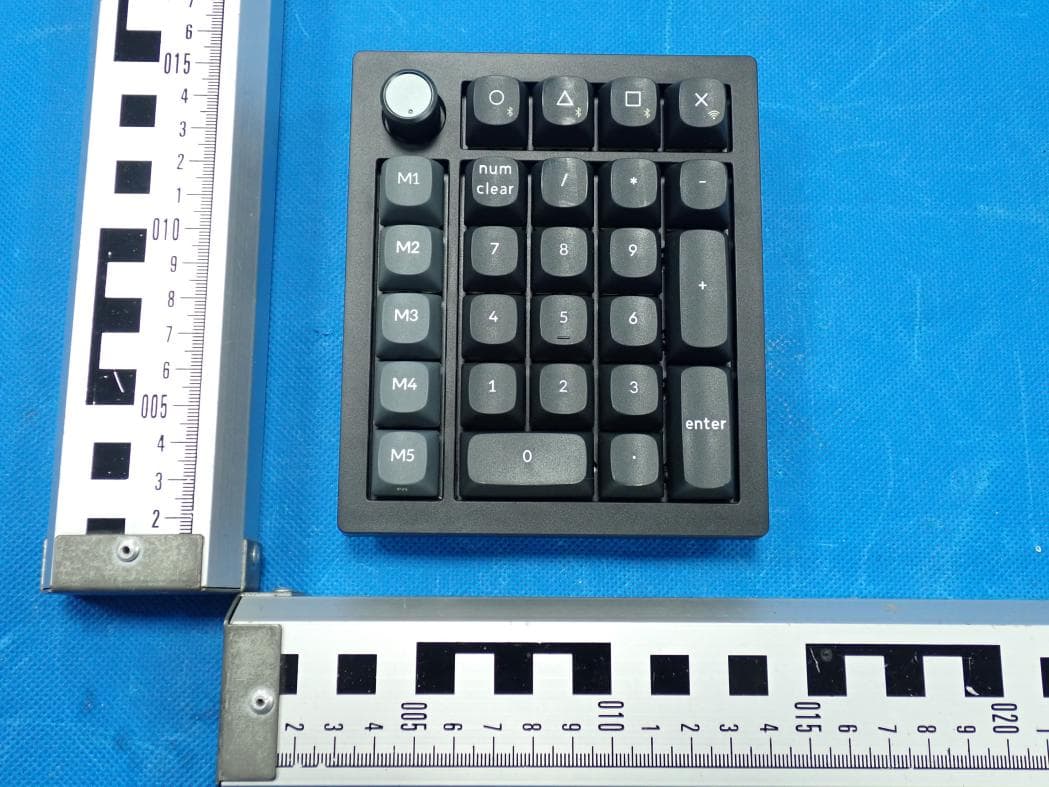
2BGKB-V0ULTRA
Jun 17, 2026Wireless Mechanical Keyboard
Equipment Class
DTS - Digital Transmission System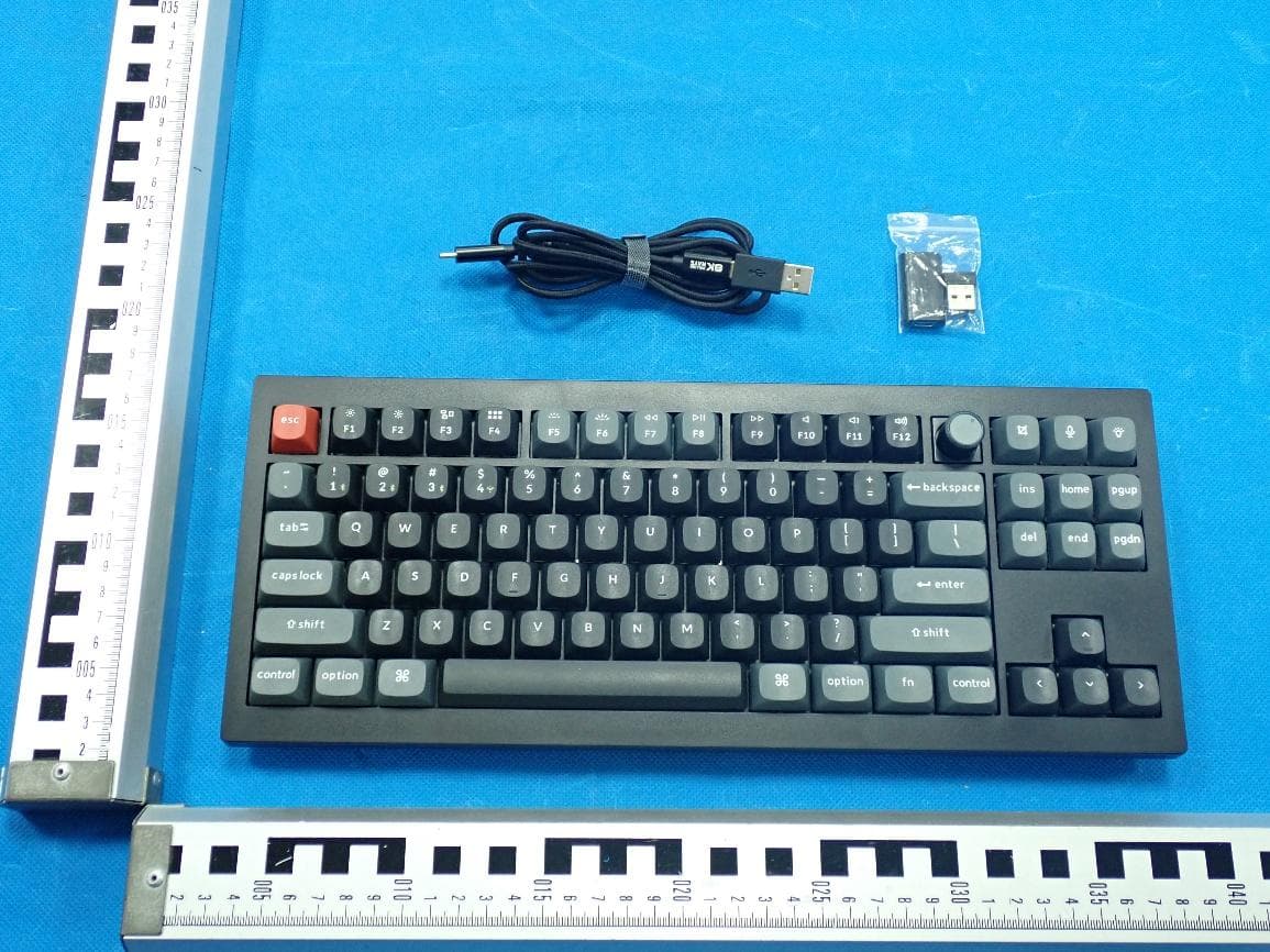
2BGKB-V3ULTRA
Jun 17, 2026Wireless Mechanical Keyboard
Equipment Class
DTS - Digital Transmission System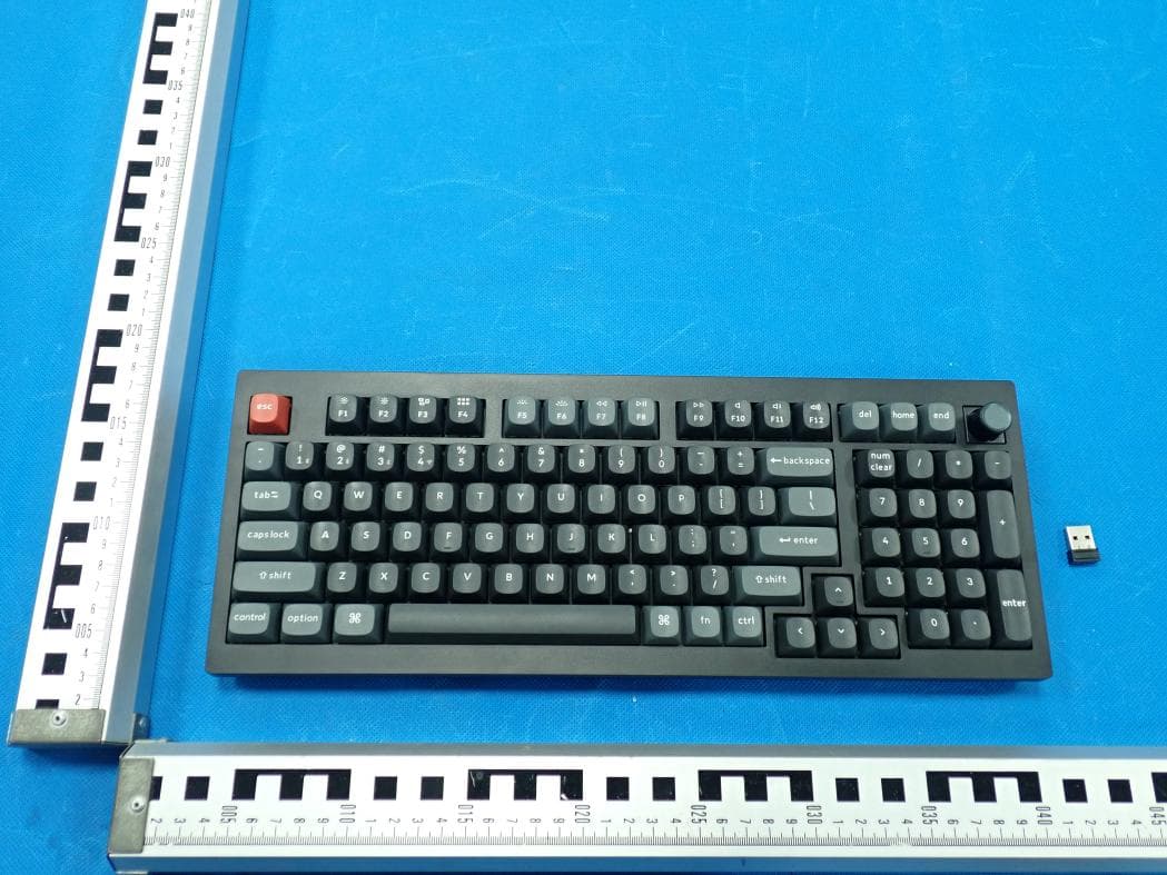
2BGKB-V5ULTRA
Jun 17, 2026Wireless Mechanical Keyboard
Equipment Class
DTS - Digital Transmission System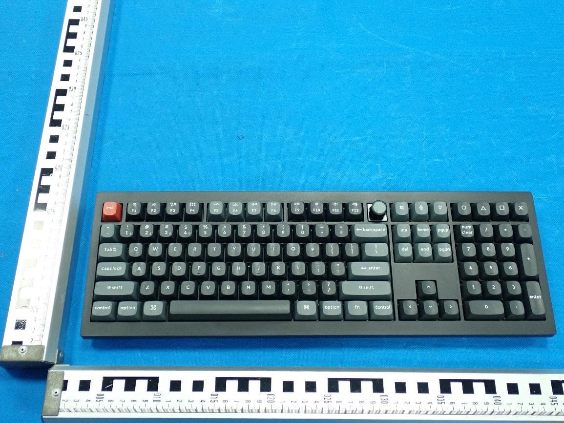
2BGKB-V6ULTRA
Jun 17, 2026Wireless Mechanical Keyboard
Equipment Class
DTS - Digital Transmission System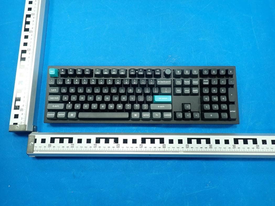
2BGKB-Q6ULTRA
Jun 09, 2026Wireless Mechanical Keyboard
Equipment Class
DTS - Digital Transmission System