2BLTR-TH2000Dual Band Mobile Radio
Quanzhou RadioBoss Technology Co., Ltd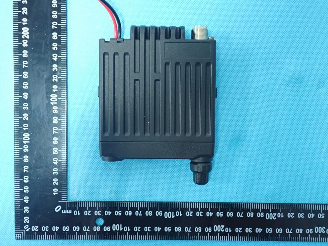
Click to zoom
Application Details
- Equipment Class
- CSR - Scanning Receiver
- Date of Grant
- Jun 29, 2026
- Application Purpose
- Original Equipment
- Equipment Note
- Dual Band Mobile Radio
- Frequency Range
- 136.00000000 - 174.00000000
- Country
- China
Documents & Files
Document Text
Text extracted from the exhibit documents filed with the FCC. Open a document above to read the original.
Users Manual
our Though friendly design for user,this transceiver is technically complicated and some features maybe be new to you.Considering this manual to be a personal tutorial from the designers,allow the manual to guide you through the learning process now,then act as a reference in the coming years. Please observe the following precautions to prevent fire, personal injury, or transceiverdamage: Do not attempt to configure your transceiver while driving,it is dangerous. This transceiver is designed for a 12V and 24V DC power supply. Do not place the transceiver in excessively dusty, humid or wet areas, nor unstablesurfaces. Please keep it away from interferential devices (suchas TV, generator etc.) Do not expose the transceiver to long periods of directsunlight nor place it close to heating applianc- es. If an abnormal odor or smoke is detected comingfrom the transceiver, turn OFF the power immedi- ately.Contact local service station or your dealer. Do not transmit with high output power for extended periods; the transceiver mayoverheat. Please contact the local authorized dealer if you have any questions.We are not responsible for any typographical errors that may by in this manual.Standard accessories may change without noice, getting your understanding for any inconveniences. When programming the transceiver,need the factory initial data firstly, and then rewrite the frequency and signaling etc.Otherwise errors may occur because of different frequency band etc. Precautions 1313 Supplied Accessories Installation Functions and features Getting Acquainted Basic operation Menu function instruction Signalings Specifications CONTENTS 01 03 10 11 18 25 29 38 Professional FM Transceiver Supplied Accessories User’s Manual Professional FM Transceiver Installation User’s Manual 02 HardwareFuse*2User's Manual*1 *1*1 123 456 789 A ENT B VFO C MR D A/B # UP 0 MUTE * DWN *1 *1 Panel bracket Microphone bracket*1 Supplied Accessories/Optional Accessories Supplied Accessories 04 05 Mobile installation To install the transceiver,select a safe,convenient location inside your vehicle thatminimizes danger to your passengers and yourself while the vehicle is in motion.Considerinstalling the unit at an appropriate position so that knees or legs will not strike it duringsudden braking of your vehicle.Try to pick a well ventilated location that is shielded fromdirect sunlight. 1.Install the mounting bracket in the vehicle using the supplied self-tapping screws(4pcs)and flat washers(4pcs). 2.Position the transceiver,hen insert and tighten the supplied hexagon SEMS screws. ■ Double check that all screws are tightened to prevent vehicle vibration from loosening the bracket or transceiver. ■ Determine the appropriate angle of the transceiver,using the screw hole positions on the side of the mounting bracket. DC Power Cable Connection NOTE:Locate the power input connector as close to the transceiver as possible. This transceiver is designed for a 12V and 24V DC power supply. Initial Installation Mobile Operation Car Battery DC Power Cable Mobile Radio +12V Ignition Switch LOCK ACC ON START 06 07 1.Route the DC power cable supplied with the transceiver directly to the vehicle's batteryterminals using the shortest path from the transceiver. ■ We recommend you do not use the cigarette lighter socket as some cigarette lighter sockets introduce an unacceptable voltage drop. ■ The entire length of the cable must be dressed so it is isolated from heat,moisture,and the engine secondary (high voltage)ignition system/cables.2.After installing cable,in order to avoid the risk of damp,please use heat-resistant tap totie together with fuse box.Don't forget to reinforce whole cable. The transceiver will return to its normal operation when the power is switched ON orrepeat above operation. Antenna Connection Before operating,installan efficient,well-tuned antenna.The success of your installationwill depend largely on the type of antenna andits correct installation.The transceiver cangive excellent results if the antenna system and its installation are given careful attention.Use a 50Ω impedance antenna and lowHoss coaxial feed-line that has a characteristicimpedance of 50Ω,to match the transceiver input impedance.Coupling the antenna tothe transceiver via feed-lines having an impedance other than 50*reduces the efficiencyof the antenna system and can cause interference to nearby broadcast television receivers,radio receivers,and other electronic equipment. NOTE:Transmitting without first connecting an antenna or other matched load may damagethe transceiver.Always connect the antenna tothe transceiver before transmitting. All fixed stations should be equipped with a lightning arrester to reduce the risk of fire,electric shock,and transceiver damage. The possible locations of antenna on a car are shown as following: 08 09 Accessories Connections External Speaker ■ If you plan to use an external speaker,choose a speaker with an impedance of 8Ω.Theexternal speaker jack accepts a 3.5 mm(1/8")mono (2-conductor)plug. NOTE:External speaker adopt double port BTL,please care about the connecting way.The speaker can not connect with the ground,otherwise the speaker will be fault.Thewrong connecting way as the follow- ing picture. Microphone ■ For voice communications,connect a microphone equipped with an 8-pin modular pluginto the modular socket on the front of the main unit.Press firmyly on the plug until thelocking tab clicks.At- tachthe supplied microphone hanger in an appropriate location usingthe screws included in the screw set. Professional FM Transceiver Getting Acquainted 10 Functions and features ■ Supports 12/24V voltage ■ Dual band,dual wait,dual standby,dual watch ■ Speaker gain ■ Mic Gain ■ Auto power off ■ DOT-MATRIXLCD Display ■ 200 channels ■ FM radio for 32 channels storage ■ Wide/Middle/Narrow bandwidth select ■ High/Middle/Low power select ■ Talk permit tone ■ Roger tone ■ Sub band tone ■ Remote stun/kill/activate ■ TOT ■ ANI ■…
Text truncated - open the document above for the full version.
Attestation Statements
Quanzhou RadioBoss Technology Co., Ltd Covered Equipment Certification Attestation Letter 6/26/2026 Federal Communications Commission Authorization and Evaluation Division 7435 Oakland Mills Road Columbia, MD 21046 USA ATTN.: Reviewing Engineer FCC ID: 2BLTR-TH2000 Quanzhou RadioBoss Technology Co., Ltd (“the applicant”) certifies that the equipment for which authorization is sought is not “covered” equipment prohibited from receiving an equipment authorization pursuant to section 2.903 of the FCC rules. Note: If the equipment for which the applicant seeks authorization is produced by any of the entities identified on the current Covered List, the applicant should include an explanation on why the equipment is not “covered” equipment. Quanzhou RadioBoss Technology Co., Ltd (“the applicant”) certifies that, as of the date of the filing of the application, the applicant is not identified on the Covered List (as a specifically named entity or any of its subsidiaries or affiliates) as an entity producing “covered” equipment. Quanzhou RadioBoss Technology Co., Ltd (“the applicant”) certifies that the equipment for which authorization is sought does not include cybersecurity or anti-virus software produced or provided by Kaspersky Lab, Inc. or any of its successors and assignees, including equipment with integrated Kaspersky Lab, Inc. (or any of its successors and assignees) cybersecurity or anti-virus software pursuant to DA-24-886 and KDB 986446 D01 Covered Equipment Guidance section B(2a). Signed: Printed name: Sophia Wong Title: General Manager Company Name: Quanzhou RadioBoss Technology Co., Ltd Date: 6/26/2026
Attestation Statements
The information provided in this letter is based on the referenced rule parts of Title 47 of the CFR as well as KDB 986446 D01. An expiration date for this letter does not exist. In case the U.S. agent changes, the grantee is obligated to notify the FCC within 30 days via the granting TCB. 48_[model] US_Agent_2.911(d)(7) - U, V05 Quanzhou RadioBoss Technology Co., Ltd No.8, Chuangzao Road Optoelectronics-information industry base, Nan'an Quanzhou, Fujian, China Federal Communications Commission Authorization and Evaluation Division Equipment Authorization Branch 7435 Oakland Mills Road Columbia, MD 21046 Date: Jun. 26, 26 U.S. Agent Designation Quanzhou RadioBoss Technology Co., Ltd acknowledges their consent for the following contact located in the United States to act as their agent for service of process for the equipment for which authorization is sought (FCC ID: 2BLTR-TH2000) Name and company of U.S. agent: GLOCERTS TECHNOLOGY INC Physical U.S. address of agent: 19784 SUNKISSED RIDGE DR, RIVERSIDE, CA 92507 FRN of U.S. agent: 0036339737 Email address of U.S. agent: [email protected] Telephone of U.S.agent: (626) 588-8039 GLOCERTS TECHNOLOGY INC acknowledges their obligation to accept service of process on behalf of Quanzhou RadioBoss Technology Co., Ltd. Quanzhou RadioBoss Technology Co., Ltd with the FRN [0036189447] accepts its obligation to maintain an agent for service of process in the United States for no less than 1 year after either the grantee has permanently terminated all marketing and importation of the applicable equipment within the U.S., or the conclusion of any Commission-related administrative or judicial proceeding involving the equipment, whichever is later. By signing this form, we confirm the above and that we are aware of the application requirements listed under § 2.911(d)(7). The information provided in this letter is based on the referenced rule parts of Title 47 of the CFR as well as KDB 986446 D01. An expiration date for this letter does not exist. In case the U.S. agent changes, the grantee is obligated to notify the FCC within 30 days via the granting TCB. Sincerely, Signature Signature Sophia Wong Huiying Fan General Manager Director Quanzhou RadioBoss Technology Co., Ltd GLOCERTS TECHNOLOGY INC
Cover Letter(s)
Quanzhou RadioBoss Technology Co., Ltd DATE: 6/26/2026 Federal Communications Commission Authorization & Evaluation Division 7345 Oakland Mills Road Columbia, Maryland 21046 Authority to Act as Agent On our behalf, I appoint Shenzhen Tongzhou Testing Co.,Ltd. (1st Floor, Building 1, Haomai High-tech Park, Huating Road 387, Dalang Street, Longhua, Shenzhen, China) to act as our agent in the preparation of this application for equipment certification. I certify that submitted documents properly describe the device or system for which equipment certification is sought. I also certify that each unit manufactured, imported or marketed, as defined in the Federal Communications Commission’s regulations will have affixed to it a label identical to that submitted for approval with this application. For instances where our authorized agent signs the application for certification on our behalf, I acknowledge that all responsibility for complying with the terms and conditions for certification, still resides with Quanzhou RadioBoss Technology Co., Ltd (No.8, Chuangzao Road, Optoelectronics-information industry base, Nan’an, Quanzhou, Fujian, China) <Signature> Name: Sophia Wong Title: General Manager Applicant Company: Quanzhou RadioBoss Technology Co., Ltd
Cover Letter(s)
Date: 6/26/2026 Federal Communications Commission Authorization & Evaluation Division 7345 Oakland Mills Road Columbia, Maryland 21046 RE: LETTER OF AGENT AUTHORIZATION To Whom It May Concern: We, the undersigned, hereby authorize Compliance Testing, LLC to act on our behalf in all matters relating to application for equipment authorization, including the signing of all documents relating to these matters. We also hereby certify that no party to the application authorized hereunder is subject to the denial of benefits, including FCC benefits, pursuant to Section 5301 of the Anti-Drug Abuse Act of 1988, 21 U.S.C.853(a). Sincerely, <Signature> Name: Sophia Wong Title: General Manager Company: Quanzhou RadioBoss Technology Co., Ltd
Cover Letter(s)
DATE: 6/26/2026 Equipment Autorisation Division Federal Communications Commission 7435 Oakland Mills Road Columbia, MD 21046 FCC ID: 2BLTR-TH2000 Product Name: Dual Band Mobile Radio Request for Confidentiality Pursuant to Sections 0.457 and 0.459 of the commission’s rules, we hereby request that the following documents be held confidential: (List here the documents for which you are seeking confidentiality – for example ...) • Schematics • Block diagram • Operation description • Part Lists These materials contain trade secrets and proprietary information and are not customarily released to the public. The public disclosure of this information might be harmful to the company and provide unjustified benefits to our competitors. <Signature> Name: Sophia Wong Title: General Manager Company: Quanzhou RadioBoss Technology Co., Ltd
Cover Letter(s)
Quanzhou RadioBoss Technology Co., Ltd No.8, Chuangzao Road, Optoelectronics-information industry base, Nan’an, Quanzhou, Fujian Date: 2026-06-26 Declaration Letter FEDERAL COMMUNICATIONS COMMISSION Authorization and Evaluation Division 7435 Oakland Mills Road Columbia, MD 21046 Subject: Declaration of compliance to the requirements of §15.121 FCC ID: 2BLTR-TH2000 Dear Sir/Madam, We declare that, this scanning receiver is incapable of operating (tuning), or readily being altered by the users to operate, within the frequency bands allocated to the Cellular Radiotelephone Service in part 22 of this chapter (cellular telephone bands). This device will not be able to receive transmissions in the cellular telephone bands by means of clipping the leads of, or installing, a simple component such as a diode, resistor or jumper wire; replacing a plug-in semiconductor chip; or programming a semiconductor chip using special access codes or an external device, such as a personal computer. This device is also incapable of converting digital cellular communication transmissions to analog voice audio. This device is designed so that the tuning, control and filtering circuitry is inaccessible. Any attempts to modify the equipment to receive transmissions from the Cellular Radiotelephone Service will render the receiver inoperable. This scanning receiver rejects any signals from the Cellular Radiotelephone Service frequency bands that are 38 dB or lower based upon a 12 dB SINAD measurement. We are aware that the modification of this device to receive transmissions from Cellular Radiotelephone Service frequency bands will be considered to constitute manufacture of such equipment. This includes any individual, individuals, entity or organization that modifies one or more scanners. Any modification to receive transmissions from the Cellular Radiotelephone Service frequency bands voids the certification of the scanning receiver, regardless of the date of manufacture of the original unit. Sincerely Yours, Signature: ___________________________ Contact Person: Sophia Wong
External Photos
Report No.: TZ0429260401PH02 Page 1 of 4 External Photographs of EUT External Photo 1 External Photo 2 Report No.: TZ0429260401PH02 Page 2 of 4 External Photo 3 External Photo 4 Report No.: TZ0429260401PH02 Page 3 of 4 External Photo 5 External Photo 6 Report No.: TZ0429260401PH02 Page 4 of 4 External Photo 7 External Photo 8
ID Label/Location Info
The size of the label is 15mm*10mm with White forecolor. The size of the logo is 5mm*5mm. FCC ID: 2BLTR-TH2000
Internal Photos
Report No.: TZ0429260401PH03 Page 1 of 5 Internal Photographs of EUT Internal Photo 1 Internal Photo 2 Report No.: TZ0429260401PH03 Page 2 of 5 Internal Photo 3 Internal Photo 4 Report No.: TZ0429260401PH03 Page 3 of 5 Internal Photo 5 Internal Photo 6 Report No.: TZ0429260401PH03 Page 4 of 5 Internal Photo 7 Internal Photo 8 Report No.: TZ0429260401PH03 Page 5 of 5 Internal Photo 9
Test Report
Report No.: TZ0429260401FEM01 Page 1 of 24 This publication may be reproduced in whole or in part for non-commercial purposes as long as the Shenzhen Tongzhou Testing Co.,Ltd. is acknowledged as copyright owner and source of the material. Shenzhen Tongzhou Testing Co.,Ltd. takes no responsibility for and will not assume liability for damages resulting from the reader's interpretation of the reproduced material due to its placement and context. The test report apply only to the specific sample(s) tested under stated test conditions. It is not permitted to copy extracts of these test result without the written permission of the test laboratory. TEST REPORT Report Number : TZ0429260401FEM01 Product Name : Dual Band Mobile Radio Model/Type reference : TH-2000 FCC ID : 2BLTR-TH2000 Prepared for : Quanzhou RadioBoss Technology Co., Ltd No.8, Chuangzao Road, Optoelectronics-information industry base, Nan’an, Quanzhou, Fujian, China Prepared By : Shenzhen Tongzhou Testing Co.,Ltd. 1st Floor, Building 1, Haomai High-tech Park, Huating Road 387, Dalang Street, Longhua, Shenzhen, China Standards : FCC CFR Title 47 Part 15 Subpart B, ANSI C63.4: 2014 Date of Test : 2026-05-06 ~ 2026-06-12 Date of Issue : 2026-06-15 Prepared by : Lena Wen Reviewed by : Allen Lai Approved by : Max Zhang (Authorized Officer) Report No.: TZ0429260401FEM01 Page 2 of 24 ** Report Revise Record ** Report Version Revise Time Issued Date Valid Version Notes V1.0 / 2026-06-15 Valid Initial release Report No.: TZ0429260401FEM01 Page 3 of 24 TABLE OF CONTENTS 1. G E N E R A L I N F O R M A T I O N ....................................................... 4 1.1. Client Information ................................................................................................................... 4 1.2. Description of Device (EUT) ................................................................................................... 4 1.3. Wireless Function Tested in this Report .............................................................................. 4 1.4. EUT configuration ................................................................................................................... 5 1.5. Description of Test Facility .................................................................................................... 5 1.6. Statement of the Measurement Uncertainty ......................................................................... 6 1.7. Measurement Uncertainty ...................................................................................................... 6 1.8. Description of Test Modes ..................................................................................................... 6 2. T E S T M E T H O D O L O G Y ............................................................ 7 2.1. EUT Configuration .................................................................................................................. 7 2.2. EUT Exercise ........................................................................................................................... 7 2.3. Test Sample ............................................................................................................................. 7 3. S Y S T E M T E S T C O N F I G U R A T I O N .............................................. 8 3.1. Justification ............................................................................................................................. 8 3.2. Special Accessories ............................................................................................................... 8 3.3. Block Diagram/Schematics .................................................................................................... 8 3.4. Equipment Modifications ....................................................................................................... 8 3.5. Test Setup ................................................................................................................................ 8 4. S U M M A R Y O F T E S T R E S U L T S ................................................. 9 5. T E S T R E S U L T .................................................................... 10 5.1. Radiated Emissions Measurement ...................................................................................... 10 5.2. AC Power line conducted emissions .................................................................................. 17 5.3. Antenna Conducted Power for Receivers .......................................................................... 18 6. L I S T O F M E A S U R I N G E Q U I P M E N T ......................................... 23 7. T E S T S E T U P P H O T O G R A P H S O F E U T ..................................... 24 8. E X T E R I O R P H O T O G R A P H S O F E U T ........................................ 24 9. I N T E R I O R P H O T O G R A P H S O F E U T ........................................ 24 Report No.: TZ0429260401FEM01 Page 4 of 24 1. G E N E R A L I N F O R M A T I O N 1.1. Client Information Applicant : Quanzhou RadioBoss Technology Co., Ltd Address : No.8, Chuangzao Road, Optoelectronics-information industry base, Nan’an, Quanzhou, Fujian, China Manufacturer : Quanzhou RadioBoss Technology Co., Ltd Address : No.8, Chuangzao Road, Optoelectronics-information industry base, Nan’an, Quanzhou, Fujian, China 1.2. Description of Device (EUT) Product Name : Dual Band Mobile Radio Trade Mark : TYTECH Model Number : TH-2000 Power Supply : DC 12V/24V Hardware version : V1.2 Software version : V1.0 1.3. Wireless Function Tested in this Report Scan Receiver Operation Frequency : 136-174MHz and 400-480MHz Modulation Technology : FM Antenna Type And Gain : Detachable Antenna with Typical 0dBi Gain Note 1: Antenna position refer to EUT Photos. Note 2: the above information was supplied by the applicant. Report No.: TZ0429260401FEM01 Page 5 of 24 1.4. EUT configuration The following peripheral devices a…
Text truncated - open the document above for the full version.
Test Setup Photos
Report No.: TZ0429260401PH04 Page 1 of 1 Test Setup Photos of the EUT Radiated Emission Below 1GHz Radiated Emission Above 1GHz
Contact Information
Applicant
Sophia Wong
[email protected]Fax: N/A
Technical Contact
GLOCERTS TECHNOLOGY INCHuiying Fan
19784 SUNKISSED RIDGE DR · RIVERSIDE, California, 92507 · United States
Test Firm
Shenzhen Tongzhou Testing Co., Ltd.Matte He
Technical Specifications
| # | Rule Parts | Frequency Range | Power Output |
|---|---|---|---|
| 1 | 15B | 136 MHz - 174 MHz | - |
| 2 | 15B | 400 MHz - 480 MHz | - |
Other Applications from Quanzhou RadioBoss Technology Co., Ltd

2BLTR-780
Jul 01, 2026Two Way RadioTwo Way Radio
Equipment Class
DTS - Digital Transmission System
2BLTR-RPT2V
Jun 26, 2026DMR Repeater
Equipment Class
DTS - Digital Transmission System
2BLTR-RPT2U
Jun 18, 2026DMR Repeater
Equipment Class
JAB - Part 15 Class B Digital Device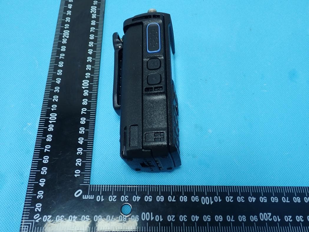
2BLTR-UVL15W
Jun 11, 2026Dual Band Two Way Radio
Equipment Class
DSS - Part 15 Spread Spectrum Transmitter
2BLTR-DUALBAND7800
Feb 12, 2026Dual Band Transceiver
Equipment Class
CSR - Scanning Receiver