2BRMO-TX15Outdoor Sensor
Fuzhou Smartwell Electronics Technology Co., Ltd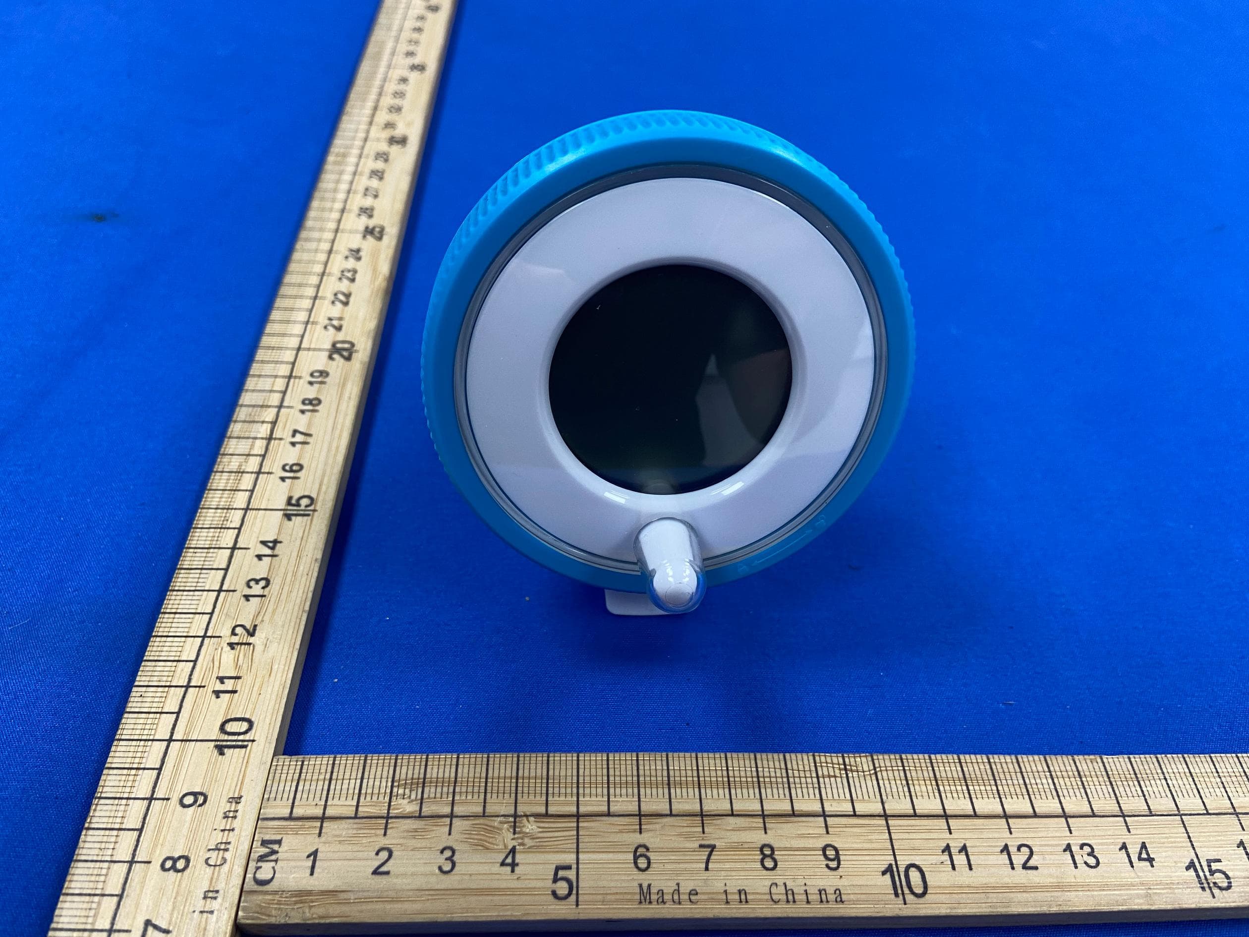
Click to zoom
Application Details
- Equipment Class
- DSC - Part 15 Security/Remote Control Transmitter
- Date of Grant
- Jul 15, 2026
- Application Purpose
- Original Equipment
- Equipment Note
- Outdoor Sensor
- Frequency Range
- 433.92200000 - 433.92200000
- Country
- China
Documents & Files
Document Text
Text extracted from the exhibit documents filed with the FCC. Open a document above to read the original.
Users Manual
Wireless Pool Thermometer Item No.233385 Lot number:2026.0401 User Manual Thank you for purchasing Geevon 233385 Wireless Pool Thermometer. Please read this manual and retain it for future reference. Features: · Time in optional 12/24 hour format · Swimming pool temperature detection · Comfort level display · Low battery indicate · Temperature display in optional °C/°F · Maximum / Minimum temperature and humidity record and query · Can take up to three outdoor transmitters · LED backlight · Indoor humidity range:20%RH~95%RH · Temperature measurement ranges: - Indoor: -9.9°C (14.2°F) ~ 50°C (122°F) - Outdoor: -40°C (-40°F) ~ 70°C (158°F) · Wireless parameter: - 3 Channels selectable - 433.92MHz RF transmitting frequency - 60 meter transmission range in an open area · Power Supply: - RX: 2 x LR03 size AAA - TX: 2 x LR03 size AAA Appearance description EN RX 1: Touch button (backlight) 2: Time 3: Comfort level display 4: Remote sensor channel 5: TX temperature 6: INDOOR temperature 7: INDOOR humidity 8: TX temperature MAX. Value 9: TX temperature MIN. Value 10: Battery compartment cover 11: Wall mounting hole EN TX A: Temperature sensor B: Battery box C: Main control module D: Waterproof rubber ring E: Lens F: Locking cover G: Positioning pin A H: Positioning pin B I: Transmitting antenna J: °C/°F selection switch K: Channel selection switch L: LED indicator for signal transmitting M: Channel N: Temperature value Initial operation · Open the Main Station battery compartment cover. · Insert 2 x AAA batteries observing polarity [ "+" and "-" marks ]. · When you insert the batteries, all icons on the LCD will light up for 3 seconds, and you will hear a beep tone, then detect indoor temperature & humidity. · The Main Station will now start to make a connection to the remote sensor, this operation takes about 3 minutes and will display by a flashing reception RF antenna symbol · This now, Open the remote sensor battery box. Insert 2 x AAA batteries observing polarity [ "+" and "-" marks ], Choose the temperature unit and channel you need. · The temperature unit °C/°F can be selected by turning the switch "J", the channel can be selected by turning the switch "K". EN + - + - Began to flash · After disassembly, do not touch other components, especially the antenna "I", pay attention to the direction of the slot when installing the battery box. After setting, align "H" with "G", cover the lens and waterproof ring, and lock the cover tightly. · This pairing mode only takes 3 minutes. If the pairing fails after more than 3 minutes, you need to press and hold the "CH" button for 2 seconds to re-enter 3 minutes pairing mode. · After successful pairing, the remote sensor can be put into the swimming pool to detect its water temperature. EN HG Wait three minutes Manual time setting · In normal mode, press and hold MODE button for 2 seconds, into the setting mode, the set item will blink display. Press "+" or "-" buttons to adjustment the value. Press MODE button to confirm the item has been set and go to the next one. The sequence of setting items is as follows: TIME format (12/24HR) -> HOUR -> MINUTE · Press MODE button to confirm the last item to end the setting procedures, then it will return to normal mode. F.Y.I.: · If there is no valid operation within 20 seconds, it will automatical- ly return to normal time mode from the set mode. EN Press the MODE button to enter setup mode. The clock area begins to flash. Press the + or - keys to adjust the value. Once you've finished setting it up, press the MODE button to proceed to the next item. 12 34 RF Transmission Procedure · The RX automatically starts receiving transmission from remote sensor for pool temperature after batteries inserted. · The remote sensor will automatically transmit temperature signal to the RX Station after batteries inserted. · If the RX failed to receive transmission from remote sensor ("- -.-" display on the LCD), press and hold "CH" button for 2 seconds to receive transmission manually, RF icon flashes on the LCD. EN If the LCD displays “-.-”, press and hold the CH button to rescan for the signal. · Press "CH" button to query CH2, CH3 data or cyclic display, When the symbol appears, it means that the data of three channels will be displayed circularly. 1 2 Query Maximum/minimum numerical value · When the indoor / outdoor temperature and humidity are shown in the LCD, the product began to record temperature and humidity maximum and minimum numerical value. · Press once MEM button, the LCD will display maximum value of temperature and humidity. The LCD will display the minimum value of temperature and humidity if you press once MEM button again when the maximum value is displayed. · At the same time, there are "MAX" or "MIN" displayed on the LCD. · The arrow in the lower right corner of the screen indicates the maximum and minimum outdoor temperature: The symbol indicates the maximum temperature The symbol indicates the minimum temperature · The temperature and humidity maximum/minimum value will RE records after press and hold MEM button 2 seconds, at the same time, there will be "- -.-" displayed in the LCD 2 second. · The memory value of the day will be automatically cleared at 0:00 every night. F.Y.I.: · If the temperature reading is below ranges, the LL.L will be displayed. If the temperature reading is above ranges, the HH.H will be displayed. EN MAX MIN Comfort level The temperature of the remote sensor is below 20°C(68°F); The temperature of the remote sensor is Between20°C (68°F) and 30°C (86°F); The temperature of the remote sensor is above 30°C(86°F). Low battery indicate When the symbol of low batteryappears in the INDOOR, it means that the RX needs to be replaced with new batteries. When the symbol of low batteryappears in the OUTDOOR, it means that the remote sensor needs to be replaced with new batteries. FCC Caution: This device complies with part 15 of the FCC Rules. Operation is subject to the following two cond…
Text truncated - open the document above for the full version.
Attestation Statements
FuzhouSmartwellElectronicsTechnologyCo.,Ltd CoveredEquipmentCertificationAttestationLetter 7/9/2026 NemkoNorthAmerica,Inc. 303RiverRoad Ottawa K1V1H2 Canada ATTN.:ReviewingEngineer FCCID:2BRMO-TX15 FuzhouSmartwellElectronicsTechnologyCo.,Ltd(“theapplicant”)certifiesthatthe equipmentforwhichauthorizationissoughtisnot“covered”equipmentprohibitedfrom receivinganequipmentauthorizationpursuanttosection2.903oftheFCCrules. Note:Iftheequipmentforwhichtheapplicantseeksauthorizationisproducedby anyoftheentitiesidentifiedonthecurrentCoveredList,theapplicantshould includeanexplanationonwhytheequipmentisnot“covered”equipment. FuzhouSmartwellElectronicsTechnologyCo.,Ltd(“theapplicant”)certifiesthat,asof thedateofthefilingoftheapplication,theapplicantisnotidentifiedontheCoveredList asanentityproducing“covered”equipment. FuzhouSmartwellElectronicsTechnologyCo.,Ltd(“theapplicant”)certifiesthatthe equipmentforwhichauthorizationissoughtdoesnotincludecybersecurityoranti-virus softwareproducedorprovidedbyKasperskyLab,Inc.oranyofitssuccessorsand assignees,includingequipmentwithintegratedKasperskyLab,Inc.(oranyofits successorsandassignees)cybersecurityoranti-virussoftwarepursuanttoDA-24-886 andKDB986446D01CoveredEquipmentGuidancesectionB(2a). Signed: Printedname:XianghuiLin Title:GeneralManager CompanyName:FuzhouSmartwellElectronicsTechnologyCo.,Ltd Date:7/9/2026
Cover Letter(s)
FuzhouSmartwellElectronicsTechnologyCo.,Ltd 7/9/2026 NemkoNorthAmerica,Inc. 303RiverRoad Ottawa,Ontario,Canada K1V1H2 REQUESTFORCONFIDENTIALITY-FCC FCCID:2BRMO-TX15 PursuanttoSections0.457(d)(1)(ii)and0.459oftheCommission’sRulesandFCCGuidance document726920,weherebyrequestconfidentialtreatmentofinformationaccompanyingthis applicationasoutlinedbelow: PERMANENTLONG-TERMCONFIDENTIALITY: Schematics BlockDiagrams TheoryofOperation Theaboveinformationcontainstradesecretsandproprietaryinformationnotcustomarilyreleasedto thepublic.Thepublicdisclosureofthisinformationmightbeharmfultotheapplicantandprovide unjustifiedbenefitstoitscompetitors.TheApplicantunderstandsthatpursuanttoRule0.457(d)(1)(ii), disclosureofthisApplicationandallaccompanyingmaterialswillnotbemadebeforethedateofthe GrantforthisApplication. Sincerely, Signed: Printedname:XianghuiLin Title:GeneralManager
External Photos
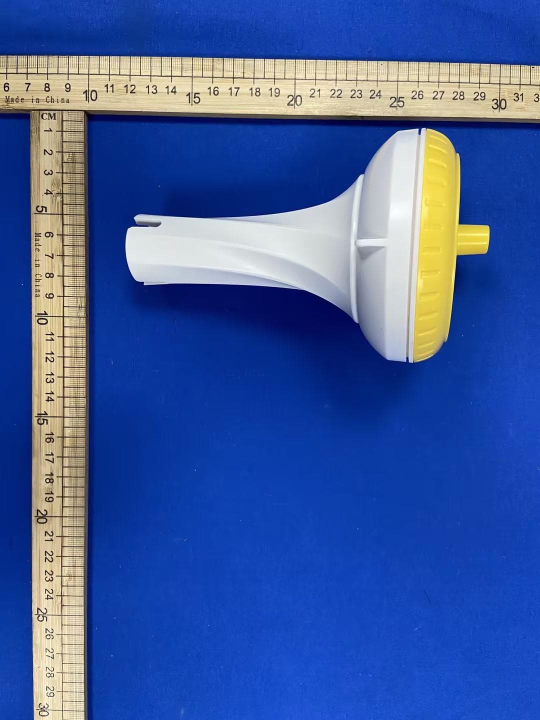
FCCID:2BRMO-TX15 FCCID:2BRMO-TX15 FCCID:2BRMO-TX15 FCCID:2BRMO-TX15
ID Label/Location Info
LabelandLabelLocation Model:TX15 FCCID:2BRMO-TX15
Internal Photos
FCCID:2BRMO-TX15 FCCID:2BRMO-TX15 FCCID:2BRMO-TX15
RF Exposure Info
Page 1 of 3 RF EXPOSURE EVALUATION FCC ID: 2BRMO-TX15 Product Name : Outdoor Sensor Model Name : TX15 Operating frequency : 433.922MHz Numbers of Channel : 1channels for SRD Antenna Type : Spring antenna Antenna Gain : 0dBi Type of Modulation : ASK Power supply : DC 3V Hardware Version : N/A Software Version : N/A Page 2 of 3 Standard Requirement According to § 15.231 and § 1.1307b(1), systems operating under the provisions of this section shall be operated in a manner that ensures that the public is not exposed to radio frequency energy levels in excess of the Commission’s guidelines. See KDB 447498 D01 General RF Exposure Guidance v06, section 4. 3. 1. The 1-g and 10-g SAR test exclusion thresholds for 100MHz to 6GHz at test separation distances ≤ 50mm are determined by: [ (max. power of channel, including tune-up tolerance, mW)/(min. test separation distance, mm)]*[ √f(GHz)] ≤3.0 for 1-g SAR and ≤7.5 for 10-g SAR extremity SAR, where ⚫ f(GHz) is the RF channel transmit frequency in GHz ⚫ Power and distance are rounded to the nearest mW and mm before calculation ⚫ The result is rounded to one decimal place for comparison. The test exclusions are applicable only when the minimum test separation distance is ≤ 50mm and for transmission frequencies between 100MHz and 6GHz. When the minimum test separation distance is <5mm, a distance of 5mm is applied to determine SAR test exclusion. Routine SAR evaluation refers to that specifically required by § 2.1093, using measurements or computer simulation. When routine SAR evaluation is not required, portable transmitters with output power greater than the applicable low threshold require SAR evaluation to quality for TCB approval. RF Output power Freq. (MHz) Field strength(max)(dBuV/m) EIRP (max) (dBm) 433.922 79.08 -16.12 Note: EIRP=E-104.8+20logD, Where E is the electric field strength in dBμV/m. EIRP is the equivalent isotropically radiated power in dBm. d is the specified measurement distance in m. where D=3, EIRP=E-95.2. Page 3 of 3 Channel (MHz) Maximum output power (dBm) Tune up tolerance (dBm) Max Tune Up Power (mW) Distance (mm) Calculation results Limit Operating Mode 433.922 -16.12 -16.12±1 0.030761 5 0.004053 3 SRD According to KDB 447498, The device only support SRD function, and no simultaneous SAR measurement is required. Signature Simon Pu Manager Date: 2026-06-29
Test Report
FCCTESTREPORT FCCID:2BRMO-TX15 Product: OutdoorSensor ModelName: TX15 Brand: N/A ReportNo.: PTC26032616201E-FC01 Preparedfor FuzhouSmartwellElectronicsTechnologyCo.,Ltd 1106,11thFloor,Building19,PhaseII,InnovationPark,No.7WulongjiangMiddle Avenue,MinhouCounty,Fuzhou,Fujian,China Preparedby PreciseTesting&CertificationCo.,Ltd Building1,No.6,TongxinRoad,DongchengStreet,Dongguan,Guangdong,China ReportNo.:PTC26032616201E-FC01 Page 2 of 32 1.TESTRESULTCERTIFICATION Applicant’sname: FuzhouSmartwellElectronicsTechnologyCo.,Ltd Address: 1106,11thFloor,Building19,PhaseII,InnovationPark,No.7 WulongjiangMiddleAvenue,MinhouCounty,Fuzhou,Fujian,China Manufacture'sname: FuzhouSmartwellElectronicsTechnologyCo.,Ltd Address: 1106,11thFloor,Building19,PhaseII,InnovationPark,No.7 WulongjiangMiddleAvenue,MinhouCounty,Fuzhou,Fujian,China Product: OutdoorSensor Model: TX15 Standards :FCCCFR47Part15Section15.231 Testprocedure :ANSIC63.10-2020 TestDate: May.16,2026toJun.29,2026 DateofIssue: Jun.29,2026 TestResult :Pass ThisdevicedescribedabovehasbeentestedbyPTC,andthetestresultsshowthatthe equipmentundertest(EUT)isincompliancewiththeFCCrequirements.Anditisapplicable onlytothetestedsampleidentifiedinthereport. Thisreportshallnotbereproducedexceptinfull,withoutthewrittenapprovalofPTC,this documentmaybealteredorrevisedbyPTC,personalonly,andshallbenotedintherevision ofthedocument. TestEngineer: Jackzhou/Engineer TechnicalManager: SimonPu/Manager ReportNo.:PTC26032616201E-FC01 Page 3 of 32 Contents 2TESTSUMMARY...............................................................................................................................................4 3GENERALINFORMATION..............................................................................................................................5 3.1GENERALDESCRIPTIONOFE.U.T..........................................................................................................5 3.2TESTMODE..............................................................................................................................................5 3.3TESTSITE.................................................................................................................................................5 3.4DESCRIPTIONOFSUPPORTUNITS..........................................................................................................6 4EQUIPMENTDURINGTEST...........................................................................................................................7 4.1EQUIPMENTSLIST....................................................................................................................................7 4.2MEASUREMENTUNCERTAINTY................................................................................................................7 5CONDUCTEDEMISSION.................................................................................................................................8 5.1E.U.T.OPERATION..................................................................................................................................8 5.2EUTSETUP..............................................................................................................................................8 5.3TESTSET-UP(BLOCKDIAGRAMOFCONFIGURATION)........................................................................9 5.4MEASUREMENTPROCEDURE..................................................................................................................9 5.5CONDUCTEDEMISSIONLIMIT..................................................................................................................9 5.6MEASUREMENTDESCRIPTION.................................................................................................................9 5.7CONDUCTEDEMISSIONTESTRESULT....................................................................................................9 6PULSEDOPERATION....................................................................................................................................10 6.1TESTSETUP...........................................................................................................................................10 7RADIATEDSPURIOUSEMISSIONS...........................................................................................................14 7.1EUTOPERATION....................................................................................................................................15 7.2TESTSETUP...........................................................................................................................................16 7.3SPECTRUMANALYZERSETUP...............................................................................................................17 7.4TESTPROCEDURE.................................................................................................................................18 7.5SUMMARYOFTESTRESULTS...............................................................................................................19 820DBBANDWIDTHMEASUREMENT.........................................................................................................23 8.1TESTPROCEDURE.................................................................................................................................23 8.2TESTSETUP...........................................................................................................................................23 8.3TESTRESULT.........................................................................................................................................24 9ANTENNAREQUIREMENT...........................................................................................................................25 10TESTSETUP..................................................................................................................................................2…
Text truncated - open the document above for the full version.
Test Report
Antennaspecification Manufacture'sname:WenzhouZhuoyueSpringCo.,Ltd. Address:No.1,Lane2,ShuangshiRoad,DajieVillage,ShifanStreet,Yueqing City,WenzhouCity,ZhejiangProvince Operatingfrequency:433.922MHz AntennaType:Integratedantenna AntennaGain:0dBi Antennasizediagram:
Test Setup Photos
FCCID:2BRMO-TX15 RadiatedSpuriousEmissions From30MHz-1000MHz TestfrequencyfromAbove1GHz
Contact Information
Applicant
Xianghui Lin
[email protected]Fax: N/A
Technical Contact
MIRAMONT SOLUTIONS LLCWenyi Wang
19 GEORGETOWN, IRVINE · IRVINE, 92612 · United States
Test Firm
Precise Testing & Certification Co., LTD.Yang Juan
Technical Specifications
| # | Rule Parts | Frequency Range | Power Output |
|---|---|---|---|
| 1 | 15.231 | 433.922 MHz - 433.922 MHz | - |
Other Applications from Fuzhou Smartwell Electronics Technology Co., Ltd
2BRMO-TX32
Jul 21, 2026Outdoor Sensor
Equipment Class
DSC - Part 15 Security/Remote Control Transmitter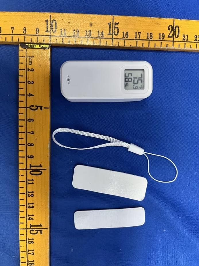
2BRMO-26TH13
Jul 06, 2026WiFi Temp & Humidity Sensor
Equipment Class
DTS - Digital Transmission System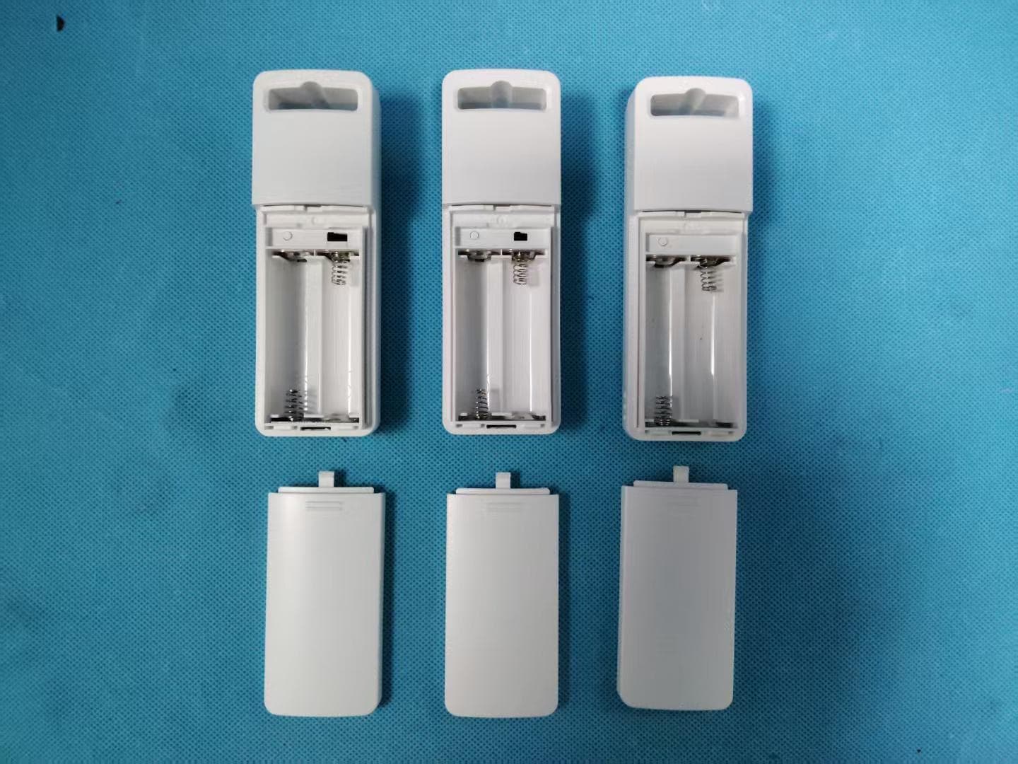
2BRMO-TX33
Mar 20, 2026Sensor
Equipment Class
DSC - Part 15 Security/Remote Control Transmitter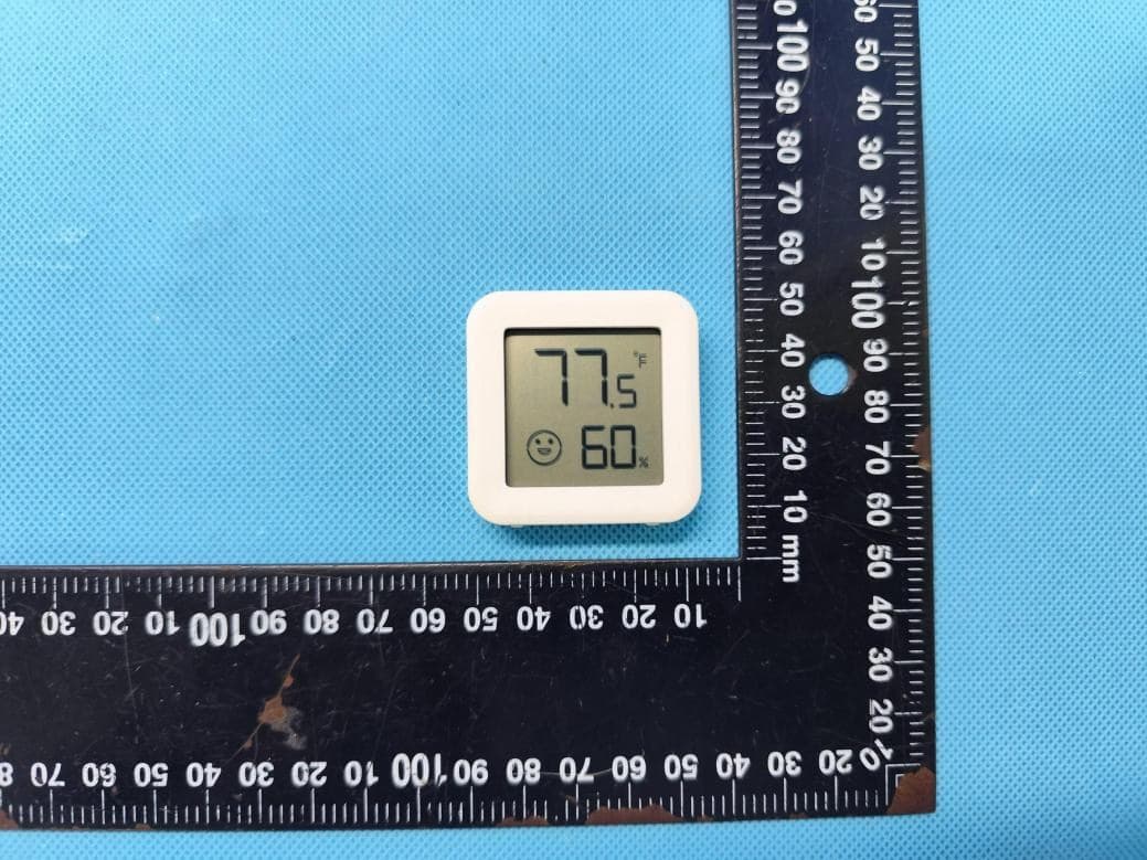
2BRMO-25TH05
Dec 01, 2025Wireless Thermometer and Hygrometer
Equipment Class
DTS - Digital Transmission System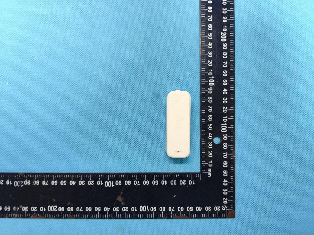
2BRMO-25TH11
Dec 01, 2025Temp & Humidity Sensor
Equipment Class
DTS - Digital Transmission System