2BSNU-EFSV01CID01This product receives birth alerts from the sensor placed on the animal and sends a text message or voice message to the farmer.
Innoval
Click to zoom
Application Details
- Equipment Class
- DTS - Digital Transmission System
- Date of Grant
- Dec 24, 2025
- Application Purpose
- Original Equipment
- Equipment Note
- This product receives birth alerts from the sensor placed on the animal and sends a text message or voice message to the farmer.
- Frequency Range
- 915.00000000 - 915.00000000
- Company
- Innoval
- Country
- France
Documents & Files
Document Text
Text extracted from the exhibit documents filed with the FCC. Open a document above to read the original.
Users Manual
USER GUIDE Foaling detection Congratulations, you have just purchased EasyFoal, the non- invasive and easy to use foaling detection system. Due to its sensor positioned on the tail, EasyFoal measures the mare’s ch a racte ristic behavioural sequences just before foaling. EasyFoal alerts you by SMS and voice call when the first signs of foaling appear. The steps described in this guide will allow you to install your EasyFoal system independently. If necessary, you can contact your supplier’s customer service department at any time. Contents P3 Preamble Precautions to be taken Safety and responsability Disposal P4 Presentation of the equipment The collector The power chord The sensor The adhesive tape P5 Easyfoal Search tool – user guide P6 Supply and insert a SIM card P7 First installation guide P8 Positioning the collector Switching on the collector Network coverage P9 Connecting additional sensors Starting the sensors Checking the coverage area P10 Recipient setting System communication test P11 Fixing the sensor P12 Storing and testing the sensors Storing the sensors Reusing a sensor Changing recipients Adding a new sensor Sensor test P13 Uninstalling and reinstalling the collector between foaling seasons Shutting down the system at the end of the season Reinstalling the system at the start of the season Recharging the outdoor collector P14 Restarting your system after a down period P15 Please note Reminder of performances Recommendations in case of undetected foaling p16 After-Sales service P17 Summary of SMS commands P18 Appendices Preamble This user manual concerns the Radio Base and the monitoring tools of the INNOVAL company. Please read this manual carefully before using the equipment for the first time. The recipes (documents provided with your monitoring equipment) remind you in a condensed manner the good practices and main points of care that we request you to follow everyday. Keep the user manuals, recipe and all other directives that come with your monitoring tool so that you can refer to them when required. Observe and respect all instructions described in this manual or affixed on the equipment and in particular the following precautions. With a view to continuous improvement of our products, we reserve the right to modify their characteristics for technical advancement. Precautions to be taken The equipment described in this manual is for professional use only. Sensors equipment Never expose the sensors to a temperature greater than 60° C ( 140°F) Only use accessories specifically recommended by INNOVAL with the INNOVAL kits. For any technical question, contact INNOVAL by email : [email protected] or by telephone +33 (0)2 xx xx xx xx Troubleshooting For troubleshooting, contact INNOVAL by providing as reference the item number and serial number present on your kit components. Any repair of kit components must be carried out by a service centre authorized by INNOVAL at the risk of cancellation of the guarantee. Safety and responsibility The equipment must be installed by a professional. Under no circumstances may INNOVAL be held liable to the customer, his employees, successors and beneficiaries, for any special, consequential damage or financial loss of whatsoever description, including but not limited to losses, costs, revenue or interests, suffered by the customer or any third-party on account of a defect or loss of use of all or part of the kit. It is expressly mentioned that INNOVAL may not be held liable for the non-receipt of an SMS message sent by the Radio Base to a fixed or mobile phone. The transmission of SMS messages is the responsibility of telecommunication operators, the quality of whose services cannot be guaranteed by INNOVAL. The total and cumulative responsibility of INNOVAL as part of or in connection with the use of the current Radio Base and the sensors for any purpose whatsoever will on no account exceed one hundred percent (100%) of the amount paid by the customer for the purchase of his monitoring tool. Any changes or modifications not expressly approved by INNOVAL could void the user's authority to operate the equipment. Disposal During disposal of the equipment, its owner will have to ensure that the different components are discarded in accordance with the current legislation in the country where the equipment is destroyed. These recommendations must be taken into account particularly for the following components: • The Radio Base battery • Metal components (welded or otherwise, untreated or painted, etc.) • Plastic components (applicator, appendages, etc.) • Electronic components (boards, display, antennae, etc.) • Electrical components (charger, etc.) Presentation of the equipment Your EasyFoal kit includes the following items THE COLLECTOR The collector is the element that relays the information from the sensor to the breeder’s phone. It communicates with the sensors by LoRa radio wave. The range of the radio antenna is about 1000m around the collector. This area can be reduced if there are major obstacles (storage building, metal cladding, wood...). The collector can communicate with an unlimited number of collectors. Its parameter setting is done using SMS commands which are detailed in this guide. Your collector requires a SIM card to operate. Please refer to page 5 of this guide for further details. There are two versions of the collector. THE SENSOR The sensor uses an accelerometer to accurately measure the mare’s movements. It has a direction of use indicated by an arrow. The electronic board is embedded in a special resin which protects it from oxidation and damage. The sensor requires no maintenance. It is waterproof (IP 65], but we recommend not immersing it in water. The sensor is powered by a non-rechargeable lithium battery. At the end of its life, it will send you a low battery warning. It is therefore recommended that you return it to the manufacturer. The sensor can be identified by a serial number that you will use to set u…
Text truncated - open the document above for the full version.
Users Manual
Congratulations, you have just purchased Smartvel, the non- invasive and easy to use calving detection system. Due to its sensor positioned on the tail, Smartvel measures the mare’s characteristic behavioural sequences just before calving. Smartvel alerts you by SMS and voice call when the first signs of calving appear. The steps described in this guide will allow you to install your Smartvel system independently. If necessary, you can contact your supplier’s customer service department at any time. Contents P3 Preamble Precautions to be taken Safety and responsability Disposal P4 Presentation of the equipment The collector The power chord The sensor The adhesive tape P5 Smartvel Search tool – user guide P6 Supply and insert a SIM card P7 First installation guide P8 Positioning the collector Switching on the collector Network coverage P9 Connecting additional sensors Starting the sensors Checking the coverage area P10 Recipient setting System communication test P11 Fixing the sensor P12 Storing and testing the sensors Storing the sensors Reusing a sensor Changing recipients Adding a new sensor Sensor test P13 Uninstalling and reinstalling the collector between calving seasons Shutting down the system at the end of the season Reinstalling the system at the start of the season Recharging the outdoor collector P14 Restarting your system after a down period P15 Please note Reminder of performances Recommendations in case of undetected calving p16 After-Sales service P17 Summary of SMS commands P18 Appendices Preamble This user manual concerns the Radio Base and the monitoring tools of the INNOVAL company. Please read this manual carefully before using the equipment for the first time. The recipes (documents provided with your monitoring equipment) remind you in a condensed manner the good practices and main points of care that we request you to follow everyday. Keep the user manuals, recipe and all other directives that come with your monitoring tool so that you can refer to them when required. Observe and respect all instructions described in this manual or affixed on the equipment and in particular the following precautions. With a view to continuous improvement of our products, we reserve the right to modify their characteristics for technical advancement. Precautions to be taken The equipment described in this manual is for professional use only. Sensors equipment Never expose the sensors to a temperature greater than 60° C ( 140°F) Only use accessories specifically recommended by INNOVAL with the INNOVAL kits. For any technical question, contact INNOVAL by email : [email protected] or by telephone +33 (0)2 xx xx xx xx Troubleshooting For troubleshooting, contact INNOVAL by providing as reference the item number and serial number present on your kit components. Any repair of kit components must be carried out by a service centre authorized by INNOVAL at the risk of cancellation of the guarantee. Safety and responsibility The equipment must be installed by a professional. Under no circumstances may INNOVAL be held liable to the customer, his employees, successors and beneficiaries, for any special, consequential damage or financial loss of whatsoever description, including but not limited to losses, costs, revenue or interests, suffered by the customer or any third-party on account of a defect or loss of use of all or part of the kit. It is expressly mentioned that INNOVAL may not be held liable for the non-receipt of an SMS message sent by the Radio Base to a fixed or mobile phone. The transmission of SMS messages is the responsibility of telecommunication operators, the quality of whose services cannot be guaranteed by INNOVAL. The total and cumulative responsibility of INNOVAL as part of or in connection with the use of the current Radio Base and the sensors for any purpose whatsoever will on no account exceed one hundred percent (100%) of the amount paid by the customer for the purchase of his monitoring tool. Any changes or modifications not expressly approved by INNOVAL could void the user's authority to operate the equipment. Disposal During disposal of the equipment, its owner will have to ensure that the different components are discarded in accordance with the current legislation in the country where the equipment is destroyed. These recommendations must be taken into account particularly for the following components: • The Radio Base battery • Metal components (welded or otherwise, untreated or painted, etc.) • Plastic components (applicator, appendages, etc.) • Electronic components (boards, display, antennae, etc.) • Electrical components (charger, etc.) Presentation of the equipment Your Smartvel kit includes the following items THE COLLECTOR The collector is the element that relays the information from the sensor to the breeder’s phone. It communicates with the sensors by LoRa radio wave. The range of the radio antenna is about 1000m around the collector. This area can be reduced if there are major obstacles (storage building, metal cladding, wood...). The collector can communicate with an unlimited number of collectors. Its parameter setting is done using SMS commands which are detailed in this guide. Your collector requires a SIM card to operate. Please refer to page 5 of this guide for further details. There are two versions of the collector. THE SENSOR The sensor uses an accelerometer to accurately measure the mare’s movements. It has a direction of use indicated by an arrow. The electronic board is embedded in a special resin which protects it from oxidation and damage. The sensor requires no maintenance. It is waterproof (IP 65], but we recommend not immersing it in water. The sensor is powered by a non-rechargeable lithium battery. At the end of its life, it will send you a low battery warning. It is therefore recommended that you return it to the manufacturer. The sensor can be identified by a serial number that you will use to set up the system. INDOOR non-waterpr…
Text truncated - open the document above for the full version.
Internal Photos
IntPho LoRa antenna coaxial cable soldered here 2 x 4G antenna coaxial cable soldered here
Test Report
GigaConcept - 20 rue Louise de Vilmorin - ZA des Marsandes - 91630 Avrainville - FRANCE Tél : +33 (0)1 60 82 86 33 - Fax : +33 (0)1 60 82 06 82 - www.giga-concept.fr | Page 1 Antenne combinée 2×[4G-LTE 3G/2G LPWA]Antenne combinée 2×[4G-LTE 3G/2G LPWA] IP67/IP69/IK09 traversante | 0.6 à 4.1dBiIP67/IP69/IK09 traversante | 0.6 à 4.1dBi RéférenceRéférence GC-7724Ba GainGain0.6dBi à 4.1dBi ConnecteurConnecteurSMA (M) Dimensions (mm)Dimensions (mm)Ø 60 × 69 mm T° de fonctionnementT° de fonctionnement-40°C à +85°C CARACTÉRISTIQUESCARACTÉRISTIQUES Câble 1 : 2G/3G/4G - IoT/LPWANCâble 1 : 2G/3G/4G - IoT/LPWAN BANDE(S) (MHZ)BANDE(S) (MHZ) 700/850/9001700/1800/1900/21002600 FRÉQUENCE(S) (MHZ)FRÉQUENCE(S) (MHZ) 698-9601710-21702500-2700 PERTE DE RETOUR (DB)PERTE DE RETOUR (DB) ~-6.9~-15.3~-16,7 VSWRVSWR ~2.9:1~1.4:1~1.4:1 EFFICACITÉ (%)EFFICACITÉ (%) ~37,8~53,3~54,9 GAIN MAXIMAL (DBI)GAIN MAXIMAL (DBI) ~-0,8~3,6~4.1 GAIN MOYEN (DB)GAIN MOYEN (DB) ~-4.3~-2,7~-2.6 IMPÉDANCE (OHMS)IMPÉDANCE (OHMS) 50 POLARISATIONPOLARISATION Linéaire RAYONNEMENTRAYONNEMENT Omnidirectionnel PUISSANCE D'ENTRÉE MAX.(W)PUISSANCE D'ENTRÉE MAX.(W) 25 CONNECTEURCONNECTEUR Norme SMA-Mâle (autres connecteurs disponibles) LONGUEUR DE CÂBLELONGUEUR DE CÂBLE 300 cm standard (toute longueur de câble disponible) TYPE DE CÂBLETYPE DE CÂBLE Norme LL100 (autres câbles disponibles) Conditions de mesure de l'antenne : Conditions de mesure de l'antenne : - Montée sur un plan de masse de 30 × 30 cm - 200 cm de Câble LL100 - Mesurée dans une chambre anéchoïque CTIA 3D certifiée GigaConcept - 20 rue Louise de Vilmorin - ZA des Marsandes - 91630 Avrainville - FRANCE Tél : +33 (0)1 60 82 86 33 - Fax : +33 (0)1 60 82 06 82 - www.giga-concept.fr | Page 2 Câble 2 : 2G/3G/4G - IoT/LPWANCâble 2 : 2G/3G/4G - IoT/LPWAN BANDE(S) (MHZ)BANDE(S) (MHZ) 700/850/9001700/1800/1900/21002600 FRÉQUENCE(S) (MHZ)FRÉQUENCE(S) (MHZ) 698-9601710-21702500-2700 PERTE DE RETOUR (DB)PERTE DE RETOUR (DB) ~-6.8~-14.3~-9.3 VSWRVSWR ~2.8:1~1.5:1~2.1:1 EFFICACITÉ (%)EFFICACITÉ (%) ~38,7~52,3~42,1 GAIN MAXIMAL (DBI)GAIN MAXIMAL (DBI) ~-0,6~2,9~3.0 GAIN MOYEN (DB)GAIN MOYEN (DB) ~-4.2~-2.8~-3.8 IMPÉDANCE (OHMS)IMPÉDANCE (OHMS) 50 POLARISATIONPOLARISATION Linéaire RAYONNEMENTRAYONNEMENT Omnidirectionnel PUISSANCE D'ENTRÉE MAX.(W)PUISSANCE D'ENTRÉE MAX.(W) 25 CONNECTEURCONNECTEUR Norme SMA-Mâle (autres connecteurs disponibles) LONGUEUR DE CÂBLELONGUEUR DE CÂBLE 300 cm standard (toute longueur de câble disponible) TYPE DE CÂBLETYPE DE CÂBLE Norme LL100 (autres câbles disponibles) Caractéristiques communes câbles 1 et 2 :Caractéristiques communes câbles 1 et 2 : CONNECTEURCONNECTEUR Norme SMA-Mâle (autres connecteurs disponibles) LONGUEUR DE CÂBLELONGUEUR DE CÂBLE 300 cm standard (toute longueur de câble disponible) TYPE DE CÂBLETYPE DE CÂBLE Norme LL100 (autres câbles disponibles) GigaConcept - 20 rue Louise de Vilmorin - ZA des Marsandes - 91630 Avrainville - FRANCE Tél : +33 (0)1 60 82 86 33 - Fax : +33 (0)1 60 82 06 82 - www.giga-concept.fr | Page 3 SPÉCIFICATIONSSPÉCIFICATIONS TYPE DE MONTAGETYPE DE MONTAGE Traversant / Montage vis DIMENSIONS (MM)DIMENSIONS (MM) Ø 60 × 69 COUPLE DE SERRAGE MAX.(NM)COUPLE DE SERRAGE MAX.(NM) 6 MATÉRIAU RADÔMEMATÉRIAU RADÔME PC/ABS stable aux UV COULEUR RADÔMECOULEUR RADÔME Noir BASE D'ANTENNEBASE D'ANTENNE Zamac JOINT D'ÉTANCHÉITÉJOINT D'ÉTANCHÉITÉ TPE T° DE FONCTIONNEMENT (°C)T° DE FONCTIONNEMENT (°C) -40 à +85 T° DE STOCKAGE (°C)T° DE STOCKAGE (°C) -40 à +85 CERTIFICATION(S)CERTIFICATION(S) RoHS INDICE(S) DE PROTECTIONINDICE(S) DE PROTECTION IP67, IP69, IK09 ENVIRONNEMENTENVIRONNEMENT Cette gamme d’antenne est fabriquée sans matières dangereuses tout en maintenant une conformité totale avec REACH et RoHSREACH et RoHS. GigaConcept - 20 rue Louise de Vilmorin - ZA des Marsandes - 91630 Avrainville - FRANCE Tél : +33 (0)1 60 82 86 33 - Fax : +33 (0)1 60 82 06 82 - www.giga-concept.fr | Page 4 MESURESMESURES Câble 1 : 2G/3G/4G - IoT/LPWANCâble 1 : 2G/3G/4G - IoT/LPWAN GigaConcept - 20 rue Louise de Vilmorin - ZA des Marsandes - 91630 Avrainville - FRANCE Tél : +33 (0)1 60 82 86 33 - Fax : +33 (0)1 60 82 06 82 - www.giga-concept.fr | Page 5 GigaConcept - 20 rue Louise de Vilmorin - ZA des Marsandes - 91630 Avrainville - FRANCE Tél : +33 (0)1 60 82 86 33 - Fax : +33 (0)1 60 82 06 82 - www.giga-concept.fr | Page 6 Câble 2 : 2G/3G/4G - IoT/LPWANCâble 2 : 2G/3G/4G - IoT/LPWAN GigaConcept - 20 rue Louise de Vilmorin - ZA des Marsandes - 91630 Avrainville - FRANCE Tél : +33 (0)1 60 82 86 33 - Fax : +33 (0)1 60 82 06 82 - www.giga-concept.fr | Page 7 GigaConcept - 20 rue Louise de Vilmorin - ZA des Marsandes - 91630 Avrainville - FRANCE Tél : +33 (0)1 60 82 86 33 - Fax : +33 (0)1 60 82 06 82 - www.giga-concept.fr | Page 8 GigaConcept - 20 rue Louise de Vilmorin - ZA des Marsandes - 91630 Avrainville - FRANCE Tél : +33 (0)1 60 82 86 33 - Fax : +33 (0)1 60 82 06 82 - www.giga-concept.fr | Page 9 Isolation câble 1 et 2Isolation câble 1 et 2 Coefficient de corrélation de l'enveloppe câble 1 et 2Coefficient de corrélation de l'enveloppe câble 1 et 2 GigaConcept - 20 rue Louise de Vilmorin - ZA des Marsandes - 91630 Avrainville - FRANCE Tél : +33 (0)1 60 82 86 33 - Fax : +33 (0)1 60 82 06 82 - www.giga-concept.fr | Page 10 GigaConcept - 20 rue Louise de Vilmorin - ZA des Marsandes - 91630 Avrainville - FRANCE Tél : +33 (0)1 60 82 86 33 - Fax : +33 (0)1 60 82 06 82 - www.giga-concept.fr | Page 11 Câble 1 : 2G/3G/4G - IoT/LPWANCâble 1 : 2G/3G/4G - IoT/LPWAN GigaConcept - 20 rue Louise de Vilmorin - ZA des Marsandes - 91630 Avrainville - FRANCE Tél : +33 (0)1 60 82 86 33 - Fax : +33 (0)1 60 82 06 82 - www.giga-concept.fr | Page 12 GigaConcept - 20 rue Louise de Vilmorin - ZA des Marsandes - 91630 Avrainville - FRANCE Tél : +33 (0)1 60 82 86 33 - Fax : +33 (0)1 60 82 06 82 - www.giga-concept.fr | Page 13 Câble 2 : 2G/3G/4G - IoT/LPWANCâble 2 : 2G/3G/4G - IoT/LPWAN GigaConcept - 20 rue Louise de Vilmorin - ZA des Marsandes - 91630 Avrainville - FRANCE Tél : +33 (0)…
Text truncated - open the document above for the full version.
Test Report
GigaConcept - 20 rue Louise de Vilmorin - ZA des Marsandes - 91630 Avrainville - FRANCE Tél : +33 (0)1 60 82 86 33 - Fax : +33 (0)1 60 82 06 82 - www.giga-concept.fr | Page 1 Antenne 868 MHz / 915 MHz, traversante,Antenne 868 MHz / 915 MHz, traversante, omnidirectionnelle | 3.0dBiomnidirectionnelle | 3.0dBi RéférenceRéférence GC-409 GainGain3.0 dBi ConnecteurConnecteurSMA mâle ou autres Dimensions (mm)Dimensions (mm)Ø 10.9 × 227.5 T° de fonctionnementT° de fonctionnement-40°C à +65°C CARACTÉRISTIQUESCARACTÉRISTIQUES FRÉQUENCE(S) (MHZ)FRÉQUENCE(S) (MHZ) 868 ou 915 POLARISATIONPOLARISATION Linéaire GAIN DE CRÊTEGAIN DE CRÊTE 3.0dBi VSWRVSWR <2,0 IMPÉDANCE (OHMS)IMPÉDANCE (OHMS) 50Ω SPÉCIFICATIONSSPÉCIFICATIONS CÂBLECÂBLE RG178 ou autres CONNECTEURCONNECTEUR SMA male ou autres sur demande TYPE DE MONTAGETYPE DE MONTAGE Articulation ENVIRONNEMENTENVIRONNEMENT T° DE FONCTIONNEMENT (°C)T° DE FONCTIONNEMENT (°C) 40°C~+85°C VIBRATIONVIBRATION 10 à 55 Hz avec une amplitude de 1,5 mm 2 heures CERTIFICATION(S)CERTIFICATION(S) ROHS GigaConcept - 20 rue Louise de Vilmorin - ZA des Marsandes - 91630 Avrainville - FRANCE Tél : +33 (0)1 60 82 86 33 - Fax : +33 (0)1 60 82 06 82 - www.giga-concept.fr | Page 2 MESURESMESURES GigaConcept - 20 rue Louise de Vilmorin - ZA des Marsandes - 91630 Avrainville - FRANCE Tél : +33 (0)1 60 82 86 33 - Fax : +33 (0)1 60 82 06 82 - www.giga-concept.fr | Page 3 SCHÉMA(S)SCHÉMA(S)
Test Report
Siège Social : Emitech - 3, avenue des Coudriers - Z.A. de l’Observatoire - 78180 MONTIGNY LE BX - France Siret : 344 545 645 00022 - Tél. : 33 (0)1 30 57 55 55 - Fax : 33 (0)1 30 43 74 48 - E-mail : [email protected] - URL : www.emitech.fr SAS au capital de 1 560 000 € - R.C.S. VERSAILLES 344 545 645 - APE 7112B RRA-EMIESS24H695RFT-1A v0 Certain services reported in this document are not covered by the accreditation. They are identified by the symbol (*) Duplication of this test report is only permitted for an integral photographic facsimile. It includes the number of pages referenced here above. This document is the result of testing a specimen or a sample of the product submitted. It does not imply an assessment of the conformity of the whole manufactured products of the tested sample. LIST OF ACCREDITED SITES AND SCOPE AVALAIBLE ON WWW.COFRAC.FR TESTING ACCREDITATIONS N° 1-7460 Test report issued under the responsibility of: EMITECH ILE DE FRANCE Laboratory MRA US-EU Designation Number: FR0004 RADIO TESTS REPORT FCC 47 CFR PART 15 : 2025 Company ......................................... : INNOVAL Address. ............................................ : Rue Eric Tabarly 35530 NOYAL SUR VILAINE FRANCE Test item description. .................... : Farrowing detector Trade Mark. ...................................... : EASYFOAL Manufacturer..................................... : INNOVAL Model/Type reference. ...................... : Indoor collector Ratings. ............................................. : 100-240Vac/50-60Hz Testing Laboratory ......................... : EMITECH ILE DE France Laboratory Address. ............................................ : 30-32, avenue des 3 Peuples 78180 MONTIGNY-LE-BRETONNEUX - FRANCE Report Reference No. ..................... : RRA-EMIESS24H695RFT-1A v0 Test procedure. ................................ : FCC Certification Diffusion. ........................................... : M. PELTIER Applicant’s name. ............................. : RF TRACK Date of issue. .................................... : 13/10/2025 Total number of pages. ..................... : 44 Revision. ........................................... : 0 Compiled by. ..................................... : N. PEREZ (Test Technician) Technical verification & Quality approval. ........................................... : RRA-EMIESS24H695RFT-1A v0 Page 2 out of 44 REPORT INDEX: 1. GENERAL INFORMATION ............................................................................................................................. 3 2. REFERENCE DOCUMENTS .......................................................................................................................... 4 3. EQUIPMENT TECHNICAL DESCRIPTION .................................................................................................... 5 3.1. TEST CONDITIONS ................................................................................................................................... 5 3.2. E.U.T OVERVIEW .................................................................................................................................... 5 3.3. E.U.T MARKING PLATE ............................................................................................................................ 8 3.4. E.U.T MODIFICATIONS ............................................................................................................................. 8 3.5. E.U.T ELECTRONIC BOARD ...................................................................................................................... 8 3.6. E.U.T MECHANICAL AND ELECTRICAL DESIGN ........................................................................................... 9 3.7. E.U.T INPUT/OUTPUT PORTS.................................................................................................................... 9 3.8. SUPPORTING EQUIPMENT USED DURING TEST .......................................................................................... 9 4. RESULT SUMMARY .....................................................................................................................................11 5. EMC MEASUREMENT UNCERTAINTY .......................................................................................................13 6. TEST CONDITIONS AND RESULTS ...........................................................................................................14 6.1. MEASUREMENT OF CONDUCTED EMISSION ON AC MAINS PORTS ...............................................................14 6.2. DIGITAL MODULATION SYSTEMS ..............................................................................................................18 6.3. TRANSMITTER OUTPUT POWER ...............................................................................................................21 6.4. PEAK POWER SPECTRAL DENSITY ...........................................................................................................24 6.5. ADDITIONAL PROVISIONS TO THE GENERAL RADIATED EMISSIONS LIMITATION.............................................27 6.6. MEASUREMENT OF RADIATED DISTURBANCES ..........................................................................................31 REVISION HISTORY: Revision Date Modified pages Modifications 0 13/10/2025 / Creation RRA-EMIESS24H695RFT-1A v0 Page 3 out of 44 1. GENERAL INFORMATION TESTING PROCEDURE AND TESTING LOCATION: Testing Location ......................................... : EMITECH ILE DE France Laboratory Address. ....................................................... : 30-32, avenue des 3 Peuples 78180 MONTIGNY-LE-BRETONNEUX - FRANCE Test procedure. ............................................ : FCC Certification Tested by ...................................................... : N. PEREZ Test supervisor ............................................. : B. PELLERIN Date of receipt of test item ........................... : 0…
Text truncated - open the document above for the full version.
RF Exposure Info
Extphotos Top View Note : Non-removable antennas, with coaxial cables soldered internally directly onto the electronic boards
RF Exposure Info
RF EXPOSURE EVALUATION Equipment under test: Farrowing detector FCC ID: 2BSNU-EFSV01CID01 Test report reference: RRA-EMIESS24H695RFT-1A v0 MPE calculation These equations are generally accurate in the far field of an antenna but will over predict power density in the near field, where they could be used for making a “worst case” prediction. S = PG/4R² Where: S = power density (in appropriate units, e.g. mW/cm²) P = power input to the antenna (in appropriate units e.g. mW) G = power gain of the antenna in the direction of interest relative to the isotropic radiator R = distance to the centre of radiation of the antenna (appropriate units e.g. cm) Or S = EIRP/4R² Where EIRP = equivalent isotropically radiated power Calculation: (Calculated for max. EIRP) EIRP: 10.3 dBm (10.7 mW) for f=915.0 MHz Calculated at distance of 20 cm: Power density = 0.002 mW/cm² Limit: 3.05 mW/cm² is the reference level for G Exposure according to Rule part 1.1310(e) Ed. Date Modified page(s) Technical Verification and Quality Approval Name / Visa 0 25/11/2025 Creation Siège Social : Emitech - 3, rue des Coudriers - Z.A. de l’Observatoire - 78180 MONTIGNY LE BX - France Siret : 344 545 645 00022 - Tél. : 33 (0)1 30 57 55 55 - Fax : 33 (0)1 30 43 74 48 - E-mail : [email protected] - URL : www.emitech.fr S.A. au capital de 1 560 000 € - R.C.S. VERSAILLES 344 545 645 - APE 7112B
Operational Description
Collector Indoor. FCC ID : 2BSNU-EFSV01CID01 THE COLLECTOR INDOOR Functionnal description : When a birth is detected (foal or calf), the sensor positioned on the animal sends an alert to the outdoor collector via the LoRa modem. The collector receives birth alerts from the sensor placed on the animal and sends a text message or voice message to the farmer’s phone, via 4G cellular network. This collector outdoor is used for two applications: • foaling detection with the system name EASYFOAL • and calving detection with the system name SMARTVEL Internal functions : The collecteur Indoor (EASYFOAL system (for mares) or SMARTVEL system (for cows)) is powered by an external AC/DC converter (8.1V/2.5A, two-point plug without grounding) and contains • a cellular 4G modem with a 4G antenna • a LoRa modem with a LoRa antenna • a microcontroller that manages all electronic functions Note : The Wifi transceiver is not used in the application. It is not wired on the collector. LoRa modulation description : • Modulation : LoRa • Frequency : 915MHz • Spreading factor : SF10 • Bandwidth : 500KHz • Error coding : 4/5 The LoRa Antenna is a GC-409-150, from Gigaconcept. It can’t be removed. LoRa Protocol description : The transmissions are foaling, calving, or battery alert alarms, which are rare events. The gateway listens every 250 ms (RX in green) at a frequency of 915 MHz. If it detects a wake-up signal from the sensor at a frequency of 915 MHz, it waits for the message (red) and then immediately responds with an acknowledgment (in blue), which completes the procedure. If the acknowledgment is not received by the sensor, it immediately resends the message and waits for acknowledgment. If, after 3 acknowledgment requests, the sensor has not received anything, it repeats the procedure after 6 minutes, then 12 minutes, then 24 minutes if it still does not receive an acknowledgment. If it still has not received the acknowledgment at the end of these 24 minutes, it stops the procedure. The total alert transmission duration is 350ms including the 250ms duration of the wake up and the message. The acknowledgement duration is 80ms. The communications uses CAD (Chanel Activity Detection) before transmission, wich means that it listens if the chanel is occupied before any transmission. The range of the LoRa link is about 500m around the collector. This area can be reduced if there are major obstacles (storage building, metal cladding, wood...). The collector can communicate with an unlimited number of sensors. Cellular messages : The collector microcontroller then analyzes this alert and sends an SMS or Voice message to the farmer via the cellular 4G FCC certified modem . The collector contains the modem SIM7600G (FCC ID 2AJYU-8PYA008) to communicate on the cellular network. It requires a SIM card to operate. The cellular antenna is a GC-7724Ba, from Gigaconcept. It can’t be removed. Mechanical description : The aluminium enclosure is a 1455N1201 from Hammond c…
Text truncated - open the document above for the full version.
Contact Information
Applicant
Emmanuel FOURNIER(CEO of INNOVAL Cooperative)
[email protected]Fax: 0000000000
Technical Contact
FarmVet.com, INCEmilie Bond
1254 Old Hillsboro Rd · Francklin, Tennessee, 37069 · United States
Test Firm
EMITECH MontignyBruno Pellerin
[email protected]Fax: 33-1-30-48-00-35
Technical Specifications
| # | Rule Parts | Frequency Range | Power Output |
|---|---|---|---|
| 1 | 15C | 915 MHz - 915 MHz | 10.70 mW |
Other Applications from Innoval

2BSNU-EFSV01STO01
Jan 02, 2026The search tool uses LoRa modem to ask the sensor for the level of RF signal it is receiving. The closer it gets, the higher the level increases
Equipment Class
DTS - Digital Transmission System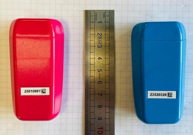
2BSNU-EFSV01SENO1
Dec 24, 2025The sensor analyzes the animals movements, detects birth, and sends an alert to the collector via the LoRa modem.
Equipment Class
DTS - Digital Transmission System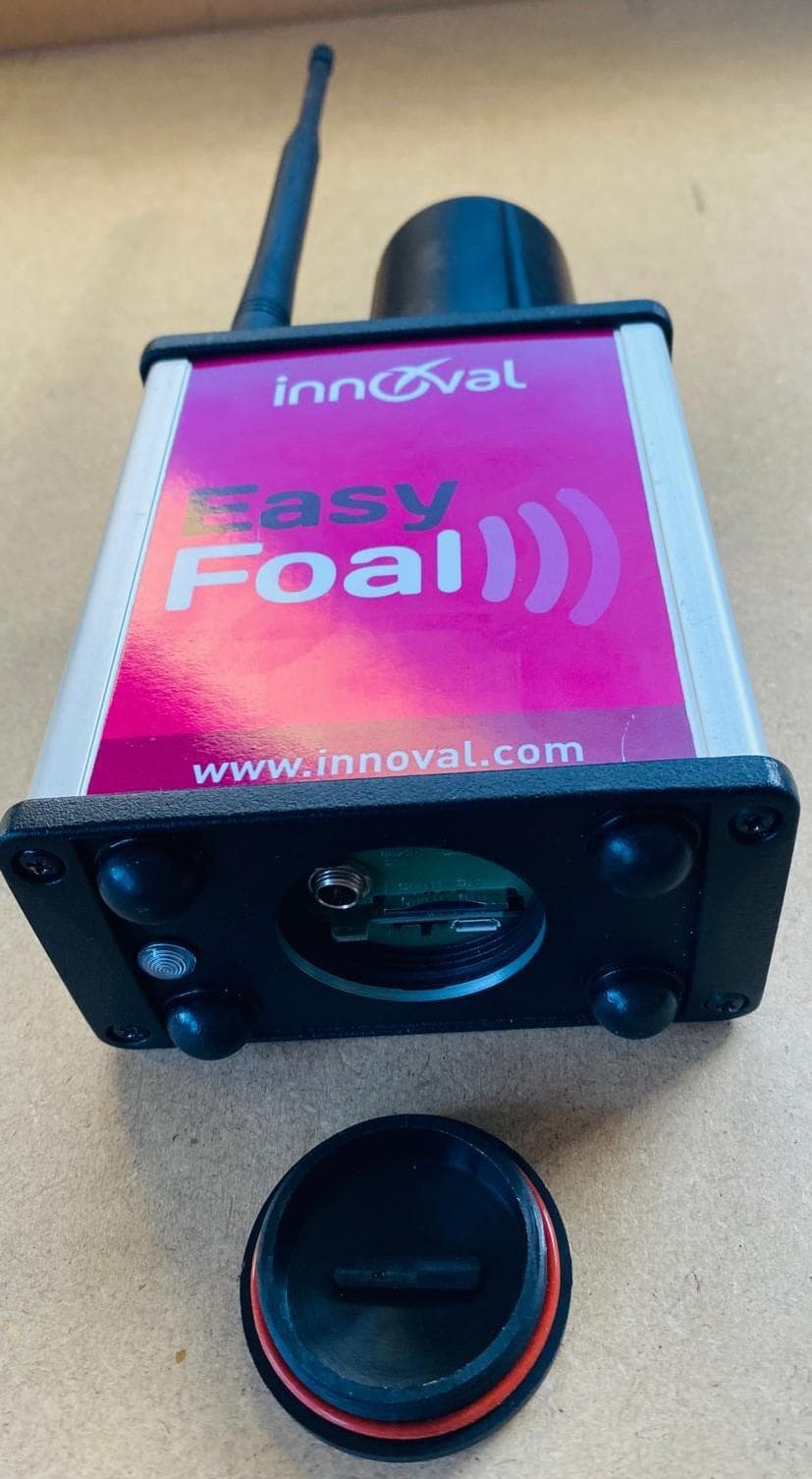
2BSNU-EFSV01COD01
Dec 23, 2025This product receives birth alerts from the sensor placed on the animal and sends a text message or voice message to the farmer.
Equipment Class
DTS - Digital Transmission System