2BSNU-EFSV01STO01The search tool uses LoRa modem to ask the sensor for the level of RF signal it is receiving. The closer it gets, the higher the level increases
Innoval
Click to zoom
Application Details
- Equipment Class
- DTS - Digital Transmission System
- Date of Grant
- Jan 02, 2026
- Application Purpose
- Original Equipment
- Equipment Note
- The search tool uses LoRa modem to ask the sensor for the level of RF signal it is receiving. The closer it gets, the higher the level increases
- Frequency Range
- 915.00000000 - 915.00000000
- Company
- Innoval
- Country
- France
Documents & Files
Document Text
Text extracted from the exhibit documents filed with the FCC. Open a document above to read the original.
Users Manual
USER GUIDE Foaling detection P3 Preamble P5 Presentation of the equipment The collector The power chord The sensor The adhesive tape P6 Easyfoal Search tool – user guide P7 Supply and insert a SIM card P8 First installation guide p9 Positioning the collector Switching on the collector Network coverage p10 Connecting additional sensors Starting the sensors Checking the coverage area p11 Recipient setting System communication test P12 Fixing the sensor P13 Storing and testing the sensors Storing the sensors Reusing a sensor Changing recipients Adding a new sensor Sensor test P14 Uninstalling and reinstalling the collector between foaling seasons Shutting down the system at the end of the season Reinstalling the system at the start of the season Recharging the outdoor collector P15 Restarting your system after a down period P16 Please note Reminder of performances Recommendations in case of undetected foaling p17 After-Sales service P18 Appendices P20 Summary of SMS commands Congratulations, you have just purchased EasyFoal, the non- invasive and easy to use foaling detection system. Due to its sensor positioned on the tail, EasyFoal measures the mare’s characteristic behavioural sequences just before foaling. EasyFoal alerts you by SMS and voice call when the first signs of foaling appear. The steps described in this guide will allow you to install your EasyFoal system independently. If necessary, you can contact your supplier’s customer service department at any time. Contents 32 Presentation of the equipment THE COLLECTOR The collector is the element that relays the information from the sensor to the breeder’s phone. It communicates with the sensors by LoRa radio wave. The range of the radio antenna is about 1000m around the collector. This area can be reduced if there are major obstacles (storage building, metal cladding, wood...). The collector can communicate with an unlimited number of sensors. Its parameter setting is done using SMS commands which are detailed in this guide. Your collector requires a SIM card to operate. Please refer to page 7 of this guide for further details. There are two versions of the collector. POWER CORD The power cord allows you to power or recharge your EasyFoal collector. It must be used in a dry place. It is specially designed to reduce the impact of power surges on the collector. It has an extension cord for easy installation. It must be plugged directly into an electrical outlet and not into a multi-socket outlet. THE SENSOR The sensor uses an accelerometer to accurately measure the mare’s movements. It has a direction of use indicated by an arrow. The electronic board is embedded in a special resin which protects it from oxidation and damage. The sensor requires no maintenance. It is waterproof (IP 65], but we recommend not immersing it in water. The sensor is powered by a non-rechargeable lithium battery. At the end of its life, it will send you a low battery warning. It is therefore recommended that you contact your supplier . The sensor can be identified by a serial number that you will use to set up the system. ADHESIVE TAPE Each sensor is delivered with two rolls of adhesive tape. This adhesive tape was carefully selected to keep the sensor in the right position for several days, while preserving the mare’s well-being. We recommend using only the adhesive tape supplied with the sensor. This tape is also available from your supplier. Your EasyFoal kit includes the following items INDOOR non-waterproof and mains powered. OUTDOOR waterproof case and powered by rechargeable battery. Preamble This user manual covers the radio base station and monitoring tools manufactured by INNOVAL. Please read this manual carefully before using the equipment for the first time. • The user guide (document provided with your monitoring equipment) provides a concise reminder of best practices and key points to bear in mind on a daily basis. • Keep the user manual and all other guidelines provided with your monitoring tool so that you can refer to them if necessary. • Observe and follow all instructions described in this manual or affixed to the equipment, and in particular the following precautions. • In order to continuously improve our products, we reserve the right to modify their characteristics for reasons of technical advancement. • The equipment described in this manual is intended for professional use only. SENSORS • Never expose the sensors to temperatures above 140°F. • Only use accessories specifically recommended by INNOVAL with EasyFoal kits. • For any technical questions, please contact your EasyFoal provider. TROUBLESHOOTING • For any troubleshooting, contact your dealer, providing the reference and serial number found on the components of your kit. • Any repairs to the components of the kit must be carried out by an INNOVAL-approved service center, otherwise the warranty will be void. SAFETY AND LIABILITY • The equipment must be installed by a professional. • INNOVAL shall in no event be liable to the customer, its employees, successors, or assigns for any special, consequential, or financial loss of any kind, including, but not limited to, losses, costs, revenues, or interest incurred by the customer or any third party due to a defect or loss of use of all or part of the kit. • It is expressly stated that INNOVAL cannot be held liable for the non-receipt of a text message sent by the radio base to a landline or mobile phone. • The total and cumulative responsibility of INNOVAL as part of or in connection with the use of the current Radio Base and the sensors for any purpose whatsoever will on no account exceed one hundred percent (100%) of the amount paid by the customer for the purchase of his monitoring tool. • Any changes or modifications not expressly approved by INNOVAL could void the user's authority to operate the equipment. DISPOSAL • During disposal of the equipment, its owner will have to ensure that the different components are discarded in …
Text truncated - open the document above for the full version.
Users Manual
Congratulations, you have just purchased Smartvel, the non- invasive and easy to use calving detection system. Due to its sensor positioned on the tail, Smartvel measures the mare’s characteristic behavioural sequences just before calving. Smartvel alerts you by SMS and voice call when the first signs of calving appear. The steps described in this guide will allow you to install your Smartvel system independently. If necessary, you can contact your supplier’s customer service department at any time. Contents P3 Preamble Precautions to be taken Safety and responsability Disposal P4 Presentation of the equipment The collector The power chord The sensor The adhesive tape P5 Smartvel Search tool – user guide P6 Supply and insert a SIM card P7 First installation guide P8 Positioning the collector Switching on the collector Network coverage P9 Connecting additional sensors Starting the sensors Checking the coverage area P10 Recipient setting System communication test P11 Fixing the sensor P12 Storing and testing the sensors Storing the sensors Reusing a sensor Changing recipients Adding a new sensor Sensor test P13 Uninstalling and reinstalling the collector between calving seasons Shutting down the system at the end of the season Reinstalling the system at the start of the season Recharging the outdoor collector P14 Restarting your system after a down period P15 Please note Reminder of performances Recommendations in case of undetected calving p16 After-Sales service P17 Summary of SMS commands P18 Appendices Preamble This user manual concerns the Radio Base and the monitoring tools of the INNOVAL company. Please read this manual carefully before using the equipment for the first time. The recipes (documents provided with your monitoring equipment) remind you in a condensed manner the good practices and main points of care that we request you to follow everyday. Keep the user manuals, recipe and all other directives that come with your monitoring tool so that you can refer to them when required. Observe and respect all instructions described in this manual or affixed on the equipment and in particular the following precautions. With a view to continuous improvement of our products, we reserve the right to modify their characteristics for technical advancement. Precautions to be taken The equipment described in this manual is for professional use only. Sensors equipment Never expose the sensors to a temperature greater than 60° C ( 140°F) Only use accessories specifically recommended by INNOVAL with the INNOVAL kits. For any technical question, contact INNOVAL by email : [email protected] or by telephone +33 (0)2 xx xx xx xx Troubleshooting For troubleshooting, contact INNOVAL by providing as reference the item number and serial number present on your kit components. Any repair of kit components must be carried out by a service centre authorized by INNOVAL at the risk of cancellation of the guarantee. Safety and responsibility The equipment must be installed by a professional. Under no circumstances may INNOVAL be held liable to the customer, his employees, successors and beneficiaries, for any special, consequential damage or financial loss of whatsoever description, including but not limited to losses, costs, revenue or interests, suffered by the customer or any third-party on account of a defect or loss of use of all or part of the kit. It is expressly mentioned that INNOVAL may not be held liable for the non-receipt of an SMS message sent by the Radio Base to a fixed or mobile phone. The transmission of SMS messages is the responsibility of telecommunication operators, the quality of whose services cannot be guaranteed by INNOVAL. The total and cumulative responsibility of INNOVAL as part of or in connection with the use of the current Radio Base and the sensors for any purpose whatsoever will on no account exceed one hundred percent (100%) of the amount paid by the customer for the purchase of his monitoring tool. Any changes or modifications not expressly approved by INNOVAL could void the user's authority to operate the equipment. Disposal During disposal of the equipment, its owner will have to ensure that the different components are discarded in accordance with the current legislation in the country where the equipment is destroyed. These recommendations must be taken into account particularly for the following components: • The Radio Base battery • Metal components (welded or otherwise, untreated or painted, etc.) • Plastic components (applicator, appendages, etc.) • Electronic components (boards, display, antennae, etc.) • Electrical components (charger, etc.) Presentation of the equipment Your Smartvel kit includes the following items THE COLLECTOR The collector is the element that relays the information from the sensor to the breeder’s phone. It communicates with the sensors by LoRa radio wave. The range of the radio antenna is about 1000m around the collector. This area can be reduced if there are major obstacles (storage building, metal cladding, wood...). The collector can communicate with an unlimited number of sensors. Its parameter setting is done using SMS commands which are detailed in this guide. Your collector requires a SIM card to operate. Please refer to page 5 of this guide for further details. There are two versions of the collector. THE SENSOR The sensor uses an accelerometer to accurately measure the mare’s movements. It has a direction of use indicated by an arrow. The electronic board is embedded in a special resin which protects it from oxidation and damage. The sensor requires no maintenance. It is waterproof (IP 65], but we recommend not immersing it in water. The sensor is powered by a non-rechargeable lithium battery. At the end of its life, it will send you a low battery warning. It is therefore recommended that you contact your supplier . The sensor can be identified by a serial number that you will use to set up the system. INDOOR non-waterproof and ma…
Text truncated - open the document above for the full version.
ID Label/Location Info
Search Tool. FCC ID : 2BSNU-EFSV01STO01 The label not on a detachable part of the product.
Test Report
Series: SMD Helical Antenna Description: 860-930MHz Embedded Helical Antenna PART NUMBER: W3136 Features: • 860-930MHz • Impedance 50 Ohm • Plastic support helical antenna • Length 29.5mm, • Gain 2dBi • SMD Mounting on PCB • RoHS Compliant Applications: • 868MHz and 915MHz ISM Band Systems • IoT systems • Metering, Automation • Security, surveillance • Remote controls, toys All dimensions are in mm / inches Issue: 1943 In the effort to improve our products, we reserve the right to make changes judged to be necessary. For more information: Pulse Worldwide Headquarters Pulse/Larsen Antennas Europe Headquarters Pulse (Suzhou) Wireless Products Co, Inc. 1 15255 Innovation Drive #100 18110 SE 34 th St Bldg 2 Suite 250 Pulse GmbH & Do, KG 99 Huo Ju Road(#29 Bldg,4 th Phase San Diego, CA 92128 Vancouver, WA 98683 Zeppelinstrasse 15 Suzhou New District USA USA Herrenberg, Germany Jiangsu Province, Suzhou 215009 PR China Tel:1-858-674-8100 Tel: 1-360 - -944-7551 Tel: 49 7032 7806 0 Tel: 86 512 6807 9998 ELECTRICAL SPECIFICATIONS MECHANICAL SPECIFICATIONS OTHER SPECIFICATIONS Series: SMD Helical Antenna Description: 860-930MHz Embedded Helical Antenna PART NUMBER: W3136 Antenna Type Helical monopole Frequency 860-930MHz Nominal Impedance 50 VSWR Max 2.5 Radiation Pattern Omni Gain 2 dBi Efficiency 65% Polarization Linear Power Withstanding 2W Overall Length 29.5mm Weight 2.52g Antenna Color / Material White Fix system SMD+Glue Recommended Glue Resinlab EP1320LV Black Solder Paste Thickness Min 0.15mm MSL 3 Operating Temperature -40° C~+85° C Storage Temperature -40° C~+85° C RoHS Compliant Yes Issue: 1943 In the effort to improve our products, we reserve the right to make changes judged to be necessary. 2 ENVIRONMENTAL SPECIFICATIONS MECHANICAL DRAWING Series: SMD Helical Antenna Description: 860-930MHz Embedded Helical Antenna PART NUMBER: W3136 Suction Pick Area Dimension Unit: mm[inch] Issue: 1943 In the effort to improve our products, we reserve the right to make changes judged to be necessary. 3 FIX SYSTEM RECOMMENDATION Series: SMD Helical Antenna Description: 860-930MHz Embedded Helical Antenna PART NUMBER: W3136 Fix system 1. SMD process 2. Solder paste thickness: minimum 0.15mm 3. Glue is required, Recommended Glue: Resinlab EP1320LV Black, usage and position see below recommended area. Solder paste Glue Recommended Glue Type Issue: 1943 In the effort to improve our products, we reserve the right to make changes judged to be necessary. 4 FIX SYSTEM RECOMMENDATION Series: SMD Helical Antenna Description: 860-930MHz Embedded Helical Antenna PART NUMBER: W3136 Fix system 1. Glue position on PCB for recommendation Glue position on PCB for recommendation Issue: 1943 In the effort to improve our products, we reserve the right to make changes judged to be necessary. 5 FIX SYSTEM RECOMMENDATION Series: SMD Helical Antenna Description: 860-930MHz Embedded Helical Antenna PART NUMBER: W3136 Solder effect Back view of glue area Issue: 1943 In the effort to improve our products, we reserve the right to make changes judged to be necessary. 6 Series: SMD Helical Antenna Description: 860-930MHz Embedded Helical Antenna PART NUMBER: W3136 PWB Layout for W3136 SMD Helical Antenna Solder pad Feed contact Ground via hole Tuning Component Match Component Feed line 50ohm Issue: 1943 In the effort to improve our products, we reserve the right to make changes judged to be necessary. 7 TEST SETUP TEST SETUP Bottom Ground Clearance Area(40x9.5mm) All metallization should be removed from all PWB Layers Top Series: SMD Helical Antenna Description: 860-930MHz Embedded Helical Antenna PART NUMBER: W3136 PWB ground clearance area (Top):40x9.5mm PWB ground clearance area (Bottom):40x9.5mm Issue: 1943 In the effort to improve our products, we reserve the right to make changes judged to be necessary. 8 Series: SMD Helical Antenna Description: 860-930MHz Embedded Helical Antenna PART NUMBER: W3136 PWB Pad dimension in top copper Issue: 1943 In the effort to improve our products, we reserve the right to make changes judged to be necessary. 9 TEST SETUP TEST SETUP Top Bottom Series: SMD Helical Antenna Description: 860-930MHz Embedded Helical Antenna PART NUMBER: W3136 PWB Layout, Pulse PWB size:121x40mm, Thickness 1.0mm, other size boards can be used depending on customer size. Issue: 1943 In the effort to improve our products, we reserve the right to make changes judged to be necessary. 10 TEST SETUP Series: SMD Helical Antenna Description: 860-930MHz Embedded Helical Antenna PART NUMBER: W3136 PWB Layout, Pulse PWB size:121x40mm, Thickness 1.0mm, other size boards can be used depending on customer size. Antenna feed point Capacitance for S11 matching , 3.6pF, series Inductance for S11 matching , 8.2nH, shunt Note : Exact matching and tuning components value depend on application , board size ,cover etc. Issue: 1943 In the effort to improve our products, we reserve the right to make changes judged to be necessary. 11 CHARTS Series: SMD Helical Antenna Description: 860-930MHz Embedded Helical Antenna PART NUMBER: W3136 Measured on the 121x40mm test board with tuning and matching circuit Issue: 1943 In the effort to improve our products, we reserve the right to make changes judged to be necessary. 12 CHARTS TEST SETUP z Y x Series: SMD Helical Antenna Description: 860-930MHz Embedded Helical Antenna PART NUMBER: W3136 Measured on the 121x40mm test board with tuning and matching circuit. Test in PSU China Chamber. Issue: 1943 In the effort to improve our products, we reserve the right to make changes judged to be necessary. 13 CHARTS Series: SMD Helical Antenna Description: 860-930MHz Embedded Helical Antenna PART NUMBER: W3136 Issue: 1943 In the effort to improve our products, we reserve the right to make changes judged to be necessary. 14 CHARTS Series: SMD Helical Antenna Description: 860-930MHz Embedded Helical Antenna PART NUMBER: W3136 Issue: 1943 In the effort to improve our products, we reserve the right to make ch…
Text truncated - open the document above for the full version.
Test Report
Siège Social : Emitech - 3, avenue des Coudriers - Z.A. de l’Observatoire - 78180 MONTIGNY LE BX - France Siret : 344 545 645 00022 - Tél. : 33 (0)1 30 57 55 55 - Fax : 33 (0)1 30 43 74 48 - E-mail : [email protected] - URL : www.emitech.fr SAS au capital de 1 560 000 € - R.C.S. VERSAILLES 344 545 645 - APE 7112B RCE-EMIESS24H695RFT-6A v0 LIST OF ACCREDITED SITES AND SCOPE AVALAIBLE ON WWW.COFRAC.FR TESTING ACCREDITATIONS N° 1-7460 Test report issued under the responsibility of: Test laboratory EMITECH ILE DE FRANCE MRA US-EU Designation Number: FR0004 (S102) RADIO TEST REPORT FCC 47 CFR PART 15 : 2025 Company ....................................... : INNOVAL Address. .......................................... : Rue Eric Tabarly 35530 NOYAL SUR VILAINE FRANCE Test item description. .................. : Farrowing detector Trade Mark. .................................... : EASYFOAL Manufacturer................................... : INNOVAL Model/Type reference. .................... : Search Tool Ratings. ........................................... : 9 Vdc Testing Laboratory ....................... : EMITECH ILE DE France Laboratory Address. .......................................... : 30-32, avenue des 3 Peuples 78180 MONTIGNY-LE-BRETONNEUX - FRANCE Report Reference No. ................... : RCE-EMIESS24H695RFT-6A v0 Test procedure. .............................. : FCC Certification Diffusion. ......................................... : JACQUES PELTIER Applicant’s name. ........................... : RF TRACK Date of issue. .................................. : 03/12/2025 Total number of pages. ................... : 37 Revision. ......................................... : 0 Compiled by. ................................... : N. PEREZ (Test technician) Technical verification & Quality approval. ......................................... : RCE-EMIESS24H695RFT-6A v0 Page 2 out of 37 REPORT INDEX: 1. GENERAL INFORMATION ............................................................................................................................. 3 2. REFERENCE DOCUMENTS .......................................................................................................................... 4 3. EQUIPMENT TECHNICAL DESCRIPTION .................................................................................................... 5 3.1. TEST CONDITIONS ................................................................................................................................... 5 3.2. E.U.T OVERVIEW .................................................................................................................................... 5 3.3. E.U.T MARKING PLATE ............................................................................................................................ 6 3.4. E.U.T MODIFICATIONS ............................................................................................................................. 6 3.5. E.U.T ELECTRONIC BOARD ...................................................................................................................... 6 3.6. E.U.T MECHANICAL AND ELECTRICAL DESIGN ........................................................................................... 7 3.7. E.U.T INPUT/OUTPUT PORTS.................................................................................................................... 7 3.8. SUPPORTING EQUIPMENT USED DURING TEST .......................................................................................... 7 4. RESULT SUMMARY ....................................................................................................................................... 8 5. EMC MEASUREMENT UNCERTAINTY .......................................................................................................10 6. TEST CONDITIONS AND RESULTS ...........................................................................................................11 6.1. DIGITAL MODULATION SYSTEMS ..............................................................................................................11 6.2. TRANSMITTER OUTPUT POWER ...............................................................................................................14 6.3. PEAK POWER SPECTRAL DENSITY ...........................................................................................................17 6.4. ADDITIONAL PROVISIONS TO THE GENERAL RADIATED EMISSIONS LIMITATION.............................................20 6.5. MEASUREMENT OF RADIATED DISTURBANCES ..........................................................................................24 REVISION HISTORY: Revision Date Modified pages Modifications 0 03/12/2025 / Creation RCE-EMIESS24H695RFT-6A v0 Page 3 out of 37 1. GENERAL INFORMATION TESTING PROCEDURE AND TESTING LOCATION: Testing Location ......................................... : EMITECH ILE DE France Laboratory Address. ....................................................... : 30-32, avenue des 3 Peuples 78180 MONTIGNY-LE-BRETONNEUX - FRANCE Test procedure. ............................................ : FCC Certification Tested by ...................................................... : N. PEREZ Test supervisor ............................................. : B. PELLERIN Date of receipt of test item ........................... : 08/09/2025 Dates of performance of tests ...................... : From 27/11 to 28/11/2025 APPLICANT'S GENERAL INFORMATIONS: Company name ........................................... : INNOVAL Company address. ....................................... : Rue Eric Tabarly 35530 NOYAL SUR VILAINE FRANCE Person present during the tests. .................. : - Responsible. ................................................. : JACQUES PELTIER GENERAL REMARKS: The information in italics is declared by the manufacturer and is under his responsibility. The test results presented in this report relate only to the object tested…
Text truncated - open the document above for the full version.
RF Exposure Info
RF EXPOSURE EVALUATION Equipment under test: Farrowing detector FCC ID: 2BSNU-EFSV01STO01 Test report reference: RRA-EMIESS24H695RFT-6A v0 MPE calculation These equations are generally accurate in the far field of an antenna but will over predict power density in the near field, where they could be used for making a “worst case” prediction. S = PG/4R² Where: S = power density (in appropriate units, e.g. mW/cm²) P = power input to the antenna (in appropriate units e.g. mW) G = power gain of the antenna in the direction of interest relative to the isotropic radiator R = distance to the centre of radiation of the antenna (appropriate units e.g. cm) Or S = EIRP/4R² Where EIRP = equivalent isotropically radiated power Calculation: (Calculated for max. EIRP) EIRP: -0.7 dBm (0.85 mW) for f=915.0 MHz Calculated at distance of 20 cm: Power density = 0.001 mW/cm² Limit: 3.05 mW/cm² is the reference level for G Exposure according to Rule part 1.1310(e) Ed. Date Modified page(s) Technical Verification and Quality Approval Name / Visa 0 05/12/2025 Creation Siège Social : Emitech - 3, rue des Coudriers - Z.A. de l’Observatoire - 78180 MONTIGNY LE BX - France Siret : 344 545 645 00022 - Tél. : 33 (0)1 30 57 55 55 - Fax : 33 (0)1 30 43 74 48 - E-mail : [email protected] - URL : www.emitech.fr S.A. au capital de 1 560 000 € - R.C.S. VERSAILLES 344 545 645 - APE 7112B
Operational Description
Search Tool. FCC ID : 2BSNU-EFSV01STO01 THE SEARCH TOOL Functionnal description : The search tool is a device that allows you to locate a sensor that has fallen off the tail of an animal (mare or cow). This tool queries the sensor and asks it for the received signal strength (RSSI). The sensor then sends the result of its measurement to the search tool, which displays it. The operator can then estimate whether they are getting closer (RSSI increases) or further away (RSSI decreases) from the sensor by repeating the measurement while moving around. The higher the number displayed on the display, the closer the Sensor is This serching tool works with : • The foaling sensor with the system name EASYFOAL • The calving sensorn with the system name SMARTVEL Internal functions : The searching tool Outdoor contains • a LoRa modem with an internal LoRa antenna • a microcontroller that manages all electronic functions • A display to show the RSSI measurements • A keyboard to identify the target sensor • A removable primary battery 9V (ZN-MnO2 / Alkaline) The battery makes the searching tool autonomous for years, accordind to the usage. LoRa modulation description : • Modulation : LoRa • Frequency : 915MHz • Spreading factor : SF10 • Bandwidth : 500KHz • Error coding : 4/5 LoRa Protocol description : The search tool wakes up the sensor by sending it a 10-second wakeup signal. The sensor then listens every second for the RSSI query requested by the search tool and transmits the RSSI result every second. Each RSSI query lasts 350 ms and the sensor's response lasts 80 ms. The search tools stop their RSSI requests after 1 minute. The range of the LoRa link is about 500m around the searching tool. This area can be reduced if there are major obstacles (storage building, metal cladding, wood...). Mechanical description : The ABS enclosure is a H659V,GY from Serpac company. The Search Tool IP Class is 54. Bloc diagram :
Internal Photos
IntPho LoRa antenna Enclosure :
ID Label/Location Info
Search Tool. FCC ID : 2BSNU-EFSV01STO01 The label not on a detachable part of the product.
External Photos
Extphotos Front view Right view Back view Left view Top view Bottom view Back view, with battery
Cover Letter(s)
Federal Communications Commission Authorization and Evaluation Division 7435 Oakland Mills Road Columbia, MD 21046 USA
Contact Information
Applicant
Emmanuel FOURNIER(CEO of INNOVAL Cooperative)
[email protected]Fax: 0000000000
Technical Contact
FarmVet.com, INCEmilie Bond
1254 Old Hillsboro Rd · Franklin, Tennessee, 37069 · United States
Test Firm
EMITECH MontignyBruno Pellerin
[email protected]Fax: 33-1-30-48-00-35
Technical Specifications
| # | Rule Parts | Frequency Range | Power Output |
|---|---|---|---|
| 1 | 15C | 915 MHz - 915 MHz | 850.00 µW |
Other Applications from Innoval
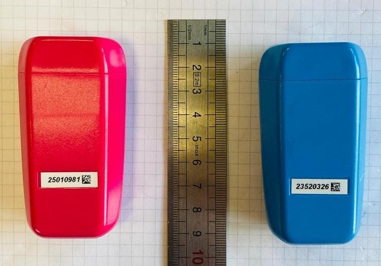
2BSNU-EFSV01SENO1
Dec 24, 2025The sensor analyzes the animals movements, detects birth, and sends an alert to the collector via the LoRa modem.
Equipment Class
DTS - Digital Transmission System
2BSNU-EFSV01CID01
Dec 24, 2025This product receives birth alerts from the sensor placed on the animal and sends a text message or voice message to the farmer.
Equipment Class
DTS - Digital Transmission System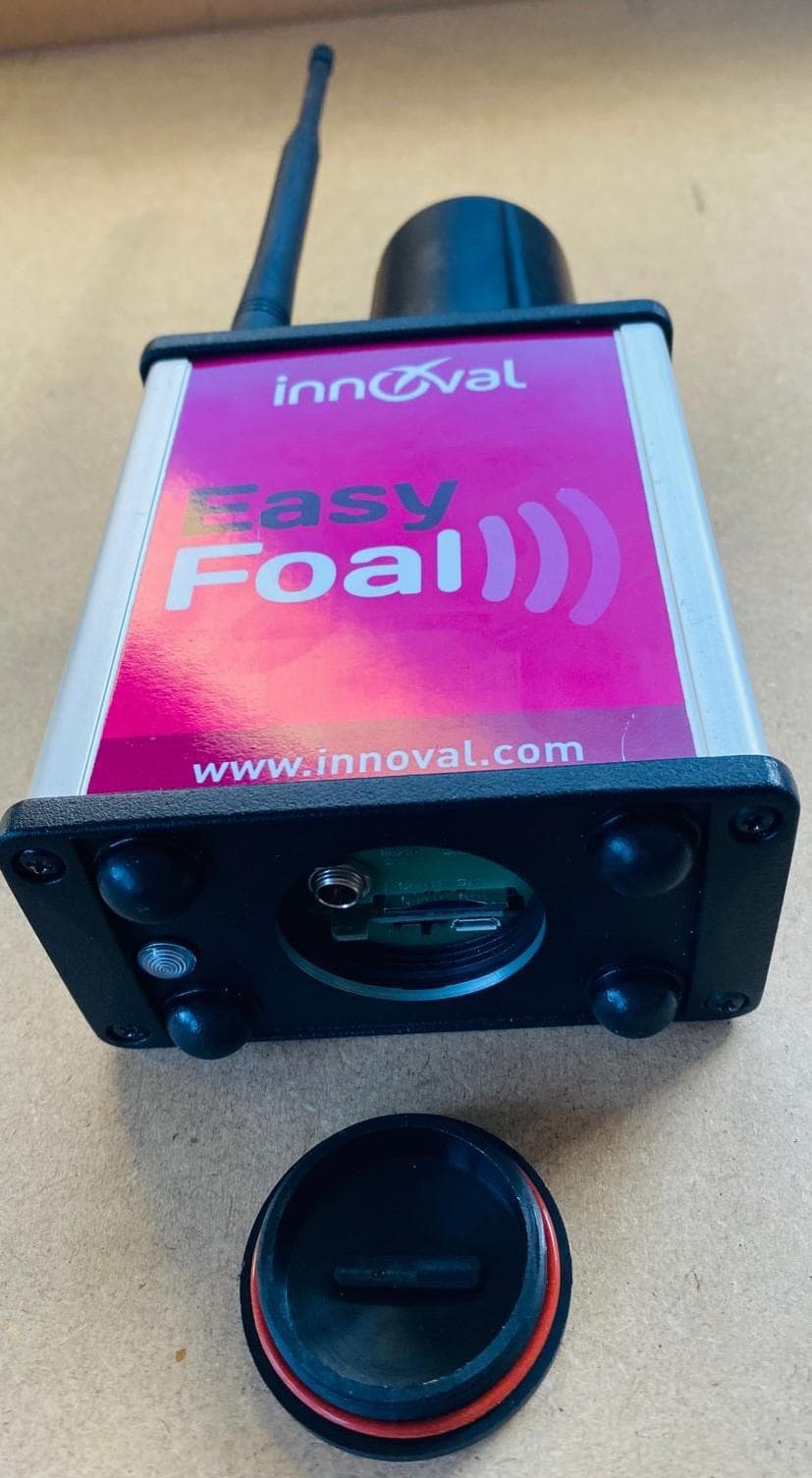
2BSNU-EFSV01COD01
Dec 23, 2025This product receives birth alerts from the sensor placed on the animal and sends a text message or voice message to the farmer.
Equipment Class
DTS - Digital Transmission System