2BUHQ-TXM3530wireless module
TECHXEN INC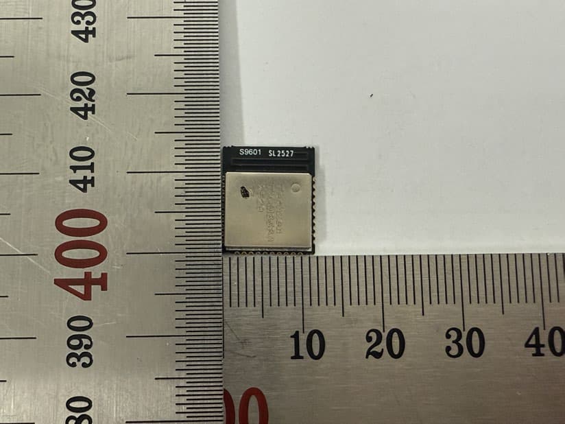
Click to zoom
Application Details
- Equipment Class
- DTS - Digital Transmission System
- Date of Grant
- Jan 28, 2026
- Application Purpose
- Original Equipment
- Equipment Note
- wireless module
- Frequency Range
- 2402.00000000 - 2480.00000000
- Company
- TECHXEN INC
- Country
- South Korea
Documents & Files
Document Text
Text extracted from the exhibit documents filed with the FCC. Open a document above to read the original.
Users Manual
1. Product Overview 1-1. Overview The TX-M3530 model is designed for wireless data transmission and reception under the Wi-Fi, BLE 2.4GHz communication standard, integrating an RF transceiver and on-board PCB antenna. 1-2. Features Product Manual 802.11 b/g/n/ax, BLE 2.4GHzWireless 2.8V ~ 3.6VVoltage UART Communication 2. Components 2-1. The TX-M3530 wireless module is supplied in tape-and-reel packaging. 3. Product Specifications Product Manual TX-M3530ModelName 14.0 x12.0 x 1.9 mmDimensions DC 3.3VPower Supply -30°C to+80°C OperatingTemperature UARTInterface 802.11 b/g/n/ax,BLEWirelessStandard 2.400 ~ 2.4835GHzFrequency Range: 11Channels, BLE : 40Channels Numberof Channels : On-BoardPCB PatternAntennaAntenna type: 4. User Manual 4-1. Pin Description DescriptionTypePin NamePin No. 3.3V Power SupplyPowerVDD12 GroundGroundGND1,11, 13, 30 UART TransmitI/OTXD6 UART ReceiveI/ORXD5 4-2. Operation description (1) Power the module by applying 3.3V to the VDD pin of the wireless module. (2) The module is controlled by a host microcontroller (MCU) via a UART interface. (3) Configure the module by sending commands via the TXD/RXD pins, Processing custom At commands. Product Manual Note : How to display the FCC ID Certification mark For very small devices, the mark may appear in the user manual TECHXEN INC TX-M3530 2529 KC FCC ID 2BUHQ-TXM3530 - 7 - FCC Compliance Statement This device complies with part 15 of the FCC rules. Operation is subject to the following two conditions: (1) This device may not cause harmful interference, and (2) this device must accept any interference received, including interference that may cause undesired operation. FCC Interference Statement This equipment has been tested and found to comply with the limits for a Class B digital device, pursuant to part 15 of the FCC Rules. These limits are designed to provide reasonable protection against harmful interference in a residential installation. This equipment generates, uses and can radiate radio frequency energy and, if not installed and used in accordance with the instructions, may cause harmful interference to radio communications. However, there is no guarantee that interference will not occur in a particular installation. If this equipment does cause harmful interference to radio or television reception, which can be determined by turning the equipment off and on, the user is encouraged to correct the interference by one of the following measures: • Reorient or relocate the receiving antenna. • Increase the separation between the equipment and receiver. • Connect the equipment into an outlet on a circuit different from which the receiver is connected. • Consult the dealer or an experienced radio/TV technician for help. FCC Caution Any changes or modifications not expressly approved by the party responsible for compliance could void the user's authority to operate this equipment. This transmitter must not be co-located or operating in conjunction with any other antenna or transmitter. End Product Labeling The module is labeled with its own FCC ID. If the FCC ID are not visible when the module is installed inside another device, then the outside of the device into which the module is installed must also display a label referring to the enclosed module. In that case, the final end product must be labeled in a visible area with the following: “Contains FCC ID: 2BUHQ-TXM3530 Information on test modes and additional testing requirements -OEM integrator is still responsible for testing their end-product for any additional compliance requirements required with this module installed (for example, digital device emissions, PC peripheral requirements, additional transmitter in the host, etc.). Additional testing, Part 15 Subpart B disclaimer -The final host product also requires Part 15 subpart B compliance testing with the modular transmitter installed to be properly authorized for operation as a Part 15 digital device.
Attestation Statements
TECHXEN INC 9th floor, N Tower Garden 26, Hwangsaeul-ro 200 beon-gil, Bundang-gu, Seongnam-si, Gyeonggi-do, South Korea Tel: +82-10-4201-4338 Federal Communications Commission Authorization and Evaluation Division 7435 Oakland Mills Road Columbia, MD 21046 USA Date: January 16, 2026 Regarding FCC Application (FCC ID: 2BUHQ-TXM3530) We, TECHXEN INC declare that the device does not support channel 12 ~ 13 in 2.4 GHz band. The firmware setting is not accessible by end users and/or unauthorized 3rd parties. Signature: seung yeon You / Engineering Manager TECHXEN INC
Attestation Statements
Applicant / Grantee TECHXEN INC / 2BUHQ FCC ID 2BUHQ-TXM3530 Section 15.212 Modular Transmitters Request for Modular Approval Request for Limited Modular Approval Requirements EUT Conditions Comply (Y/N) Single Modular Approval Requirements 1 The radio elements of the modular transmitter must have their own shielding. The physical crystal and tuning capacitors may be located external to the shielded radio elements. The radio elements of the modular transmitter are enclosed within a dedicated metal shield to prevent coupling. Y 2 The modular transmitter must have buffered modulation/data inputs (if such inputs are provided) to ensure that the module will comply with Part 15 requirements under conditions of excessive data rates or over- modulation. All modulation and data inputs are buffered through the onboard circuitry to ensure compliance under all conditions. Y 3 The modular transmitter must have its own power supply regulation.. The module incorporates its own internal voltage regulation to maintain compliance regardless of the host's power supply. Y 4 The modular transmitter must comply with the antenna and transmission system requirements of Sections 15.203, 15.204(b) and 15.204(c). The antenna must either be permanently attached or employ a “unique” antenna coupler (at all connections between the module and the antenna, including the cable). The “professional installation” provision of Section 15.203 is not applicable to modules but can apply to limited modular approvals under paragraph (b) of this section. The module incorporates an internal PCB pattern antenna that is permanently attached to the modular transmitter. This ensures that the antenna cannot be replaced or modified by the end-user, satisfying the requirements of Section 15.203. Y 5 The modular transmitter must be tested in a stand-alone configuration, i.e., the module must not be inside another device during testing for compliance with Part 15 requirements. Unless the transmitter module will be battery powered, it must comply with the AC line conducted requirements found in Section 15.207. AC or DC power lines and data input/output lines connected to the module must not contain ferrites, unless they will be marketed with the module (see Section 15.27(a)). The length of these lines shall be the length typical of actual use or, if that length is unknown, at least 10 centimeters The module was tested in a stand- alone configuration on a test fixture to demonstrate independent compliance. Y to insure that there is no coupling between the case of the module and supporting equipment. Any accessories, peripherals, or support equipment connected to the module during testing shall be unmodified and commercially available (see Section 15.31(i)). 6 The modular transmitter must be equipped with either a permanently affixed label or must be capable of electronically displaying its FCC identification number. (A) If using a permanently affixed label, the modular transmitter must be labeled with its own FCC identification number, and, if the FCC identification number is not visible when the module is installed inside another device, then the outside of the device into which the module is installed must also display a label referring to the enclosed module. This exterior label can use wording such as the following: “Contains Transmitter Module FCC ID: XYZMODEL1” or “Contains FCC ID: XYZMODEL1.” Any similar wording that expresses the same meaning may be used. The Grantee may either provide such a label, an example of which must be included in the application for equipment authorization, or, must provide adequate instructions along with the module which explain this requirement. In the latter case, a copy of these instructions must be included in the application for equipment authorization. (B) If the modular transmitter uses an electronic display of the FCC identification number, the information must be readily accessible and visible on the modular transmitter or on the device in which it is installed. If the module is installed inside another device, then the outside of the device into which the module is installed must display a label referring to the enclosed module. This exterior label can use wording such as the following: “Contains FCC certified transmitter module(s).” Any similar wording that expresses the same meaning may be used. The user manual must include instructions on how to access the electronic display. A copy of these instructions must be included Due to the module's small physical size, the FCC ID is displayed electronically in compliance with FCC regulations. Instructions for identifying this electronic identification are provided in the user manual. Y in the application for equipment authorization. 7 The modular transmitter must comply with any specific rules or operating requirements that ordinarily apply to a complete transmitter and the manufacturer must provide adequate instructions along with the module to explain any such requirements. A copy of these instructions must be included in the application for equipment authorization. Comprehensive instructions explaining the specific operational requirements are provided in the product's user manual. Y 8 The modular transmitter must comply with any applicable RF exposure requirements in its final configuration. The module complies with all applicable RF exposure requirements for its intended final configuration and usage. Y seung yeon You / Engineering Manager TECHXEN INC January 16, 2026
Attestation Statements
Rev 1/26/2023 TECHXEN INC Federal Communications Commission Authorization and Evaluation Division 7435 Oakland Mills Road Columbia, MD 21046 USA Date: 01-16-2026 Ref: Attestation Statements Part 2.911(d)(5)(i) Filing FCC ID: 2BUHQ-TXM3530 TECHXEN INC (“the applicant”) certifies that the equipment for which authorization is sought is not “covered” equipment prohibited from receiving an equipment authorization pursuant to section 2.903 of the FCC rules. TECHXEN INC (“the applicant”) certifies that the equipment for which authorization is sought does not include cybersecurity or anti-virus software produced or provided by Kaspersky Lab, Inc. or any of its successors and assignees, including equipment with integrated Kaspersky Lab, Inc. (or any of its successors and assignees) cybersecurity or anti-virus software pursuant to DA-24-886 and KDB 986446 D01 Covered Equipment Guidance section B(2a). Device is inherently compliant based on hardware limitations or software controls. or A Software Bill of Materials (SBOM) is provided to the TCB for review, and The end-user or third parties cannot install additional software on this device. Sincerely, Engineering Manager / seung yeon You TECHXEN INC Rev 1/26/2023 TECHXEN INC Federal Communications Commission Authorization and Evaluation Division 7435 Oakland Mills Road Columbia, MD 21046 USA Date: 01-16-2026 Ref: Attestation Statements Part 2.911(d)(5)(ii) Filing FCC ID: 2BUHQ-TXM3530 TECHXEN INC (“the applicant”) certifies that, as of the date of the filing of the application, the applicant is not identified on the Covered List (as a specifically named entity or any of its subsidiaries or affiliates) as an entity producing “covered” equipment. Sincerely, Engineering Manager / seung yeon You TECHXEN INC
Attestation Statements
TECHXEN INC 9th floor, N Tower Garden 26, Hwangsaeul-ro 200 beon-gil, Bundang-gu, Seongnam-si, Gyeonggi-do, South Korea Tel: +82-10-4201-4338 Federal Communications Commission Authorization and Evaluation Division 7435 Oakland Mills Road Columbia, MD 21046 USA Date: January 16, 2026 Ref: Attestation Statements Part 2.911(d)(7) Filing FCC ID: 2BUHQ-TXM3530 Applicant FRN : 0037894680 TECHXEN INC certifies that, as of the date of the filing of the application, FCC US AGENT, LLC. is our designated U.S. agent for service of process for the above referenced FCC ID. TECHXEN INC accepts to maintain an agent for no less than one year after the grantee has terminated all marketing and importation or the conclusion of any Commission-related proceeding involving the equipment. FCC US AGENT, LLC. accepts, as of the date of the filing of the application, the obligation of the designated U.S. agent for service of process for the above referenced FCC ID. Designated U.S. Agent Information: Company Name: FCC US Agent, LLC FRN: 0033402884 Address: 3722 Illinois Avenue, Saint Charles, IL, 60174, USA Contact Person: Tim Payne Phone: 708-571-3148 Email: [email protected] Sincerely, TECHXEN INC FCC US AGENT, LLC. Engineering Manager / seung yeon You Tim Payne [U.S. Agent signature] Rev 1/26/2023
Cover Letter(s)
TECHXEN INC 9th floor, N Tower Garden 26, Hwangsaeul-ro 200 beon-gil, Bundang-gu, Seongnam-si, Gyeonggi-do, South Korea +82-10-4201-4338 Date: January 16, 2026 Federal Communications Commission Authorization and Evaluation Division Confidentiality Request regarding application for certification of FCC ID: 2BUHQ-TXM3530 Pursuant to Sections 0.457 and 0.459 of the Commission’s Rules, we hereby request confidential treatment of information accompanying this application as outlined below: PERMANENT Exhibit Type File Name Part List Part List.pdf Schematics Diagram(s) Schematics.pdf Operation description Operational Description.pdf Block diagram Block diagram.pdf And the above materials contain trade secrets and proprietary information not customarily released to the public. The public disclosure of these materials may be harmful to the applicant and provide unjustified benefits to its competitors. The applicant understands that pursuant to Section 0.457 of the Rules, disclosure of this application and all accompanying documentation will not be made before the date of the Grant for this application. Sincerely, Engineering Manager / seung yeon You TECHXEN INC
Cover Letter(s)
TECHXEN INC 9th floor, N Tower Garden 26, Hwangsaeul-ro 200 beon-gil, Bundang-gu, Seongnam-si, Gyeonggi-do, South Korea Tel: +82-10-4201-4338 Date: January 16, 2026 Model : TX-M3530 To whom it may concern: I, the undersigned, hereby authorize Young-Jin, Lee of KES Co., Ltd. and hereafter referred to as KES Co., Ltd., to act on our behalf in all manners relating to application for equipment authorization, including signing of all documents relating to these matters. Any and all acts carried out by Young-Jin, Lee of KES Co., Ltd. on our behalf shall have the same effect as acts of our own. In authorizing KES Co., Ltd. as our agent, we still recognize that we are responsible to: a) comply with the relevant provisions of the certification program; b) make all necessary arrangements for the conduct of the evaluation, including provision for examining documentation and access to all areas, records (including internal audit reports) and personnel for the purposes of evaluation (e.g. testing, inspection, assessment, surveillance, reassessment) and resolution of complaints; c) make claims regarding certification only in respect of the scope for which certification has been granted; d) do not use our product certification in such a manner as to bring the Certification Division into disrepute and not make any statement regarding our product certification which the Certification Division may consider misleading or unauthorized; e) upon suspension or cancellation of certification, discontinue use of all advertising matter that contains any reference thereto and return any certification documents as required by the Certification Division; f) use certification only to indicate the products are certified as being in conformity with specified standards; g) endeavor to ensure that no certificate or report nor any part thereof is used in a misleading manner; h) ensure that any reference to our product certification in communication media such as documents, brochures or advertising, complies with the requirements of the Certification Division; i) keep a record of all complaints made known to the us relating to the product’s compliance with requirements of the relevant standard and to make these records available to the Certification Division when requested; TECHXEN INC 9th floor, N Tower Garden 26, Hwangsaeul-ro 200 beon-gil, Bundang-gu, Seongnam-si, Gyeonggi-do, South Korea Tel: +82-10-4201-4338 j) take appropriate action with respect to such complaints and any deficiencies found in products or services that affect compliance with the requirements for certification; k) document the actions taken. This authorization is valid until further written notice from the applicant. Sincerely Yours, seung yeon You / Engineering Manager TECHXEN INC
External Photos
FCC ID : 2BUHQ-TXM3530 Page 1 of 1 External photos
ID Label/Location Info
FCC ID : 2BUHQ-TXM3530 Page 1 of 1 Label Location Label & Label The device is so small that it is not practicable to place the statement specified under 15.19 statement request, the information required by this paragraph shall be placed in a prominent location in the User’s Manual.
Internal Photos
FCC ID : 2BUHQ-TXM3530 Page 1 of 1 Internal photos
RF Exposure Info
FCC ID: 2BUHQ-TXM3530 Page 1 of 1 RF exposure According to 447498 D01 General RF Exposure Guidance v06 The 1-g and 10-g SAR test exclusion thresholds for 100 ㎒ to 6 ㎓ at test separation distances ≤ 50 mm are determined by: [(max. power of channel, including tune-up tolerance, mW)/(min. test separation distance, mm)] ·[√f(㎓)] ≤ 3.0 for 1-g SAR and ≤ 7.5 for 10-g extremity SAR, Where; f(㎓) is the RF channel transmit frequency in ㎓ Power and distance are rounded to the nearest ㎽ and mm before calculation The result is rounded to one decimal place for comparison Results Mode Frequency (㎓) Distance (mm) Max Average tune-up power (㏈m) Calculation value Exclusion Threshold (㏈m) (㎽) LE 1 Mbps 2.402 ~ 2.480 5 9.00 7.943 2.502 ≤3.0 LE 2 Mbps 2.402 ~ 2.480 5 9.00 7.943 2.502 802.11b 2.412 ~ 2.462 5 9.00 7.943 2.493 802.11g 2.412 ~ 2.462 5 9.00 7.943 2.493 802.11n_HT20 2.412 ~ 2.462 5 9.00 7.943 2.493 802.11ax_HE20 2.412 ~ 2.462 5 9.00 7.943 2.493 802.11n_HT40 2.422 ~ 2.452 5 9.00 7.943 2.488
Test Report
Report No. : KES-RF250848 Page72/91 KES-QP16-F01(00-23-01-01)KES Co., Ltd. You can check the authenticity of this test report on our website (www.kes.co.kr). 3.5.Conducted spurious emissions & band edge Test setup EUTAttenuator Spectrum analyzer Test procedure Band edge For FCC, ANSI C63.10-2020 - Section 11.11 For IC, ANSI C63.10-2020 + Cor. 1-2023+C63.10a-2024 + Errata to C63.10a-2024 - Section 11.11 1.Start and stop frequency were set such that the band edge would be placed in the center of the plot 2.Span was set large enough so as to capture all out of band emissions near the band edge 3.Set the RBW = 100㎑ 4.Set the VBW = [3 × RBW]. 5.Detector = Peak 6.Sweep time = auto 7.Trace mode = max hold 8.Allow trace to fully stabilize. Out of band emissions For FCC, ANSI C63.10-2020 - Section 11.11 For IC, ANSI C63.10-2020 + Cor. 1-2023+C63.10a-2024 + Errata to C63.10a-2024 - Section 11.11 1.Start frequency was set to 30㎒and stop frequency was set to 25㎓for 2.4㎓frequencies and 40㎓for 5㎓frequencies 2.Set the RBW = 100㎑ 3.Set the VBW = [3 × RBW]. 4.Detector = Peak 5.Sweep time = auto 6.Trace mode = max hold 7.Allow trace to fully stabilize. Limit According to 15.247(d), in any 100㎑bandwidth outside the frequency band in which the spread spectrum or digitally modulated intentional radiator is operating, the radio frequency power that is produced by the intentional radiator shall be at least 20㏈below that in the 100㎑bandwidth within the band that contains the highest level of the desired power, based on either an RF conducted or a radiated measurement, provided the transmitter demonstrates compliance with the peak conducted power limits. If the transmitter complies with the conducted power limits based on the use of RMS averaging over a time interval , as permitted under paragraph(b)(3) of this section , the attenuation required under this paragraph shall be 30㏈ instead of 20㏈. Attenuation below the general limits specified in section 15.209(a) is not required. In addition, radiated emission which in the restricted band, as define in section 15.205(a), must also comply the radiated emission limits specified in section 15.209(a) (see section 15.205(c)) Report No. : KES-RF250848 Page73/91 KES-QP16-F01(00-23-01-01)KES Co., Ltd. You can check the authenticity of this test report on our website (www.kes.co.kr). Test results LE 1 Mbps 2 402㎒2 442㎒ Report No. : KES-RF250848 Page74/91 KES-QP16-F01(00-23-01-01)KES Co., Ltd. You can check the authenticity of this test report on our website (www.kes.co.kr). LE 1 Mbps 2 480㎒ Blank Report No. : KES-RF250848 Page75/91 KES-QP16-F01(00-23-01-01)KES Co., Ltd. You can check the authenticity of this test report on our website (www.kes.co.kr). LE 2 Mbps 2 402㎒2 442㎒ Report No. : KES-RF250848 Page76/91 KES-QP16-F01(00-23-01-01)KES Co., Ltd. You can check the authenticity of this test report on our website (www.kes.co.kr). LE 2 Mbps 2 480㎒ Blank Report No. : KES-RF250848 Page77/91 KES-QP16-F01(00-23-01-01)KES Co., Ltd. You can check the authenticity of this test report on our website (www.kes.co.kr). 802.11b 2 412㎒2 437㎒ Report No. : KES-RF250848 Page78/91 KES-QP16-F01(00-23-01-01)KES Co., Ltd. You can check the authenticity of this test report on our website (www.kes.co.kr). 802.11b 2 462㎒ Blank Report No. : KES-RF250848 Page79/91 KES-QP16-F01(00-23-01-01)KES Co., Ltd. You can check the authenticity of this test report on our website (www.kes.co.kr). 802.11g 2 412㎒2 437㎒ Report No. : KES-RF250848 Page80/91 KES-QP16-F01(00-23-01-01)KES Co., Ltd. You can check the authenticity of this test report on our website (www.kes.co.kr). 802.11g 2 462㎒ Blank Report No. : KES-RF250848 Page81/91 KES-QP16-F01(00-23-01-01)KES Co., Ltd. You can check the authenticity of this test report on our website (www.kes.co.kr). 802.11n_HT20 2 412㎒2 437㎒ Report No. : KES-RF250848 Page82/91 KES-QP16-F01(00-23-01-01)KES Co., Ltd. You can check the authenticity of this test report on our website (www.kes.co.kr). 802.11n_HT20 2 462㎒ Blank Report No. : KES-RF250848 Page83/91 KES-QP16-F01(00-23-01-01)KES Co., Ltd. You can check the authenticity of this test report on our website (www.kes.co.kr). 802.11ax_HE20 2 412㎒2 437㎒ Report No. : KES-RF250848 Page84/91 KES-QP16-F01(00-23-01-01)KES Co., Ltd. You can check the authenticity of this test report on our website (www.kes.co.kr). 802.11ax_HE20 2 462㎒ Blank Report No. : KES-RF250848 Page85/91 KES-QP16-F01(00-23-01-01)KES Co., Ltd. You can check the authenticity of this test report on our website (www.kes.co.kr). 802.11n_HT40 2 422㎒2 437㎒ Report No. : KES-RF250848 Page86/91 KES-QP16-F01(00-23-01-01)KES Co., Ltd. You can check the authenticity of this test report on our website (www.kes.co.kr). 802.11n_HT40 2 452㎒ Blank Report No. : KES-RF250848 Page87/91 KES-QP16-F01(00-23-01-01)KES Co., Ltd. You can check the authenticity of this test report on our website (www.kes.co.kr). 3.6.AC conducted emissions Limit According to 15.207(a), for an intentional radiator that is designed to be connected to the public utility (AC) power line, the radio frequency voltage that is conducted back onto the AC power line on any frequency or frequencies, within the band 150㎑to 30㎒, shall not exceed the limits in the following table, as measured using a 50uH/50 ohm line impedance stabilization network (LISN). Compliance with the provision of this paragraph shall on the measurement of the radio frequency voltage between each power line and ground at the power terminal. The lower applies at the boundary between the frequencies ranges. Frequency of Emission (㎒) Conducted limit (㏈㎶) Quasi-peakAverage 0.15 – 0.5066 - 56*56 - 46* 0.50 – 5.005646 5.00 – 30.06050 Report No. : KES-RF250848 Page88/91 KES-QP16-F01(00-23-01-01)KES Co., Ltd. You can check the authenticity of this test report on our website (www.kes.co.kr). Test results Mode:LE 2 Mbps Distance of measurement:3 meter Channel:39 (Worst case) Hot Line Neutral Line Report No. : KES-RF250848 Page89/91 KES-QP16-F01(00-23-01-01)KE…
Text truncated - open the document above for the full version.
Test Report
TEST REPORT Report No. : KES-RF250848 Page1/91 KES Co., Ltd. #3002, #3503, #3701, 40, Simin-daero365beon-gil, Dongan-gu, Anyang-si,Gyeonggi-do, 14057, Republic ofKorea Tel : +82-31-425-6200, Fax : +82-31-341-3838 KES-QP16-F01(00-23-01-01)KES Co., Ltd. You can check the authenticity of this test report on our website (www.kes.co.kr). FCC TEST REPORT 1. Client ○ Name : TECHXEN INC ○ Address : 9th floor, N Tower Garden 26, Hwangsaeul-ro 200 beon-gil, Bundang-gu, Seongnam-si, Gyeonggi-do, South Korea 2. Sample Description ○ Product item : wireless module ○ Model name : TX-M3530 ○ Manufacturer etc. : TECHXEN INC 3. Date of test :2026.01.05 ~ 2026.01.09 4. Location of Test :Permanent Testing LabOn Site Testing ○ Address : 473-21, Gayeo-ro, Yeoju-si, Gyeonggi-do, 12658, Rep. of Korea 5. FCC Rule part(s) :Part 15 Subpart C 15.247 6. Test result :PASS The results shown in this test report refer only to the sample(s) tested unless otherwise stated. This test report cannot be reproduced and copied without permission without the written consent of KES Co., Ltd. This laboratory is not accredited for the test results marked *. This test report is not related to KOLAS accreditation. Affirmation Tested byTechnical Manager Name : Myeong-Ho, Lee(Signature) Name :Yeong-Jun Cho(Signature) 2026. 01. 21. KES Co., Ltd. Report No. : KES-RF250848 Page2/91 KES-QP16-F01(00-23-01-01)KES Co., Ltd. You can check the authenticity of this test report on our website (www.kes.co.kr). REPORT REVISION HISTORY DateTest Report No.Revision History 2026.01.21KES-RF250848Initial This report shall not be reproduced except in full, without the written approval of KES Co., Ltd. This document may be altered or revised by KES Co., Ltd. personnel only, and shall be noted in the revision section of the document. Any alteration of this document not carried out by KES Co., Ltd. will constitute fraud and shall nullify the document. Report No. : KES-RF250848 Page3/91 KES-QP16-F01(00-23-01-01)KES Co., Ltd. You can check the authenticity of this test report on our website (www.kes.co.kr). TABLE OF CONTENTS 1.General information ................................................................................................................................... 4 1.1.EUT description .......................................................................................................................... 4 1.2.Test configuration........................................................................................................................ 4 1.3.Information about derivative model ............................................................................................ 5 1.4.Accessory information ................................................................................................................ 5 1.5.Device modifications................................................................................................................... 5 1.6.Sample calculation ..................................................................................................................... 5 1.7.Worst case data rate................................................................................................................... 5 1.8.Measurement Uncertainty .......................................................................................................... 5 1.9.Frequency/channel operations ................................................................................................... 6 2.Summary of tests ....................................................................................................................................... 7 3.Test results ................................................................................................................................................. 8 3.1.6㏈bandwidth .......................................................................................................................... 8 3.2.Output power ............................................................................................................................ 16 3.3.Power spectral density ............................................................................................................. 18 3.4.Radiated restricted band and emissions .................................................................................. 26 3.5.Conducted spurious emissions & band edge ........................................................................... 72 3.6.AC conducted emissions .......................................................................................................... 87 3.7.Antenna Requirement............................................................................................................... 90 Appendix A. Measurement equipment.......................................................................................................... 91 Report No. : KES-RF250848 Page4/91 KES-QP16-F01(00-23-01-01)KES Co., Ltd. You can check the authenticity of this test report on our website (www.kes.co.kr). 1.General information Applicant:TECHXEN INC Applicant address:9th floor, N Tower Garden 26, Hwangsaeul-ro 200 beon-gil, Bundang-gu, Seongnam-si, Gyeonggi-do, South Korea Test site:KES Co., Ltd. Test site address:#3002, #3503, #3701, 40, Simin-daero365beon-gil, Dongan-gu, Anyang-si, Gyeonggi-do, 14057, Rep. of Korea 473-21, Gayeo-ro, Yeoju-si, Gyeonggi-do, 12658, Rep. of Korea Test FacilityFCC Accreditation Designation No.: KR0100, Registration No.: 444148 FCC rule part(s):15.247 FCC ID:2BUHQ…
Text truncated - open the document above for the full version.
Contact Information
Applicant
seung yeon You
[email protected]Fax: 82316245527
Technical Contact
FCC US Agent, LLCTim Payne
3722 Illinois Avenue · Saint Charles, Illinois, 60174 · United States
Test Firm
KES Co., LtdInsung Ryu
[email protected]Fax: 82-31-424-0450
Technical Specifications
| # | Rule Parts | Frequency Range | Power Output |
|---|---|---|---|
| 1 | 15C | 2.40 GHz - 2.48 GHz | 8.49 mW |
| 2 | 15C | 2.41 GHz - 2.46 GHz | 99.54 mW |
Other Applications from TECHXEN INC
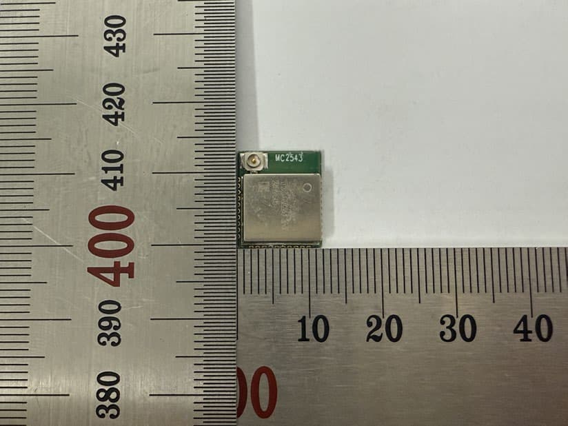
2BUHQ-TXM2830
Jan 28, 2026wireless module
Equipment Class
DTS - Digital Transmission System