2BUU2B0EMCB08B0EMCB08 Real Time Ethernet
tmeic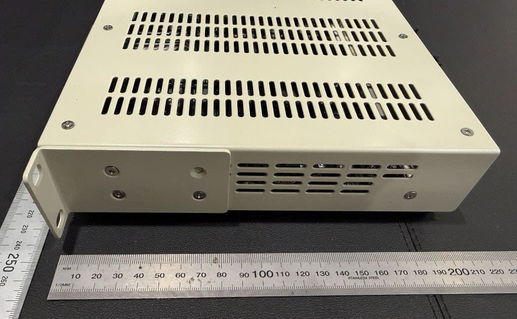
Click to zoom
Application Details
- Equipment Class
- JAD - Part 15 Class A Digital Device
- Date of Grant
- Mar 16, 2026
- Application Purpose
- Original Equipment
- Equipment Note
- B0EMCB08 Real Time Ethernet
- Company
- tmeic
- Country
- Australia
Documents & Files
Document Text
Text extracted from the exhibit documents filed with the FCC. Open a document above to read the original.
Attestation Statements
Rev 09/02/2026 Federal Communications Commission Authorization and Evaluation Division 7435 Oakland Mills Road Columbia, MD 21046 USA Date: Feb 16 th , 2026 Ref: Attestation Statements Part 2.911(d)(5)(i) Filing FCC ID: 2BUU2B0EMCB08 TMEIC Process Technology Application Centre Pty Ltd (“the applicant”) certifies that the equipment for which authorization is sought is not “covered” equipment prohibited from receiving an equipment authorization pursuant to section 2.903 of the FCC rules. TMEIC Process Technology Application Centre Pty Ltd (“the applicant”) certifies that the equipment for which authorization is sought does not include cybersecurity or anti-virus software produced or provided by Kaspersky Lab, Inc. or any of its successors and assignees, including equipment with integrated Kaspersky Lab, Inc. (or any of its successors and assignees) cybersecurity or anti-virus software pursuant to DA-24-886 and KDB 986446 D01 Covered Equipment Guidance section B(2a). Device is inherently compliant based on hardware limitations or software controls. or A Software Bill of Materials (SBOM) is provided to the TCB for review, and The end-user or third parties cannot install additional software on this device. Sincerely, Rodolfo Sandonato Engineering Manager TMEIC PROCESS TECHNOLOGY APPLICATION CENTRE PTY LTD Toshiba Mitsubishi-Electric Industrial Systems Corporation PO Box 688, Mornington VIC 3931 Australia 358 Main Street, Mornington VIC 3931 Australia Tel: +61(0) 3 5977 0722 Fax: +61(0) 3 5977 0833 Mob: +61(0) 428 459 130 [email protected] https://www.tmeic.com/ Rev 09/02/2026 Federal Communications Commission Authorization and Evaluation Division 7435 Oakland Mills Road Columbia, MD 21046 USA Date: Feb 16 th , 2026 Ref: Attestation Statements Part 2.911(d)(5)(ii) Filing FCC ID: 2BUU2B0EMCB08 TMEIC Process Technology Application Centre Pty Ltd (“the applicant”) certifies that, as of the date of the filing of the application, the applicant is not identified on the Covered List as an entity producing “covered” equipment. Sincerely, Rodolfo Sandonato Engineering Manager TMEIC PROCESS TECHNOLOGY APPLICATION CENTRE PTY LTD Toshiba Mitsubishi-Electric Industrial Systems Corporation PO Box 688, Mornington VIC 3931 Australia 358 Main Street, Mornington VIC 3931 Australia Tel: +61(0) 3 5977 0722 Fax: +61(0) 3 5977 0833 Mob: +61(0) 428 459 130 [email protected] https://www.tmeic.com/
Attestation Statements
Rev 02/04/2023 Certification designating a U.S. Agent for service of process: As required by section 2.911(d)(7), the applicant must designate a contact located in the United States for purposes of acting as the applicant’s agent for service of process, regardless of whether the applicant is a domestic or foreign entity. An applicant located in the United States may designate itself as the agent for service of process. In either scenario, the designation of the U.S. agent for service of process should be provided as an attachment to the equipment authorization application. The applicant must provide a written certification, which must: i. Be signed by both the applicant and designated agent for service of process, if the agent is different from the applicant. ii. Acknowledge the applicant’s consent and the designated agent’s obligation to accept service of process. iii. Provide a physical U.S. address and email for the designated agent. iv. Acknowledge the applicant’s acceptance to maintain an agent for no less than one year after the grantee has terminated all marketing and importation or the conclusion of any Commission-related proceeding involving the equipment. Unofficial information provided by FCC personnel on February 14, 2023, via the monthly call with the TCB Council: The Agent for Process of Service: • cannot be a TCB or affiliated with a TCB (e.g. could not be a person who works for a TCB or a company that owns or is owned by the TCB) • cannot be a [FCC recognised] Lab or affiliated with a test lab (e.g. could not be a person who works for a Lab or a company that owns or is owned by the Lab) • Agent can be Individual Entity or a Company Entity • Agent Entity must be located in US, US address/phone • Entity acting as Agent must have FRN (best practice, put FRN on Agent Letter) • Agent letter does not have to be FCC ID specific, can be general Agent for Grantee For devices being marketed or for which marketing has ceased for less than 1 year, if the Agent for Process of Service changes, then for every TC Number the TCB must request the FCC to put application into Audit Mode and Agent Letter needs to be updated (superseded). NOTE: The U.S. Agent for Service of Process should not be confused with the authorized agent used for signing the 731 form, other cover letters within the application, and/or the agent who may interface with the TCB. Rev 02 /04/2023 U.S. Agent Designation for Service of Process ATTENTION: Federal Communications Commission Authorization and Evaluation Division 7435 Oakland Mills Road Columbia, MD 21046 USA REGARDING: FCC Certification – Sectio n 2.911(d)(7) In formation D esignated U.S. Agent Company Name: Approve-IT, Inc . Contact Name: Nathan Grinager Street Address: 8011 34 th Ave South, Suite 342 City/Province/Zip: Bloomington, MN 55425 Telephone No: 651-247-1678 Email: [email protected] FRN #: 0027533835 This letter is t o confirm that we (“the Designated U.S. Agent) have accepted the responsibility to act as the Designated U.S. Agent for Service of Process as r equired by section 47 CFR 2.911(d)(7) on behalf of t he Applicant noted below. U.S. Agent Signature: Date: March 10, 2026 Signed by (Printed Name/Title): Nathan Grinager / Co-President The Applicant confirms its explicit consent and acknowledges that they must maintain an agent for no less than one year after terminating all marketing and importation OR the conclusion of any Commission-related proceeding involving the equipment. The applicant further acknowledges their responsibility to inform the FCC whenever the Designated U.S. Agent information above changes. Appli cant Company name: TMEIC PROCESS TECHNOLOGY APPLICATION CENTRE PTY LTD FCC ID: 2BUU2B0EMCB08 Contact Name: Rodolfo Sandonato Street Address: 358 Main Street City/Province/Zip: Mornington 3931, Victoria, Australia Telephone No: +6159770722 Email: [email protected] Appli cant Signature: Date : 10th/Mar/2026 Signe d by (Printed Name/Title): Mr. Rodolfo Sandonato / Engineering Manager
Cover Letter(s)
Rev 11/20/07 Federal Communications Commission Date: Feb 23 rd , 2026 Authorization and Evaluation Division Confidentiality Request regarding application for certification of FCC ID: 2BUU2B0EMCB08. Pursuant to Sections 0.457 and 0.459 of the Commission’s Rules, we hereby request confidential treatment of information accompanying this application as outlined below: Exhibit Type File Name Schematics: Block diagrams: Data sheet/Op Description: 2BUU2B0EMCB08_Schematic.PDF 2BUU2B0EMCB08_DP-3750_Block_Diagram.pdf 2BUU2B0EMCB08_DT-3484_Operational_Description.pdf The above materials contain trade secrets and proprietary information not customarily released to the public. The public disclosure of these materials may harm the applicant and confer unjustified benefits on its competitors. The applicant understands that pursuant to Section 0.457 of the Rules, disclosure of this application and all accompanying documentation will not be made before the date of the Grant for this application. Pursuant to DA04-1705 June 15, 2004, of the Commission’s public notice, we also request temporary confidential treatment of information accompanying this application as outlined below for 90 days : Exhibit Type File Name User/ Installation Manual: 2BUU2B0EMCB08_UG-3502_User_Manual.pd Sincerely, Rodolfo Sandonato Engineering Manager TMEIC PROCESS TECHNOLOGY APPLICATION CENTRE PTY LTD Toshiba Mitsubishi-Electric Industrial Systems Corporation PO Box 688, Mornington VIC 3931 Australia 358 Main Street, Mornington VIC 3931 Australia Tel: +61(0) 3 5977 0722 Fax: +61(0) 3 5977 0833 Mob: +61(0) 428 459 130 [email protected] https://www.tmeic.com/
External Photos
PN912 Photos RAS (TMEIC 05-Feb-2026 Page 1 of 4 1.1 External Photos Figure 1 – PN912 Front View Figure 2 – PN912 Rear View Long PN912 Photos RAS (TMEIC 05-Feb-2026 Page 2 of 4 Figure 3 – PN912 Front View Long Bracket Figure 4 – PN912 Rear View Long Bracket PN912 Photos RAS (TMEIC 05-Feb-2026 Page 3 of 4 Figure 5 – PN912 Right Side View Figure 6 – PN912 Left Side View PN912 Photos RAS (TMEIC 05-Feb-2026 Page 4 of 4 Figure 7 – PN912 Bottom View – Labels and Accessories Figure 8 – PN912 Top View and Accessories
Internal Photos
PN912 Photos RAS (TMEIC 05-Feb-2026 Page 1 of 7 1.1 Internal Photos Figure 1 – PN912 Internal Front View PN912 Photos RAS (TMEIC 05-Feb-2026 Page 2 of 7 1.2 Figure 2 – PN912 Internal Main Board PN912 Photos RAS (TMEIC 05-Feb-2026 Page 3 of 7 Figure 3 – PN912 Internal Front View PN912 Photos RAS (TMEIC 05-Feb-2026 Page 4 of 7 Figure 4 – PN912 Internal Top View PN912 Photos RAS (TMEIC 05-Feb-2026 Page 5 of 7 Figure 5 – PN912 Internal Left View PN912 Photos RAS (TMEIC 05-Feb-2026 Page 6 of 7 Figure 6 – PN912 Internal Right View PN912 Photos RAS (TMEIC 05-Feb-2026 Page 7 of 7 Figure 7 – PN912 Internal View & Accessories
Test Report
The results detailed in this test report relate only to the specific sample/s tested. It is the Manufacturer’s responsibility to ensure that all production units are manufactured with equivalent EMC characteristics. This report is not to be reproduced except in full, without written approval from Compliance Engineering 90 Indian Drive Keysborough VIC 3173 Australia Telephone: + 61 3 9763 3079 Email: [email protected] Web: www.compeng.com.au ABN: 96 668 483 574 TMEIC Process Technology Application Centre P/L B0EMCB08 Real Time Ethernet Model: PN912 EMC Compliance Test Report CFR 47, Chapter 1, Subpart A, Part 15, Subpart B Report Number: CE4774B January 2026 Doc: 1.3 Compliance Engineering Test Report CE4774B, January 2026 Page 2 of 18 This test report is not to be reproduced except in full, without written approval from Compliance Engineering . 90 Indian Drive, Keysborough, Victoria 3173. Australia Telephone: +61 3 9763 3079 Email: [email protected] Web: www.compeng.com.au COMPLIANCE CERTIFICATE Client Details: Customer: TMEIC Process Technology Application Centre P/L Address: 358 Main Street, Mornington, Victoria 3931 Australia Contact: Rodolfo Sandonato Phone: 03 5977 0722 / 0428 459 130 Email: [email protected] Product Details: Device: Model: Serial: B0EMCB08 Real Time Ethernet PN912 PN912c-005 2BUU2B0EMCB08 Reference Standard: FCC Part 15 B CFR 47 - Telecommunication Chapter I - Federal Communications Commission Subchapter A - General Part 15 - Radio Frequency Devices Subpart B Unintentional Radiators Test Method: ANSI C63.4-2014: American National Standard for Methods of Measurement of Radio-Noise Emissions from Low-Voltage Electrical and Electronic Equipment in the range of 9 kHz to 40 GHz. Test Dates: 13 th December 2025 Tests Performed by: Ahmed Ibrahim Compliance Engineering 90 Indian Drive, Keysborough, Victoria, Australia 3173. Telephone: +61 3 9763 3079 Email: [email protected] The B0EMCB08 Real Time Ethernet (Model: PN912) complied with radiated RF emission requirements detailed in CFR 47, Chapter 1, Subpart A, Part 15, Subpart B (Class A) limits. 23 rd January 2026 Prepared: Ahmed Ibrahim Test Engineer Compliance Engineering Approved: Matthew Grimwood EMC Laboratory Manager Compliance Engineering Date FCC ID: Doc: 1.3 Compliance Engineering Test Report CE4774B, January 2026 Page 3 of 18 This test report is not to be reproduced except in full, without written approval from Compliance Engineering . 90 Indian Drive, Keysborough, Victoria 3173. Australia Telephone: +61 3 9763 3079 Email: [email protected] Web: www.compeng.com.au Revision History Revision Issue Date Remarks Revised by 0 23-01-2026 Initial release - Doc: 1.3 Compliance Engineering Test Report CE4774B, January 2026 Page 4 of 18 This test report is not to be reproduced except in full, without written approval from Compliance Engineering . 90 Indian Drive, Keysborough, Victoria 3173. Australia Telephone: +61 3 9763 3079 Email: [email protected] Web: www.compeng.com.au Table of Contents 1. INTRODUCTION ......................................................................................................... 5 2. RESULTS SUMMARY ................................................................................................ 5 3. TEST SAMPLE ........................................................................................................... 5 4. MODIFICATIONS ........................................................................................................ 7 5. STANDARD DEVIATIONS .......................................................................................... 7 6. CONFIGURATION ...................................................................................................... 7 6.1. Supporting Equipment Used During Testing .................................................... 8 7. TEST FACILITY .......................................................................................................... 9 8. FIELD STRENGTH CALCULATION ......................................................................... 10 9. MEASUREMENT UNCERTAINTY ............................................................................ 11 10. AC CONDUCTED RF EMISSION MEASUREMENTS .............................................. 12 11. RADIATED RF EMISSION MEASUREMENTS......................................................... 12 11.1. REQUIREMENTS ........................................................................................... 12 11.2. TEST EQUIPMENT ........................................................................................ 12 11.3. ENVIRONMENTAL CONDITIONS ................................................................. 12 11.4. PROCEDURE ................................................................................................. 12 11.5. RESULTS ....................................................................................................... 15 11.6. ASSESSMENT ............................................................................................... 18 12. CONCLUSION .......................................................................................................... 18 Doc: 1.3 Compliance Engineering Test Report CE4774B, January 2026 Page 5 of 18 This test report is not to be reproduced except in full, without written approval from Compliance Engineering . 90 Indian Drive, Keysborough, Victoria 3173. Australia Telephone: +61 3 9763 3079 Email: [email protected] Web: www.compeng.com.au EMC Compliance Test Report 1. INTRODUCTION Electromagnetic compatibility (EMC) measurements were performed on the B0EMCB08 Real Time Ethernet (Model: PN912) in accordance with the requirements detailed in CFR 47, Chapter 1, Subpart A, Part 15, Subpart B (Class A) limits. 2. RESULTS SUMMARY CFR 47, Chapter 1, Subpart A, Part 15, Subpart B FCC Rule Test Description Class Result 15.107 AC conducted emissions Class A N/A 15.109 Radiated emissions Complied N/A – Not Applicabl…
Text truncated - open the document above for the full version.
Test Setup Photos
The results detailed in this test report relate only to the specific sample/s tested. It is the Manufacturer’s responsibility to ensure that all production units are manufactured with equivalent EMC characteristics. This report is not to be reproduced except in full, without written approval from Compliance Engineering 90 Indian Drive Keysborough VIC 3173 Australia Telephone: + 61 3 9763 3079 Email: [email protected] Web: www.compeng.com.au ABN: 96 668 483 574 TMEIC Process Technology Application Centre P/L B0EMCB08 Real Time Ethernet Model: PN912 EMC Compliance Test Report CFR 47, Chapter 1, Subpart A, Part 15, Subpart B Report Number: CE4774B January 2026 Doc: 1.3 Compliance Engineering Test Report CE4774B, January 2026 Page 8 of 18 This test report is not to be reproduced except in full, without written approval from Compliance Engineering . 90 Indian Drive, Keysborough, Victoria 3173. Australia Telephone: +61 3 9763 3079 Email: [email protected] Web: www.compeng.com.au 6.1. Supporting Equipment Used During Testing AE: Auxiliary/Associated Equipment Device Manufacturer Model No: Serial Comments Real Time Ethernet Gateway TMEIC PN912 PN912c-004 Support Equipment for data logging PC N/A N/A TMWRK13 For ODG server data logging Doc: 1.3 Compliance Engineering Test Report CE4774B, January 2026 Page 14 of 18 This test report is not to be reproduced except in full, without written approval from Compliance Engineering . 90 Indian Drive, Keysborough, Victoria 3173. Australia Telephone: +61 3 9763 3079 Email: [email protected] Web: www.compeng.com.au Doc: 1.3 Compliance Engineering Test Report CE4774B, January 2026 Page 7 of 18 This test report is not to be reproduced except in full, without written approval from Compliance Engineering . 90 Indian Drive, Keysborough, Victoria 3173. Australia Telephone: +61 3 9763 3079 Email: [email protected] Web: www.compeng.com.au 4. MODIFICATIONS No modification was performed. 5. STANDARD DEVIATIONS No deviations from the standard were made. 6. CONFIGURATION The B0EMCB08 Real Time Ethernet (Model: PN912) was powered at 24VDC via two 12V batteries. The EUT (Serial: PN912c-005) was communicating with a companion unit (Serial: PN912c-004). A datalogging server (ODG) was used to capture all the activity. All the parameters listed below in the table were captured and recorded. Doc: 1.3 Compliance Engineering Test Report CE4774B, January 2026 Page 13 of 18 This test report is not to be reproduced except in full, without written approval from Compliance Engineering . 90 Indian Drive, Keysborough, Victoria 3173. Australia Telephone: +61 3 9763 3079 Email: [email protected] Web: www.compeng.com.au Plots of the accumulated measurement data, including all transducer correction factors were produced and stored to file. Measurements below 1 GHz: RWB = 120 kHz, VBW = 3 x RBW Measurements above 1 GHz: RF absorber is placed on the ground reference plane between the EUT and the measuring antenna and its location size should allow the test site area comply with the CISPR 16-1-4 requirements. RWB = 1 MHz (minimum), VBW = 3 x RBW Note: RF absorber is placed onto the horizontal ground reference plane only during measurements above 1 GHz Horizontal Ground Reference Plane 3m 0.8m Semi-Anechoic Shielded Enclosure (iOATS) – Table Top Turntable Non-conductive support EUT 1-4m RX Antenna Spectrum Analyser / Receiver Antenna reference point
Contact Information
Applicant
Rodolfo Sandonato
[email protected]Fax: 0359770722
Technical Contact
Approve-IT, Inc.Nathan Grinager
8011 34th Ave South · Bloomington, Minnesota, 55425 · United States
Test Firm
Compliance Engineering ServicesSimon Grilj
Technical Specifications
| # | Rule Parts | Frequency Range | Power Output |
|---|---|---|---|
| 1 | 15B | - | - |