2BVYH-UL01N1LoRaLink
Nube iO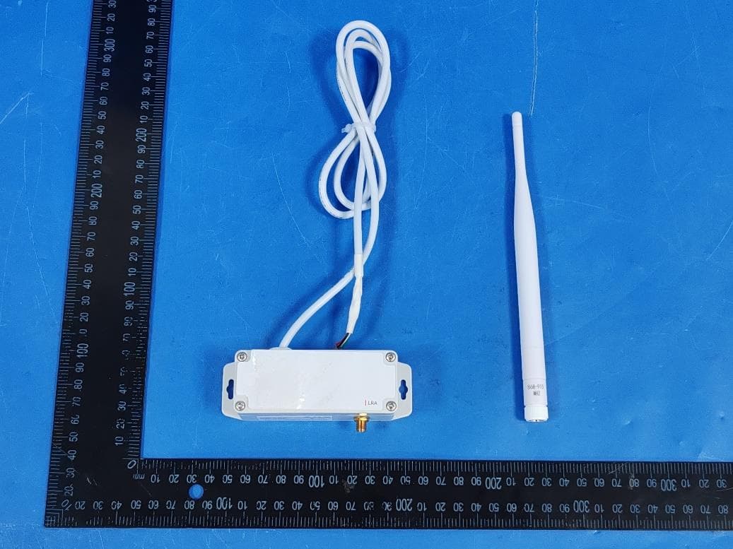
Click to zoom
Application Details
- Equipment Class
- DXX - Part 15 Low Power Communication Device Transmitter
- Date of Grant
- Sep 18, 2026
- Application Purpose
- Original Equipment
- Equipment Note
- LoRaLink
- Frequency Range
- 902.30000000 - 914.90000000
- Company
- Nube iO
- Country
- Australia
Documents & Files
Document Text
Text extracted from the exhibit documents filed with the FCC. Open a document above to read the original.
Users Manual
LoraLinkUART Long Range Adaptor (LRA) User Manual UART Long Range Adaptor (LRA) User Manual 1. About Product 1.1. Product Overview The UART Long Range Adaptor (LRA) is anywAiR iO’s wireless (LoRa®) Long Range Adaptor (LRA) controller. Designed to interface directly with compatible RAC/PAC and VRF Air Conditioning units in a small package, reducing the installation time and bypassing the AT command interface. LoRa® wireless IoT technology offers a long transmission range, low power consumption, and is less susceptible to object interference than other wireless technologies. This ensures seamless control integration for a range of applications. 1.2. Architecture Long Range Adaptor (LRA): Acts as the communication device, interfacing with compatible RAC/PAC and VRF Air Conditioning units via the UART protocal. It manages data transmission to and from the central anywAiR iO gateway. anywAiR iO Gateway: Serves as the central node, managing communication from multiple Long Range Adaptor (LRA) devices and distributing data as needed. Control: The Long Range Adaptor (LRA) device directly manages data exchange with compatible Air Conditioning units using their specific UART protocol. 1.3. Product Features Operation Control: Enable the unit on and off. Mode Control: Switch between cool, heat, dry, auto, and fan modes. Temperature Setpoint Control: Adjust heating/cooling temperature setpoint. Cooling setpoint 18 to 30 degrees Celsius Heating setpoint 16-18 to 30 degrees Celsius (low limit model dependent) Fan Speed Control: Control fan speed (model dependent). Louvre Direction Control: Adjust vertical and horizontal louvre position and louvre swing operation (model dependent). Economy Control: Enable and disable the unit's economy mode. Return Air Temperature Monitoring: Monitor the return air temperature. Error Status Reporting: Retrieve the error status and error code. 2. Hardware Overview 2.1. Packing List Installation & User Manual. UART Long Range Adaptor (LRA) Device LoRa Antenna. PAP-04V-S power/communication cable. Mounting screws/velcro tape. Insert Packing list images 2.2. Product Dimensions Height:36 mm / 1.42 inches Width:110 mm / 4.33 inches Depth:35 mm / 1.38 inches EnclosureLight Grey Polycarbonate, IP68 Rated 2.3. Product Component Breakdown 2.3.1 External U.FL Antenna Connector: Connects the antenna for wireless communication. Mounting Holes: Allows for secure mounting via appropriate fixings. Countersunk Screws: Allows for easy opening of the device. Nylon Bushing: Facilitates the entry of cables into the device. 2.3.2 Internal Reset Button: Pressing this button will reset the UART Long Range Adaptor (LRA), restart the firmware and publish a lora message. Boot Button: Used to enter the device into Boot mode for firmware updates LED Indicators: Used to indicate device operation status's. Red PWR light - When active indicates the device is powered. Green TX light - When periodically flashing indicates communication. Blue RX light - When periodically flashing indicates communicationn. Orange L1 light - Will be inactive in normal operation. If reset is pressed L1 will illuminate momentarily during the reboot cycle. Lora Connector: Connects the U.FL Antenna Connector to the internal PCB. USB-C Port: Provides a connection point to update the device firmware. CN Connector: Connection point for the PAP-04V-S Connector linking the Long Range Adaptor (LRA) to the Air Conditioner UART port (CN6, CN65 or CN75). PCB Screws: Used to secure the PCB in the enclosure. 3. Installation & Configuration 3.1. Mounting The UART Long Range Adaptor (LRA) can be mounted in several ways depending on the type of air conditioning system. In all cases, the antenna must remain vertical (unless specifically noted). The UART Long Range Adaptor (LRA) should always be mounted in a location such that it will not experience extreme high or low temperatures, liquids or high humidity. Use either the provided Velcro tape or fixings, depending on the surface and accessibility. General Notes Keep the antenna vertical and unobstructed for best signal performance. Use existing penetrations where possible to avoid damaging the air conditioning unit. Velcro tape is preferred where drilling may risk damage to internal components. Ensure the cable path is tidy, protected, and free from heat sources or moving parts. 3.1.1 Direct Mounting The UART Long Range Adaptor (LRA) can be mounted via fixings utilising the mounting clips depending on the type of air conditioning system and mounting location. Direct Mounting Process: 1. Position the UART Long Range Adaptor (LRA) against the mounting location & mark the fixing points. 2. Drill the holes & insert wall plugs if required. 3. Secure the UART Long Range Adaptor (LRA) using appropriate screws or fixings. 4. Gently pull forward to confirm it is firmly mounted. 3.1.2 Adhesive Mounting The UART Long Range Adaptor (LRA) can be mounted via adhesive velcro tape depending on the type of air conditioning system and mounting location. Adhesive Mounting Process: 1. Clean the mounting surface with a suitable cleaner to remove dust, grease, or other contaminants. 2. Peel the backing strips off one side of the Velcro pads and stick them to the back of the UART Long Range Adaptor (LRA) device. 3. Then, remove the remaining backing strips and press the UART Long Range Adaptor (LRA) firmly against the wall or surface where it will be mounted. Maintain firm pressure for approximately 30 seconds to ensure a strong bond. 3.3 Unit Mounting Locations The UART Long Range Adaptor (LRA) can be mounted in various locations depending on the type of air conditioning system. The following sections outline the recommended mounting locations for different system types. 3.3.1 Split Systems The UART Long Range Adaptor (LRA) can be mounted: On the unit — either at the bottom, top, or side of the outdoor case. On the wall next to the unit — horizontally or vertically. Inside trunking — above or beside cable penetra…
Text truncated - open the document above for the full version.
Attestation Statements
Rev 1/26/2023 Nube iO Federal Communications Commission Authorization and Evaluation Division 7435 Oakland Mills Road Columbia, MD 21046 USA Date: 2026-09-11 FCC ID: 2BVYH-UL01N1 Ref. #1: Attestation Statements Part 2.911(d)(5)(i) Filing Nube iO certifies that the equipment for which authorization is sought is not “covered” equipment prohibited from receiving an equipment authorization pursuant to section 2.903 of the FCC rules. Nube iO certifies that the equipment for which authorization is sought does not include cybersecurity or anti-virus software produced or provided by Kaspersky Lab, Inc. or any of its successors and assignees, including equipment with integrated Kaspersky Lab, Inc. (or any of its successors and assignees) cybersecurity or anti-virus software pursuant to DA-24-886 and KDB 986446 D01 Covered Equipment Guidance section B(2a). Device is inherently compliant based on hardware limitations or software controls. or A Software Bill of Materials (SBOM) is provided to the TCB for review, and The end-user or third parties cannot install additional software on this device. Ref. #2: Attestation Statements Part 2.911(d)(5)(ii) Filing Nube iO certifies that, as of the date of the filing of the application, the applicant is not identified on the Covered List (as a specifically named entity or any of its subsidiaries or affiliates) as an entity producing “covered” equipment. Applicant: Nube iO Address: 1/17 Cemetery Rd, Helensburgh, NSW 2508, Australia Contact Person: Hoai Hoang Tel.: +61 2 7906 8414 Email: [email protected] Sincerely, Signature:
Attestation Statements
Attestation Statements Date: 2026-09-11 TO: Federal Communications Commission Authorization and Evaluation Division 7435 Oakland Mills Road Columbia, MD 21046, USA RE: Attestation Statements Part 2.911(d)(7) request for(FCC ID: 2BVYH-UL01N1) Nube iO, the undersigned, hereby authorize FCC US Agent, LLC to act as our designated agent for service of process, Nube iO accepts to maintain an agent for no less than one year after the grantee has terminated all marketing and importation or the conclusion of any Commission- related proceeding involving the equipment. FCC US Agent, LLC accepts the responsibility to act as designated agent for service of process. Applicant Information: Company name: Nube iO Contact Name: Hoai Hoang Address: 1/17 Cemetery Rd, Helensburgh, NSW 2508, Australia Telephone No: +61 2 7906 8414 Email: [email protected] FRN: 0038385738 Signature: Hoai Hoang Agent Information: Company Name: FCC US Agent, LLC Address:3722 Illinois Avenue, Saint Charles, IL, 60174, USA FRN: 0033402884 Contact Name: Tim Payne Telephone No: 708-571-3148 Email: [email protected] Signature: Tim Payne
Cover Letter(s)
Nube iO Office of Engineering Technology Federal Communications Commission 7435 Oakland Mills Road Columbia, MD 21046 USA Date: September 11, 2026 Subject; Request for Confidentiality FCC ID: 2BVYH-UL01N1 To Whom It May Concern, Pursuant to the provisions of the Commission’s rules Title 47 Sections §0.457 and §0.459, we are requesting the Commission to withhold the following attachment(s) as confidential documents from public disclosure indefinitely. These documents contain detailed system and equipment descriptions and are considered as proprietary information in operation of the equipment. The public disclosure of these documents might be harmful to our company and would give competitors an unfair advantage in the market. Schematic Diagram Block Diagram Parts List Operational Description Tune-up Procedure SOFTWARE SECURITY REQUIREMENTS FOR U-NII DEVICES In additional to above mentioned documents, in order to comply with the marketing regulations in Title 47 CFR §2.803 and the importation rules in Title 47 CFR §2.1204, while ensuring that business sensitive information remains confidential until the actual marketing of newly authorized devices, we request Short Term Confidentiality of the following attachment(s); External Photos Test Setup Photos Internal Photos User Manual For 45 days, pursuant to Public Notice DA 04-1705. OR For 180 days pursuant to KDB 726920 D01. It is our understanding that all measurement test reports, FCC ID label format and correspondence during the certification review process cannot be granted as confidential documents and this information will be available for public review once the grant of equipment authorization is issued. Sincerely, Signature: Name: Hoai Hoang Title: Lead Hardware Design
Cover Letter(s)
Effective Date: April 2, 2020 QSF 7.6.4-8 – Agent Authorization Letter Template Page 1 of 1 Revision Date: Revision: 0 Nube iO Date:2026-09-11 Product Model Number: UL-01-N1 FCC ID:2BVYH-UL01N1 To whom it may concern, Re: Product Certification Representative Authorization Letter We authorize QAI Laboratories Ltd. 3980 North Fraser Way, Burnaby B.C. Canada V5J 5K5 to act on our behalf on all matters concerning the above named equipment. This shall include the following: • Testing • Approval applications and procedures We declare that QAI Laboratories Ltd. is allowed to forward all information related to the approval project to the applied certification body and to the notification entities and to discuss any issues concerning the approval application. Any and all acts carried out by QAI Laboratories Ltd. on our behalf shall have the same effect as acts of our own. Signature: By: Hoai Hoang Contact Listed on FCC Wesbite Title: Lead Hardware Design Email: [email protected] On behalf of: Nube iO
External Photos
Page 1 of 4 Report No.: LGT25L403 Appendix - External Photographs of EUT Constructional Details Photo 1 Photo 2 Page 2 of 4 Report No.: LGT25L403 Appendix - External Photographs of EUT Constructional Details Photo 3 Photo 4 Page 3 of 4 Report No.: LGT25L403 Appendix - External Photographs of EUT Constructional Details Photo 5 Photo 6 Page 4 of 4 Report No.: LGT25L403 Appendix - External Photographs of EUT Constructional Details Photo 7 Photo 8 LoRa ANT
ID Label/Location Info
Label Size: 40mm*16mm FCC ID: 2BVYH-UL01N1
Internal Photos
Page 1 of 4 Report No.: LGT25L403 Appendix - Internal Photographs of EUT Constructional Details Photo 1 Photo 2 Page 2 of 4 Report No.: LGT25L403 Appendix - Internal Photographs of EUT Constructional Details Photo 3 Photo 4 Page 3 of 4 Report No.: LGT25L403 Appendix - Internal Photographs of EUT Constructional Details Photo 5 Photo 6 Page 4 of 4 Report No.: LGT25L403 Appendix - Internal Photographs of EUT Constructional Details Photo 7
RF Exposure Info
The test report is effective only with both signature and specialized stamp. This report shall not be reproduced except in full without the written approval of the Laboratory. The results in this report only apply to the tested sample. Shenzhen LGT Test Service Co., Ltd. Tel: 0755-89668180 E-mail:[email protected] Web: www.lgt-cert.com Room 205, Building 13, Zone B, Zhenxiong Industrial Park, No.177, Renmin West Road, Jinsha, Kengzi Street, Pingshan District, Shenzhen, Guangdong, China Page 1 of 8 EMF TEST REPORT Product Name: LoRaLink Model Number: UL-01-N1 FCC ID: 2BVYH-UL01N1 Issued For : Nube iO 1/17 Cemetery Rd, Helensburgh, NSW 2508, Australia Issued By : Shenzhen LGT Test Service Co., Ltd. Room 205, Building 13, Zone B, Zhenxiong Industrial Park, No.177, Renmin West Road, Jinsha, Kengzi Street, Pingshan District, Shenzhen, Guangdong, China Report Number: LGT25L403HA02 Sample Received Date: Dec. 22, 2025 Date of Test: Mar. 05, 2026 ~ Jul. 04, 2026 Date of Issue: Jul. 04, 2026 Report No.: LGT25L403HA02 Page 2 of 8 TEST REPORT CERTIFICATION Applicant: Nube iO Address: 1/17 Cemetery Rd, Helensburgh, NSW 2508, Australia Manufacturer: Shenzhen Elecrow Co.,ltd Address: 4-5th Floor, Building B,Nanchang Huafeng Industrial Park, Baoan District, Shenzhen, China 518126 Product Name: LoRaLink Trademark: N/A Model Number: UL-01-N1 Sample Status: Normal APPLICABLE STANDARDS STANDARD TEST RESULTS FCC 47 CFR §2.1091 KDB 447498 D01 General RF Exposure Guidance v06 PASS Prepared by: Approved by: Zane Shan Vita Li Engineer Technical Director Report No.: LGT25L403HA02 Page 3 of 8 TABLE OF CONTENTS 1 . GENERAL INFORMATION 5 1.1 GENERAL DESCRIPTION OF THE EUT 5 1.2 TEST LABORATORY 5 2 . FCC 47CFR §2.1091 REQUIREMENT 6 2.1 TEST STANDARDS 6 2.2 LIMIT 6 2.3 EUT OPERATION CONDITION 7 2.4 CLASSIFICATION 7 2.5 TEST RESULT 8 Report No.: LGT25L403HA02 Page 4 of 8 Revision History Rev. Issue Date Revisions 00 Jul. 04, 2026 Initial Issue Report No.: LGT25L403HA02 Page 5 of 8 1. GENERAL INFORMATION 1.1 GENERAL DESCRIPTION OF THE EUT Product Name: LoRaLink Test Model Number: UL-01-N1 Series Number: N/A Model Difference: N/A Frequency Bands: LoRa 902.3-914.9 MHz Adapter: Input: 12VDC Hardware Version: V1.0 Software Version: V1.0.0 1.2 TEST LABORATORY Company Name: Shenzhen LGT Test Service Co., Ltd. Address: Room 205, Building 13, Zone B, Zhenxiong Industrial Park, No.177, Renmin West Road, Jinsha, Kengzi Street, Pingshan District, Shenzhen, Guangdong, China Accreditation Certificate: FCC Registration No.: 746540 CAB ID: CN0136 Report No.: LGT25L403HA02 Page 6 of 8 2. FCC 47CFR §2.1091 REQUIREMENT 2.1 TEST STANDARDS The limit for Maximum Permissible Exposure (MPE) specified in FCC 1.1310 is followed. The gain of the antennas used in the product is extracted from the Antenna data sheets provided and also the maximum total power input to the antenna is measured. Through the Friis transmission formula and the maximum gain of the antenna, we can calculate the distance, away from the product, where the limit of MPE is reached. Although the Friis Transmission formula is far field assumption, the calculated result of that is an over-prediction for near field power density. It is taken as worst case to specify the safety range. 2.2 LIMIT According to FCC 1.1310: The criteria listed in the following table shall be used to evaluate the environmental impact of the human exposure to radio-frequency (RF) radiation as specified in 1.1307 (b) Limits for Maximum Permissible Exposure (MPE) Frequency Range (MHz) Electric Field Strength (V/m) Magnetic Field Strength (A/m) Power Density (mW/cm²) Limits for Occupational / controlled Exposures 0.3-3.0 614 1.63 *(100) 3.0-30 1842/f 4.89/f *(900/f 2 ) 30-300 61.4 0.163 1.0 300 - 1500 -- -- F/300 1500 – 100000 -- -- 5.0 Limits for General population / Uncontrolled Exposure 0.3-1.34 614 1.63 *(100) 1.34-30 824/f 2.19/f *(180/f 2 ) 30-300 27.5 0.073 0.2 300 - 1500 -- -- F/1500 1500 – 100000 -- -- 1.0 F= Frequency in MHz * = Plane-wave equivalent power density. Friss Formula Friss Transmission Formula: Pd = (Pout * G) / (4*pi*r²) Where Pd = power density in mW/cm² Pout = output power to antenna in mW G = gain of antenna in linear scale Pi = 3.1416 R = Distance between observation point and the center of radiator in cm If we know the maximum gain of the antenna and the total output power to the antenna, through calculation, we will know MPE value at distance 20cm. Report No.: LGT25L403HA02 Page 7 of 8 2.3 EUT OPERATION CONDITION EUT was enabled to transmit and receive at lowest, middle and highest channels. 2.4 CLASSIFICATION The antenna of this product, under normal use condition, is at least 20cm away from the body of the user. Warning statement to the user for keeping at least 20cm or more separation distance from the antenna should be included in the User manual. So, this device is classified as Mobile device. Report No.: LGT25L403HA02 Page 8 of 8 2.5 TEST RESULT Turn up Result Mode Turn up Power LoRa -5±1dBm Note: dBm=dBuv/[email protected] The MPE result of worst mode: RF Function Max Turn up Power (dBm) Max Turn up Power (mW) Power Density (mW/cm²) Limit (mW/cm²) Ratio Result LoRa -4.00 0.40 0.0001 0.6015333 0.00013 Pass Note: 1. The Maximum Power Density is less than the limit, complies with the exemption requirements. ※※※※※END OF THE REPORT※※※※※
Test Report
1. Antenna Description Antenna plate Monopole Antenna Market name/Model name UL-01-N1 Antenna Max. Gain 2dBi Frequency Range 902-928MHz VSWR 1.1 Manufacturer: Shenzhen Elecrow Co.,ltd Address: 4-5th Floor, Building B,Nanchang Huafeng Industrial Park, Baoan District, Shenzhen, China 518126 2. Picture of antenna 3. Antenna Radiation Pattern Radiation pattern—910MHz Total Average Gain: 2.00dBi Phi 0 45 90 135 180 235 270 315 Gain 1.50 2.00 1.76 1.70 1.66 1.85 1.21 1.39
Test Report
The test report is effective only with both signature and specialized stamp. This report shall not be reproduced except in full without the written approval of the Laboratory. The results in this report only apply to the tested sample. Shenzhen LGT Test Service Co., Ltd. Tel: 0755-89668180 E-mail:[email protected] Web: www.lgt-cert.com Room 205, Building 13, Zone B, Zhenxiong Industrial Park, No.177, Renmin West Road, Jinsha, Kengzi Street, Pingshan District, Shenzhen, Guangdong, China Page 1 of 29 RF TEST REPORT Product Name: LoRaLink Model Number: UL-01-N1 FCC ID: 2BVYH-UL01N1 Issued For : Nube iO 1/17 Cemetery Rd, Helensburgh, NSW 2508, Australia Issued By : Shenzhen LGT Test Service Co., Ltd. Room 205, Building 13, Zone B, Zhenxiong Industrial Park, No.177, Renmin West Road, Jinsha, Kengzi Street, Pingshan District, Shenzhen, Guangdong, China Report Number: LGT25L403RF02 Sample Received Date: Dec. 22, 2025 Date of Test: Mar. 05, 2026 ~ Jul. 04, 2026 Date of Issue: Jul. 04, 2026 Report No.: LGT25L403RF02 Page 2 of 29 TEST REPORT CERTIFICATION Applicant: Nube iO Address: 1/17 Cemetery Rd, Helensburgh, NSW 2508, Australia Manufacturer: Shenzhen Elecrow Co.,ltd Address: 4-5th Floor, Building B,Nanchang Huafeng Industrial Park, Baoan District, Shenzhen, China 518126 Product Name: LoRaLink Trademark: N/A Model Number: UL-01-N1 Sample Status: Normal APPLICABLE STANDARDS STANDARD TEST RESULTS FCC Part 15.249, Subpart C ANSI C63.10-2020 + COR. 1-2023+C63.10A-2024 + ERRATA TO C63.10A-2024 PASS Prepared by: Approved by: Chris Chen Vita Li Engineer Technical Director Report No.: LGT25L403RF02 Page 3 of 29 Table of Contents Page 1. SUMMARY OF TEST RESULTS 5 1.1 TEST LABORATORY 6 1.2 MEASUREMENT UNCERTAINTY 6 2. GENERAL INFORMATION 7 2.1 GENERAL DESCRIPTION OF THE EUT 7 2.2 DESCRIPTION OF THE TEST MODES 9 2.3 TEST SOFTWARE AND POWER LEVEL 9 2.4 DESCRIPTION OF NECESSARY ACCESSORIES AND SUPPORT UNITS 10 2.5 EQUIPMENTS LIST 11 3. EMC EMISSION TEST 13 3.1 CONDUCTED EMISSION MEASUREMENT 13 3.2 TEST PROCEDURE 14 3.3 TEST SETUP 14 3.4 EUT OPERATING CONDITIONS 14 3.5 TEST RESULTS 15 4. RADIATED EMISSION MEASUREMENT 17 4.1 RADIATED EMISSION LIMITS 17 4.2 TEST PROCEDURE 18 4.3 TEST SETUP 19 4.4 EUT OPERATING CONDITIONS 19 4.5 FIELD STRENGTH CALCULATION 20 4.6 TEST RESULTS 21 4.7 TEST RESULTS (BAND EDGE REQUIREMENTS) 25 4.8 TEST RESULTS (EIRP REQUIREMENTS) 25 5. BANDWIDTH TEST 26 5.1 TEST PROCEDURE 26 5.2 TEST SETUP 26 5.3 EUT OPERATION CONDITIONS 26 5.4 TEST RESULTS 26 6. ANTENNA REQUIREMENT 28 6.1 STANDARD REQUIREMENT 28 6.2 EUT ANTENNA 28 APPENDIX I - MEASUREMENT PHOTOS 29 Report No.: LGT25L403RF02 Page 4 of 29 Revision History Rev. Issue Date Contents 00 Jul. 04, 2026 Initial Issue Report No.: LGT25L403RF02 Page 5 of 29 1. SUMMARY OF TEST RESULTS Test procedures according to the technical standards: FCC Part 15.249, Subpart C Standard Section Test Item Judgment Remark 15.207 Conducted Emission PASS -- 15.249 Radiated Spurious Emission PASS -- 15.205 Restricted Band Edge Emission PASS -- 15.249 20dB Bandwidth Pass -- 15.203 Antenna Requirement PASS -- NOTE: (1) ‘N/A’ denotes test is not applicable in this Test Report. (2) All tests are according to ANSI C63.10-2020 + COR. 1-2023+C63.10A-2024 + ERRATA TO C63.10A-2024. Report No.: LGT25L403RF02 Page 6 of 29 1.1 TEST LABORATORY Company Name: Shenzhen LGT Test Service Co., Ltd. Address: Room 205, Building 13, Zone B, Zhenxiong Industrial Park, No.177, Renmin West Road, Jinsha, Kengzi Street, Pingshan District, Shenzhen, Guangdong, China Accreditation Certificate: FCC Registration No.: 746540 CAB ID: CN0136 1.2 MEASUREMENT UNCERTAINTY The reported uncertainty of measurement y ± U, where expended uncertainty U is based on a standard uncertainty multiplied by a coverage factor of k=2, providing a level of confidence of approximately 95 %. No. Item Uncertainty 1 Occupied Channel Bandwidth ±0.46% 2 RF Output Power, Conducted ±0.71dB 3 Power Spectral Density, Conducted ±1.57dB 4 Unwanted Emission, Conducted ±0.63dB 5 Conducted emission ±2.80dB 6 All Emissions, Radiated (0.009-30MHz) ±2.16dB 7 All Emissions, Radiated (30MHz-1GHz) ±4.61dB 8 All Emissions, Radiated (1GHz-18GHz) ±5.49dB Note: The measurement uncertainty is not included in the test result. Report No.: LGT25L403RF02 Page 7 of 29 2. GENERAL INFORMATION 2.1 GENERAL DESCRIPTION OF THE EUT Product Name: LoRaLink Test Model Number: UL-01-N1 Series Number: N/A Model Difference: N/A Product Description: Operation Frequency: 902.3-914.9 MHz Modulation Type: LoRa Antenna Type: Monopole Antenna Antenna Gain(dBi): 2 dBi Rating: Input: 12VDC Hardware Version: V1.0 Software Version: V1.0.0 Connecting I/O Port(s): Please refer to the Note 1. Note: 1. For a more detailed features description, please refer to the manufacturer’s specifications or the User Manual. 2. The antenna information refers to the manufacturer provide report, applicable only to the tested sample identified in the report. Due to the incorrect antenna information, a series of problems such as the accuracy of the test results will be borne by the customer. Report No.: LGT25L403RF02 Page 8 of 29 3. Channel List Channel Frequency (MHz) Channel Frequency (MHz) Channel Frequency (MHz) 0 902.3 22 906.7 44 911.1 1 902.5 23 906.9 45 911.3 2 902.7 24 907.1 46 911.5 3 902.9 25 907.3 47 911.7 4 903.1 26 907.5 48 911.9 5 903.3 27 907.7 49 912.1 6 903.5 28 907.9 50 912.3 7 903.7 29 908.1 51 912.5 8 903.9 30 908.3 52 912.7 9 904.1 31 908.5 53 912.9 10 904.3 32 908.7 54 913.1 11 904.5 33 908.9 55 913.3 12 904.7 34 909.1 56 913.5 13 904.9 35 909.3 57 913.7 14 905.1 36 909.5 58 913.9 15 905.3 37 909.7 59 914.1 16 905.5 38 909.9 60 914.3 17 905.7 39 910.1 61 914.5 18 905.9 40 910.3 62 914.7 19 906.1 41 910.5 63 914.9 20 906.3 42 910.7 / / 21 906.5 43 910.9 / / Test Frequency Channel Frequency (MHz) Channel Frequency (MHz) Channel Frequency (MHz) 0 902.3 32 908.7 63 914.9 Report No.: LGT25L403RF02 Page 9 of 29 2.2 DESCRIPTION OF THE TEST MODES For conducted test items a…
Text truncated - open the document above for the full version.
Test Setup Photos
Page 1 of 2 Report No.: LGT25L403 Appendix - Test Setup photos Set-up for Radiated Spurious Emission, Below 1GHz Set-up for Radiated Spurious Emission, Above 1GHz Page 2 of 2 Report No.: LGT25L403 Set-up for Conducted Emission
Contact Information
Applicant
Hoai Hoang
[email protected]Fax: /
Technical Contact
FCC US Agent, LLCTim Payne
3722 Illinois Avenue, Saint Charles, IL, 60174, US · United States
Test Firm
Shenzhen LGT Test Service Co., Ltd.Wen Wen
Technical Specifications
| # | Rule Parts | Frequency Range | Power Output |
|---|---|---|---|
| 1 | 15C | 902.3 MHz - 914.9 MHz | - |
Other Applications from Nube iO
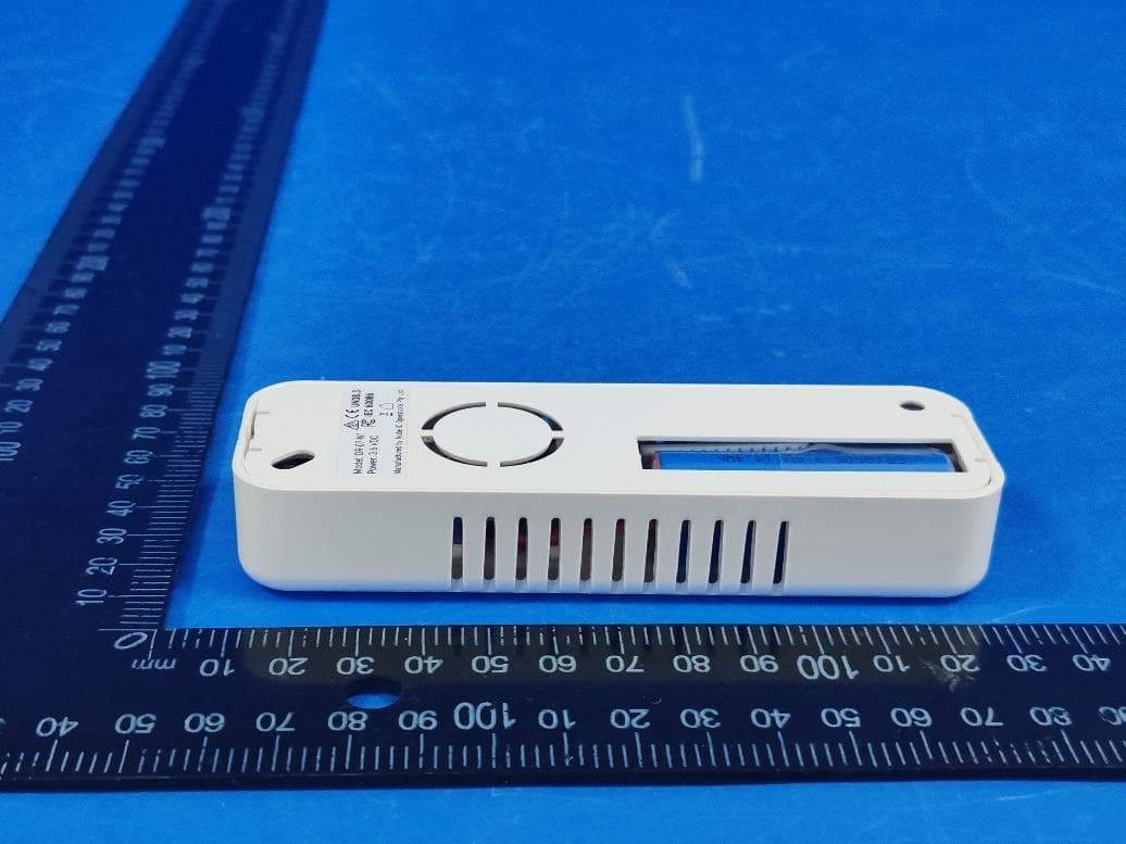
2BVYH-DR07N1
Sep 11, 2026Droplet Gen2
Equipment Class
DXX - Part 15 Low Power Communication Device Transmitter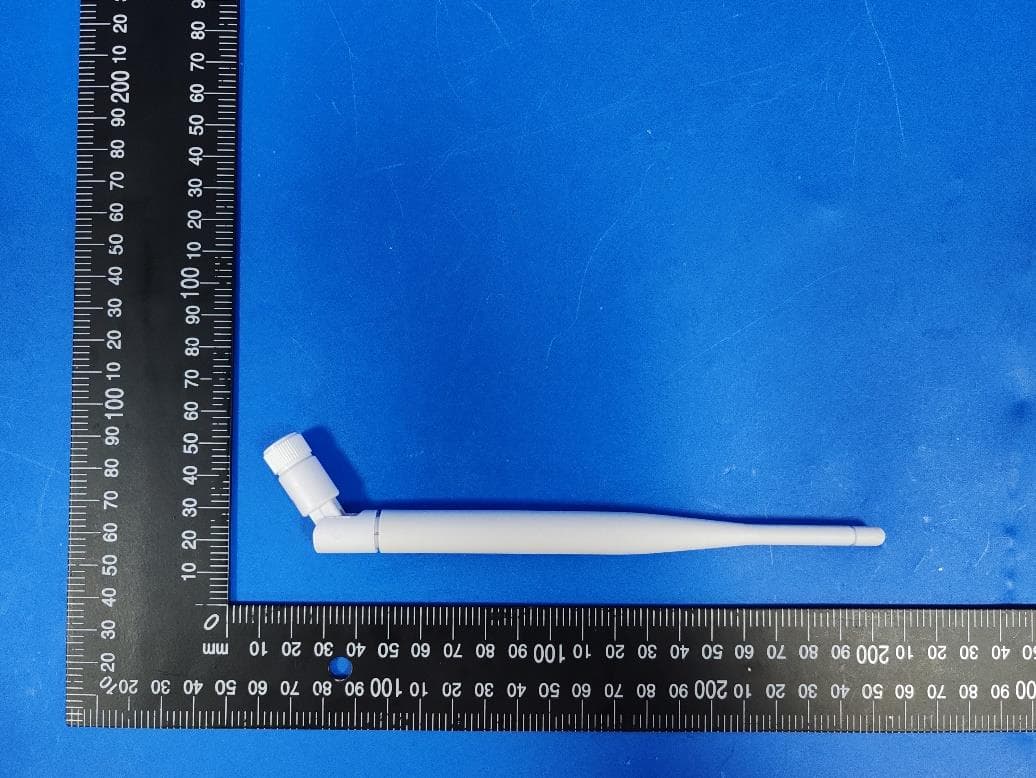
2BVYH-ZC01N1
May 20, 2026Zoneconnex
Equipment Class
DXX - Part 15 Low Power Communication Device Transmitter
2BVYH-TP01N1
May 19, 2026Touch Point LCD
Equipment Class
DTS - Digital Transmission System