A2PSKE-KOHLER7421Hospitality Remote
Shanghai KOHLER Electronics, Ltd.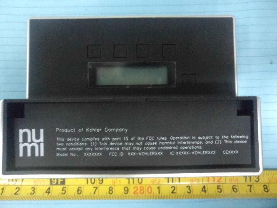
Click to zoom
Application Details
- Equipment Class
- DTS - Digital Transmission System
- Date of Grant
- Aug 13, 2012
- Application Purpose
- Original Equipment
- Date of Application
- Aug 13, 2012
- Equipment Note
- Hospitality Remote
- Frequency Range
- 2405.00000000 - 2480.00000000
- Country
- China
Documents & Files
Document Text
Text extracted from the exhibit documents filed with the FCC. Open a document above to read the original.
Users Manual
1 KOHLER® Remote Control Manual Hospitality Before using this product, please read this manual carefully and keep it. http://www.kohler.com.cn Kohler Corporation Printed in China ©Copyright Kohler China Ltd., 2012 Contents I. Overview Description of overall features ............................ x Description of button features ............................. x Description of Icons and LED lights .................... x II. Button features on top panel Flushing – Flush-eco ............................................ x Flushing – Flush-full ............................................ x Seat cover actuator – Cover close ......................... x Seat cover actuator – Cover open ......................... x Seat cover actuator – Ring open ........................... x III. Button features on front panel Stop all actuation ................................................... x Rear wash .............................................................. x Front wash.............................................................. x Dryer ...................................................................... x Music ...................................................................... x IV. Button features on back panel Description of button features on back panel.......... x Menu option – RADIO ........................................... x Menu option - HEATED FEET................................ x Menu option – HEATED SEAT .............................. x Menu option – CLEANING Setting ....................... x Menu option – SETTINGS........................................ x V. Wireless connection with the toilet Identify disconnected status...................................... x 2 Operation procedure for pairing with the toilet........ x VI. Battery Battery installation instruction .................................. x When to replace the battery ....................................... x Please read the instructions first • Before using this equipment, please read this manual and all safety precautions carefully, so as to ensure safe and proper use of the product. • The descriptions of this manual are based on the default settings of the equipment. • The contents of this manual may not only differ from the product, but may also differ from the software provided by the service provider or ISP. They are subject to change without notice. • Available features and additional services may vary due to equipment, software or ISP. • Please keep this manual properly for future reference. I. Overview Description of overall features This product is a full-featured wireless remote control of the toilet, which uses 4 alkaline batteries. The luminous icon and LED lights can display the current operating status or parameter status. Before using the remote control of the toilet, one-to-one pairing operation must be made between this product and the toilet. This product can only be used after successful pairing. The detailed description of the pairing procedure is shown in the section, “Wireless connection with the toilet”. Description of button features Buttons on top panel: ① FLUSH-ECO button ② FLUSH-FULL button ③ CLOSE button ④ COVER button ⑤ SEAT button 3 Buttons on front panel: ① STOP button ② REAR wash button ③ FRONT wash button ④ DRYER button ⑤ MUSIC button Buttons on back panel: ① MENU button ② BACK button ③ UP button ④ DOWN button ⑤ OK button 4 Description of Icons and LED lights Icons and LED lights are used to display the status of current feature or the status of parameter being adjusted. The following illustration shows all of the highlighted status: ① STOP icon is also STOP button. ② REAR wash icon is also REAR wash button. ③ FRONT wash icon is also FRONT wash button. ④ DRYER icon is also DRYER button. ⑤ MUSIC icon is also MUSIC button. ⑥ OSCILLATE icon is also OSCILLATE button. ⑦ PULSATE icon is also PULSATE button. ⑧ POSITION regulation icon contains plus and minus buttons. ⑨ PRESSURE regulation icon contains plus and minus buttons. ⑩ TEMPERATURE regulation icon contains plus and minus buttons. ⑪ VOLUME regulation icon contains plus and minus buttons. II. Button features on top panel Flushing – Flush-eco Press button, the system will activate flush-eco feature. Flushing – Flush-full Press button, the system will activate flush-full feature. Seat cover actuator – Cover close 5 Press button, the system will activate cover close feature. Seat cover actuator – Cover open Press button, the system will activate cover open feature. Seat cover actuator – Ring open Press button, the system will activate ring open feature. III. Button features on front panel Stop all actuation After button is pressed, the system will stop all actuation. The STOP icon will continue to illuminate for one second and the status of display will show as below: Rear wash After button is pressed, the system will activate rear wash feature. The status of display will show as below: 6 The buttons below the horizontal line can be regulated for rear wash parameters: oscillate, pulsate, position, pressure and temperature. If no parameter is regulated within 5 seconds, the illuminated icons and LED below the horizontal line will turn into dark, while the corresponding parameter regulation button becomes void. The status of display becomes rear wash icon flashing status and the flashing will stop after 15 seconds. If you want to regulate the parameter during the rear wash icon flashing period, you can just press the rear wash button again. The icon indicates that the “Pulsate” is off and the icon indicates that the “Pulsate” is on. The icon indicates that the “Oscillate” is off and the icon indicates that the “Oscillate” is on. Press button to increase regulation parameter at the corresponding location: position, pressure or temperature. Press button to decrease regulation parameter at the corresponding location: position, pressure or temperature. Front wash After button is pressed, the system will activate front wash feature and 7 the statu…
Text truncated - open the document above for the full version.
External Photos
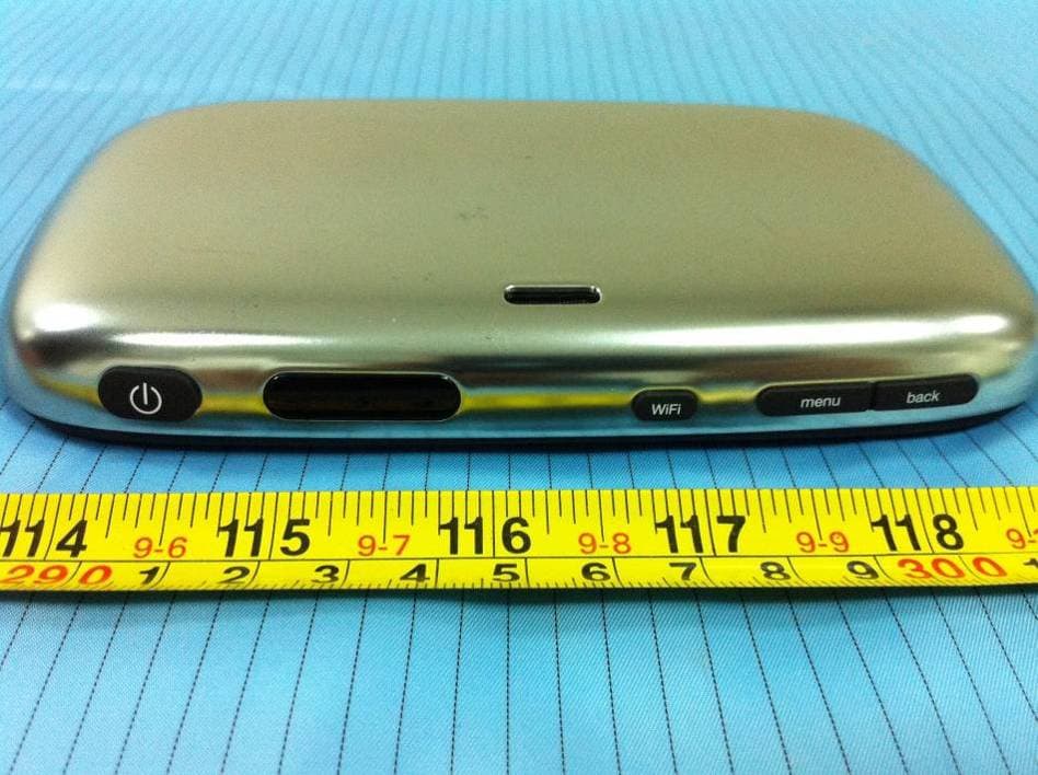
EXHIBIT B - EUT EXTERNAL PHOTOGRAPHS EUT – Front View EUT – Top View EUT – Bottom View EUT – Left View EUT – Right View
ID Label/Location Info
EXHIBIT A - FCC ID LABELING AND LOCATION FCC ID Labeling Proposed FCC ID Location The label shown shall be permanently affixed at a conspicuous location on the device and be readily visible to the user at the time purchase (Labeling requirements per 2.925) Label here
Internal Photos
EXHIBIT C - EUT INTERNAL PHOTOGRAPHS EUT – Battery off View EUT – Cover off View EUT – Main Board Top View EUT – Main Board Top without RF module View EUT – Main Board Bottom View EUT – RF Module Top View Zigbee Antenna EUT – RF Module Bottom View EUT – LCD Top View EUT – LCD Bottom View
Test Report
Note: This test report is prepared for the customer shown above and for the device described herein. It may not be duplicated or used in part without prior written consent from Bay Area Compliance Laboratories Corp. This report must not be used by the customer to claim product certification, approval, or endorsement by NVLAP*, NIST, or any agency of the Federal Government. * This report contains data that are not covered by the NVLAP accreditation and are marked with an asterisk “★” (Rev.2) FCC PART 15.247 MEASUREMENT AND TEST REPORT For Shanghai KOHLER Electronics, Ltd. Building E, 18 Jindian road, Pudong New area, Shanghai, the PRC Report Type: Original Report Product Type: Hospitality Remote Test Engineer: Mick Yin Report Number: RSZ120628001-00 Report Date: 2012-07-19 Reviewed By: Sula Huang RF Engineer Test Laboratory: Bay Area Compliance Laboratories Corp. (Shenzhen) 6/F, the 3rd Phase of WanLi Industrial Building, ShiHua Road, FuTian Free Trade Zone Shenzhen, Guangdong, China Tel: +86-755-33320018 Fax: +86-755-33320008 www.baclcorp.com.cn FCC ID: A2PSKE-KOHLER7421 Bay Area Compliance Laboratories Corp. (Shenzhen) Report No.: RSZ120628001-00 FCC Part 15.247 Page 2 of 26 TABLE OF CONTENTS GENERAL INFORMATION.......................................................................................................................................4 PRODUCT DESCRIPTION FOR EQUIPMENT UNDER TEST (EUT) .....................................................................................4 OBJECTIVE...................................................................................................................................................................4 RELATED SUBMITTAL(S)/GRANT(S).............................................................................................................................4 TEST METHODOLOGY..................................................................................................................................................4 TEST FACILITY.............................................................................................................................................................4 SYSTEM TEST CONFIGURATION ..........................................................................................................................6 DESCRIPTION OF TEST CONFIGURATION......................................................................................................................6 EUT EXERCISE SOFTWARE..........................................................................................................................................6 EQUIPMENT MODIFICATIONS.......................................................................................................................................6 BLOCK DIAGRAM OF TEST SETUP................................................................................................................................6 SUMMARY OF TEST RESULTS...............................................................................................................................7 §15.247 (i) and §1.1307 (b) (1), §2.1093 – RF EXPOSURE............................................................................................8 APPLICABLE STANDARD..............................................................................................................................................8 FCC §15.203 - ANTENNA REQUIREMENT.............................................................................................................9 APPLICABLE STANDARD..............................................................................................................................................9 ANTENNA CONNECTOR CONSTRUCTION......................................................................................................................9 FCC §15.209, §15.205 & §15.247(d) - SPURIOUS EMISSIONS.............................................................................10 APPLICABLE STANDARD............................................................................................................................................10 MEASUREMENT UNCERTAINTY..................................................................................................................................10 EUT SETUP................................................................................................................................................................10 EMI TEST RECEIVER & SPECTRUM ANALYZER SETUP..............................................................................................11 TEST EQUIPMENT LIST AND DETAILS.........................................................................................................................11 TEST PROCEDURE......................................................................................................................................................11 CORRECTED AMPLITUDE & MARGIN CALCULATION.................................................................................................11 TEST RESULTS SUMMARY..........................................................................................................................................12 TEST DATA................................................................................................................................................................12 FCC §15.247(a) (2) – 6 dB BANDWIDTH TESTING ..............................................................................................16 APPLICABLE STANDARD............................................................................................................................................16 TEST EQUIPMENT LIST AND DETAILS.........................................................................................................................16 TEST PROCEDURE...............................................................................................…
Text truncated - open the document above for the full version.
Test Setup Photos
EXHIBIT D - TEST SETUP PHOTOGRAPHS Below 1GHz: Radiated Emissions View Above 1GHz: Radiated Emissions View
Contact Information
Applicant
Yun Zhi Lin(Manager)
Test Firm
Bay Area Compliance Laboratory Corp. (Shenzhen)John Chan
Technical Specifications
| # | Rule Parts | Frequency Range | Power Output |
|---|---|---|---|
| 1 | 15C | 2.40 GHz - 2.48 GHz | 7.35 mW |
Other Applications from Shanghai KOHLER Electronics, Ltd.
A2PSKE-KOHLER3673
Dec 28, 2011Entertainment Remote Controller
Equipment Class
JBP - Part 15 Class B Computing Device Peripheral