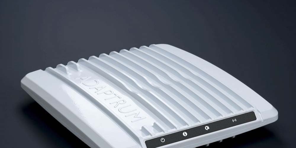
A2UACRS10TV Band Device
Adaptrum, Inc
Click to zoom
Application Details
- Equipment Class
- WGF - White Space Device with Geo-location- Fixed
- Date of Grant
- Apr 18, 2012
- Application Purpose
- Original Equipment
- Date of Application
- Nov 22, 2011
- Equipment Note
- TV Band Device
- Frequency Range
- 473.00000000 - 695.00000000
- Company
- Adaptrum, Inc
- Country
- United States
Documents & Files
Document Text
Text extracted from the exhibit documents filed with the FCC. Open a document above to read the original.
Users Manual
1 ACRS 1.0 User Manual 2 FCC Regulatory Information This device complies with part 15 of the FCC Rules. Operation is subject to the following two conditions: (1) This device may not cause harmful interference, and (2) this device must accept any interference received, including interference that may cause undesired operation. Any changes or modifications not expressly approved by the party responsible for compliance could void the user’s authority to operate the equipment. Part 15 TV Band Device Notice This equipment has been tested and found to comply with the rules for TV bands devices, pursuant to part 15 of the FCC rules. These rules are designed to provide reasonable protection against harmful interference. This equipment generates, uses and can radiate radio frequency energy and, if not installed and used in accordance with the instructions, may cause harmful interference to radio communications. If this equipment does cause harmful interference to radio or television reception, which can be determined by turning the equipment off and on, the user is encouraged to try to correct the interference by one or more of the following measures: (1) Reorient or relocate the receiving antenna. (2) Increase the separation between the equipment and receiver. (3) Connect the equipment into an outlet on a circuit different from that to which the receiver is connected. (4) Consult the manufacturer, dealer or an experienced radio/TV technician for help. Caution: Exposure to Radio Frequency Radiation. To comply with FCC RF exposure compliance requirements, for fixed configurations, a separation distance of at least 40 cm must be maintained between the antenna of this device and all persons. This device must not be co-located or operating in conjunction with any other antenna or transmitter. 3 Introduction ACRS 1.0 is the first generation Adaptrum cognitive radio system covering spectrum bands from 400 MHz to 1 GHz. Although capable to operate in other spectrum bands below 1 GHz, Adaptrum ACRS 1.0 is specifically designed to operate in the UHF TV Band (470 MHz – 698 MHz), as TV Band Devices compliant to the rules specified in CFR 47 Part 15 Subpart H. To be rules-compliant, ACRS 1.0 systems must operate as Fixed TV Band Devices and must be professionally installed. ACRS 1.0 system specifications are shown in the following table. General Specifications Technology TDD OFDMA Network topology Point to Multi-Point Frequency range 400 MHz – 1000 MHz Channel bandwidth Flexible up to 10 MHz Supporting 6, 7, 8 MHz TV channels Aggregated data rate 1 Mbps – 13 Mbps (per 6 MHz channel) Uplink/downlink Ratio Any MIMO Up to 4 antennas Transmit power < 1 W conducted Channel bandwidth efficiency ~92 percent Adjacent channel emission < -57 dBc Typical receiver sensitivity (6 MHz Channel) Signal level SNR Data Throughput -98 dBm 3.5 dB 2.7 Mbps (QPSK 1/2) -90 dBm 11.5 dB 7.1 Mbps (16 QAM 2/3) -81 dBm 20.5 dB 12 Mbps (64 QAM 3/4) Interface Specifications Antenna connector Type N female Data/control interface 10/100 Ethernet Electrical and Mechanical Specifications Power supply 110 V AC or 220 V AC Physical dimensions 17 inches x 12 inches x 4.5 inches Weight 14 LB Adaptrum ACRS 1.0 system specifications. ACRS 1.0 radio unit is enclosed in a 2U size box whose front panel and back panel are shown in the following pictures. Both the base station and the client station use the same radio unit. 4 5 ACRS 1.0 system must be professionally installed. Please refer to “ACRS 1.0 Professional Installer Manual” for detailed discussion on hardware installation. After installation, the base station and client station system configurations are illustrated in the following figures. ACRS 1.0 Base Radio Feed Cable Antenna Base Control PC Ethernet Internet Ethernet Base station installation diagram. ACRS 1.0 Client Radio Feed Cable Antenna Client Control PC Ethernet Broadband Router Ethernet Ethernet/WiFi Client Devices Client station installation diagram. A whitespace communication link is established between the base station and client station allowing the client side networking devices to connect to the Internet. Multiple client units may connect to the same base station. From the IP networking perspective, the base station acts like a layer 2 bridge to the client-side networking devices connected to the client control PC. As shown in Figure 3, both the base control PC and the client side broadband router will have IP addresses on the hosting subnet. Multiple client side devices may be visible on the subnet if the broadband router is replaced with a switch. Subnet 192.168.0.1 Base PC Broadband Router 192.168.0.100192.168.0.101 Illustration of network topology. System Operation Please refer to “ACRS 1.0 Professional Installer Manual” for detailed discussion on hardware and software installation. Once installed, the main software can be launched on the control PCs through the 6 shortcut in the “Start Menu” folder. The software will be launched in the “User” mode. When running in the “User” mode, the software only has access to limited database functions. GUI Control Interface Base station GUI control panel "Link" pane in the “User” mode. The GUI control panel is shown in the above figure. The GUI panel has a main frame body and 6 panes: Log, Link, System Information, Diagnostics, Database and Installation. Among them, the “Link” and “Database” panes are most useful in terms of monitoring system performance and interacting with TVWS database. The figure above and figure below show the base station “Link” and “Database” panes respectively. Referring to the “Database” pane below, in the “User” mode, the information entries for device registration and channel list request are disabled. These information are entered during installation and loaded directly from the system registry in the “User” mode. Note further that the channel list request is sent periodically with the period specified in the field “Update Interval” which is 300 seconds by…
Text truncated - open the document above for the full version.
Users Manual
1 ACRS 1.0 Professional Installer Manual 2 FCC Regulatory Information This device complies with part 15 of the FCC Rules. Operation is subject to the following two conditions: (1) This device may not cause harmful interference, and (2) this device must accept any interference received, including interference that may cause undesired operation. Any changes or modifications not expressly approved by the party responsible for compliance could void the user’s authority to operate the equipment. Part 15 TV Band Device Notice This equipment has been tested and found to comply with the rules for TV bands devices, pursuant to part 15 of the FCC rules. These rules are designed to provide reasonable protection against harmful interference. This equipment generates, uses and can radiate radio frequency energy and, if not installed and used in accordance with the instructions, may cause harmful interference to radio communications. If this equipment does cause harmful interference to radio or television reception, which can be determined by turning the equipment off and on, the user is encouraged to try to correct the interference by one or more of the following measures: (1) Reorient or relocate the receiving antenna. (2) Increase the separation between the equipment and receiver. (3) Connect the equipment into an outlet on a circuit different from that to which the receiver is connected. (4) Consult the manufacturer, dealer or an experienced radio/TV technician for help. Caution: Exposure to Radio Frequency Radiation. To comply with FCC RF exposure compliance requirements, for fixed configurations, a separation distance of at least 40 cm must be maintained between the antenna of this device and all persons. This device must not be co-located or operating in conjunction with any other antenna or transmitter. 3 Installation Package Content Base Station Kit The base station installation kit includes the following components: • ACRS 1.0 radio and power cord • Kathrein CL-1469B UHF-TV log-periodic antenna and cable • Base station control PC • Ethernet cables • USB memory stick with software installation package Client Station Kit The client station installation kit includes the following components: • ACRS 1.0 radio and power cord • Kathrein CL-1469B UHF-TV log-periodic antenna and cable • Client station control PC • Ethernet cables • Broadband router • USB memory stick with software installation package 4 Hardware Installation ACRS 1.0 is the first generation Adaptrum cognitive radio system covering spectrum bands from 400 MHz to 1 GHz. ACRS 1.0 is specifically designed to operate in the UHF TV Band (470 MHz – 698 MHz), as TV Band Devices compliant to the rules specified in CFR 47 Part 15 Subpart H. To be rules compliant, ACRS 1.0 systems must operate as Fixed TV Band Devices and must be professionally installed. ACRS 1.0 radio unit is enclosed in a 2U size box whose front panel and back panel are shown in the following pictures. Both the base station and the client station use the same radio unit. 5 ACRS 1.0 system has been authorized for use with the supplied Kathrein CL-1469B UHF-TV log- period antenna. Only log-periodic antennas with a gain of 10.15 dBi or less can be used with the ACRS 1.0 system and no other types of antennas should be used. The log-periodic antenna used with the ACRS 1.0 system must have well characterized gain. Antenna feed cable loss should also be characterized. The datasheet of Kathrein CL-1469B UHF-TV log-periodic antenna can be found at http://www.kathrein-scala.com/catalog/CL-1469B.pdf. The installer must ensure that the antenna assembly meets the following requirement: Antenna EIRP – Feed Cable Loss – Attenuator Setting = 7 dBi Here the “Attenuator Setting” is a software programmable output attenuation setting for the radio device that can be programmed at installation time (referring to Section “Post-Installation Setup” for discussion on how to program the setting). As an example, when a 10 dBi EIRP antenna and a feed cable with 1 dB loss are used, the “Attenuator Setting” must be programmed to: Attenuator Setting = 10 dBi – 1 dB – 7 dBi = 2 dB The “Attenuator Setting” programming must be done correctly during installation to ensure the device is compliant with the CFR 47 Part 15 Subpart H rules. 6 ACRS 1.0 Base Radio Feed Cable Antenna Base Control PC Ethernet Internet Ethernet Base station installation diagram. ACRS 1.0 Client Radio Feed Cable Antenna Client Control PC Ethernet Broadband Router Ethernet Ethernet/WiFi Client Devices Client station installation diagram. The above figures show the hardware installations at both the base station side and the client station side to allow the client side networking devices to connect to the Internet through the TV whitespace link between the base station and the client station. For both the base station and the client station installations, the ACRS 1.0 radio N-type connector is connected to the feed cable which is connected to the antenna. The Ethernet ports of the base and client radios are connected to Ethernet ports on the base control PC and client control PC. Both the base control PC and the client control PC have dual Ethernet ports. One of the Ethernet port is connected to the radio. The second Ethernet port on the base control PC is connected to a router or switch that connects to the Internet. The second Ethernet port on the client control PC is connected to a broadband router or switch which connects to the client side networking devices. Once the hardware installation is complete, follow the instructions in the following sections to perform the software installation on the control PC. Note if an installed radio unit and control PC are redeployed at a differently location, the installer must uninstall the old software and reinstall the software on the control PC. 7 Software Installation The USB memory stick comes with the package contains the software installer “AdaptrumTVBDStationInstallerSetup.exe” for the bas…
Text truncated - open the document above for the full version.
Cover Letter(s)
ADAPTRUM Adaptrum, Inc. 25 E. Trimble Road San Jose, CA 95131 Phone: 408-850-0545 Email: [email protected] April 12, 2012 Federal Communications Commission Equipment Authorization Branch 7435 Oakland Mills Rd. Columbia, MD 21046 Ref: Applicant: Adaptrum, Inc. FCC ID: A2UACRS10 Correspondence Reference Number: 41455 731 Confirmation Number: EA321847 Attention: Mark Neumann Dear Mark: Modifications were made to the Adaptrum ACRS 1.0 radio (FCC ID: A2UACRS10) during the UL CCS certification testing to meet FCC Part 15 Subpart H rules including: 1) A K&L Microwave notch filter model 5N40-611/E16.2-0/0 was added to RF output. 2) Ferrite beads were added to the radio power cord. Adaptrum will incorporate these modifications into the final ACRS 1.0 radio. Specifically, the notch filter will be installed on the RF output connector inside radio enclosure. The ferrite beads will be attached to the power cord and shipped with each radio unit. Sincerely, /S/ Stuart Rumley VP of Engineering Adaptrum, Inc.
ID Label/Location Info
PROPOSED FCC ID LABEL AND LOCATION Bottom of EUT FCC /IC Label Location ADAPTRUM INC. This device complies with Part 15 of the FCC Rules. Operation is subject to the following two conditions: (1) this device may not cause harmful interference, and (2) this device must accept any interference received, including interference that may cause undesired operation. FCC ID: A2UACRS10 Model: ACRS1.0
Parts List/Tune Up Info
Kathrein Inc., Scala Division Post Office Box 4580 Medford, OR 97501 (USA) Phone: (541) 779-6500 Fax: (541) 779-6575 Email: [email protected] Internet: www.kathrein-scala.com CL-1469B UHF-TV LOG-PERIODIC ANTENNA 8 dBd gain 470–862 MHz (Channels 14–69*) The Kathrein Scala Division CL-1469B is a ruggedly built, linearly polarized log-periodic antenna designed for professional UHF- TV transmit and receive applications. Like all Kathrein Scala Division antennas, the CL-1469B is made of the finest materials using state of the art electrical and mechanical designs resulting in superior performance and long service life. The rugged fiberglass radome protects the antenna from icing and assures stable pattern and gain performance under adverse environmental conditions. The CL-1469B may be used stand alone or in arrays for higher gain, increased side-lobe suppression, or custom azimuth patterns. *The CL-1469B covers all 6, 7, and 8 MHz UHF-TV channels worldwide (bands IV/V). (Shown horizontally polarized) Specifications: Frequency range470–862 MHz (broadband)* Gain8 dBd Power gain6.31 Impedance50 or 75 ohms VSWR< 1.5:1 PolarizationHorizontal or vertical Front-to-back ratio>35 dB Maximum input power100 watts, type "N" 75 ohm connector 250 watts, type "N" 50 ohm connector Azimuth pattern52 degrees (half-power) Elevation pattern72 degrees (half-power) ConnectorN female (50 or 75 ohms) Weight22 lb (10 kg) Dimensions29 x 17 x 12 inches (737 x 432 x 305 mm) Equivalent flat plate area2.78 ft 2 (.258 m 2 ) Wind survival rating*100 mph (160 kph) Shipping dimensions31 x 20 x 14.5 inches (787 x 508 x 368 mm) Shipping weight28.0 lb (12.7 kg) MountingMounting kits available for masts of 2.375 to 4.5 inch (60 to 114 mm) OD. See reverse for order information. 10276-C Azimuth pattern (E-plane) Elevation pattern (H-plane) * Mechanical design is based on environmental conditions as stipulated in EIA-222-F (June 1996) and/or ETS 300 019-1-4 which include the static mechanical load imposed on an antenna by wind at maximum velocity. See the Engineering Section of the catalog for further details. All specifications are subject to change without notice Kathrein Inc., Scala Division Post Office Box 4580 Medford, OR 97501 (USA) Phone: (541) 779-6500 Fax: (541) 779-6575 Email: [email protected] Internet: www.kathrein-scala.com CL-1469B UHF-TV LOG-PERIODIC ANTENNA 8 dBd gain 470–862 MHz (Channels 14–69*) Order Information: ModelDescription CL-1469B/50Antenna with 50 Ω N connector CL-1469B/75Antenna with 75 Ω N connector Note:Requires mounting kit at additional cost (see listing above). (Shown horizontally polarized) MKPS-1 Mounting Kit Mounting Options: ModelDescription MKPS-1 (shown)Mounting Kit for 2.375 inch (60 mm) OD mast. MKPS-2Mounting Kit for 2.875 inch (73 mm) OD mast. MKPS-3Mounting Kit for 3.5 inch (89 mm) OD mast. MKPS-4Mounting Kit for 4 inch (102 mm) OD mast. MKPS-5Mounting Kit for 4.5 inch (114 mm) OD mast. 29 inches (737 mm) 12 inches (305 mm) 17 inches (432 mm)
RF Exposure Info
REPORT EUT: TV B COMPLIA 47173 BE This r 9. MAX FCC RUL §1.1310 human e of portab chapter. NO: 11U1370 BAND DEVIC ANCE CERTIF ENICIA STREE report shall n XIMUM P LES The criteria xposure to r ble devices w 01-3 CE FICATION SE ET, FREMON not be repro ERMISSI listed in Tab radio-freque which shall b Pa ERVICES (UL NT, CA 94538 oduced excep BLE EXP ble 1 shall be ncy (RF) rad be evaluated age 79 of 85 CCS) , US A TE pt in full, wit POSURE e used to ev diation as sp d according t EL: (510) 771- thout the wri valuate the e pecified in §1 to the provis DATE: NO FCC FORM -1000 FA itten approva environmenta 1.1307(b), e sions of §2.1 OVEMBER 22, C ID: A2UAC NO: CCSUP4 AX: (510) 661 al of UL CCS al impact of xcept in the 093 of this , 2011 CRS10 4701D -0888 S. case REPORT NO: 11U13701-3 DATE: NOVEMBER 22, 2011 EUT: TV BAND DEVICE FCC ID: A2UACRS10 Page 80 of 85 COMPLIANCE CERTIFICATION SERVICES (UL CCS) FORM NO: CCSUP4701D 47173 BENICIA STREET, FREMONT, CA 94538, USA TEL: (510) 771-1000 FAX: (510) 661-0888 This report shall not be reproduced except in full, without the written approval of UL CCS. EQUATIONS Power density is given by: S = EIRP / (4 * Pi * D^2) where S = Power density in mW/cm^2 EIRP = Equivalent Isotropic Radiated Power in mW D = Separation distance in cm Distance is given by: D = SQRT (EIRP / (4 * Pi * S)) where D = Separation distance in cm EIRP = Equivalent Isotropic Radiated Power in mW S = Power density in mW/cm^2 In the table(s) below, Power and Gain are entered in units of dBm and dBi respectively and conversions to linear forms are used for the calculations. LIMITS From FCC §1.1310 Table 1 (B), the maximum value of S = f/1500 mW/cm^2, where f is the operating frequency in MHz. MEASUREMENT NOTES The conducted output power was measured with the device operating at the only source-based TDD duty cycle, therefore no duty cycle correction is applied to the RF Exposure calculations. REPORT NO: 11U13701-3 DATE: NOVEMBER 22, 2011 EUT: TV BAND DEVICE FCC ID: A2UACRS10 Page 81 of 85 COMPLIANCE CERTIFICATION SERVICES (UL CCS) FORM NO: CCSUP4701D 47173 BENICIA STREET, FREMONT, CA 94538, USA TEL: (510) 771-1000 FAX: (510) 661-0888 This report shall not be reproduced except in full, without the written approval of UL CCS. RESULTS FOR FIXED OPERATION In accordance with §15.709 (d), the minimum separation distance for a Fixed TVBD is 40 cm. RF Exposure for Maximum Output Power, antenna gain <= 8 dBi FrequencyModeSeparationOutputAntennaPowerFCC DistancePowerGainDensityLimit ( MHz )( cm)( dBm)( dBi)( mW / cm^2)( mW /cm^2) 473.0QPSK4026.408.000.140.315 581.0QPSK4027.108.000.160.387 695.0QPSK4027.008.000.160.463 473.016QAM4026.408.000.140.315 581.016QAM4027.008.000.160.387 695.016QAM4027.008.000.160.463 473.064QAM4026.808.000.150.315 581.064QAM4027.708.000.180.387 695.064QAM4027.308.000.170.463 REPORT NO: 11U13701-3 DATE: NOVEMBER 22, 2011 EUT: TV BAND DEVICE FCC ID: A2UACRS10 Page 82 of 85 COMPLIANCE CERTIFICATION SERVICES (UL CCS) FORM NO: CCSUP4701D 47173 BENICIA STREET, FREMONT, CA 94538, USA TEL: (510) 771-1000 FAX: (510) 661-0888 This report shall not be reproduced except in full, without the written approval of UL CCS. RESULTS FOR PERSONAL OPERATION The source-based time-averaged output for configuration as a Personal TVBD can be greater than 20 mW therefore the device is subject to routine RF exposure evaluation. RF Exposure for Reduced Output Power, antenna gain <= 6 dBi (Conducted output power is reduced to meet the Personal Device PSD and EIRP limits) RF Exposure for Reduced Output Power, antenna gain <= 2 dBi (Conducted output power is reduced to meet the Personal Device PSD and EIRP limits) FrequencyModeSeparationOutputAntennaPowerFCC DistancePowerGainDensityLimit ( MHz )( cm)( dBm)( dBi)( mW /cm^2)( mW /cm^2) 473.0QPSK2016.402.000.010.315 581.0QPSK2017.102.000.020.387 695.0QPSK2017.002.000.020.463 473.016QAM2016.402.000.010.315 581.016QAM2017.002.000.020.387 695.016QAM2017.002.000.020.463 473.064QAM2016.802.000.020.315 581.064QAM2017.702.000.020.387 695.064QAM2017.302.000.020.463 FrequencyModeSeparationOutputAntennaPowerFCC DistancePowerGainDensityLimit ( MHz )( cm)( dBm)( dBi)( mW /cm^2)( mW / cm^2) 473.0QPSK2014.006.000.020.315 581.0QPSK2014.006.000.020.387 695.0QPSK2014.006.000.020.463 473.016QAM2014.006.000.020.315 581.016QAM2014.006.000.020.387 695.016QAM2014.006.000.020.463 473.064QAM2014.006.000.020.315 581.064QAM2014.006.000.020.387 695.064QAM2014.006.000.020.463
Test Setup Photos
REPORT EUT: TV B COMPLIA 47173 BE This r 10. S ANTENNA NO: 11U137 0 BAND DEVIC ANCE CERTIF ENICIA STREE report shall n SETUP PH A PORT CON ANTENN 01-3B CE FICATION SE ET, FREMON not be repro HOTOS NDUCTED M NA PORT SE Pa ERVICES (UL NT, CA 94538 oduced excep EASUREME ETUP age 83 of 85 CCS) , US A TE pt in full, wit NT SETUP EL: (510) 771- thout the wri DAT FC C FORM -1000 FA itten approva E: APRIL 13, C ID: A2UAC NO: CCSUP4 AX: (510) 661 al of UL CCS , 2012 CRS10 4701D -0888 S. REPORT EUT: TV B COMPLIA 47173 BE This r RADIATE NO: 11U1370 BAND DEVIC ANCE CERTIF ENICIA STREE report shall n ED EMISSION RADIATE RADAIAT 01-3B CE FICATION SE ET, FREMON not be repro NS SETUP ED FRONT TED BACK Pa ERVICES (UL NT, CA 94538 oduced excep PHOTO PHOTO age 84 of 85 CCS) , US A TE pt in full, wit EL: (510) 771- thout the wri DAT FC C FORM -1000 FA itten approva E: APRIL 13, C ID: A2UAC NO: CCSUP4 AX: (510) 661 al of UL CCS , 2012 CRS10 4701D -0888 S. REPORT EUT: TV B COMPLIA 47173 BE This r POWERL NO: 11U1370 BAND DEVIC ANCE CERTIF ENICIA STREE report shall n LINE CONDU LINE CO LINE CO 01-3B CE FICATION SE ET, FREMON not be repro CTED EMISS ONDUCTED ONDUCTED Pa ERVICES (UL NT, CA 94538 oduced excep SIONS MEAS END O FRONT PH BACK PHO age 85 of 85 CCS) , US A TE pt in full, wit SUREMENT S OF REPO OTO OTO EL: (510) 771- thout the wri SETUP ORT DAT FC C FORM -1000 FA itten approva E: APRIL 13, C ID: A2UAC NO: CCSUP4 AX: (510) 661 al of UL CCS , 2012 CRS10 4701D -0888 S.
Contact Information
Applicant
Haiyun Tang(CEO)
Technical Contact
Compliance Certification Services(UL CCS)Claire Hoque
[email protected](510) 771-1000
47173 Benicia Street · Fremont, California · United States
Test Firm
Compliance Certification ServicesThu Chan
Technical Specifications
| # | Rule Parts | Frequency Range | Power Output |
|---|---|---|---|
| 1 | 15H | 473 MHz - 695 MHz | 617.00 mW |
Other Applications from Adaptrum, Inc
A2UACRS20F
May 01, 2014Fixed TV Band Device
Equipment Class
WGF - White Space Device with Geo-location- Fixed