A2UACRS20FFixed TV Band Device
Adaptrum, Inc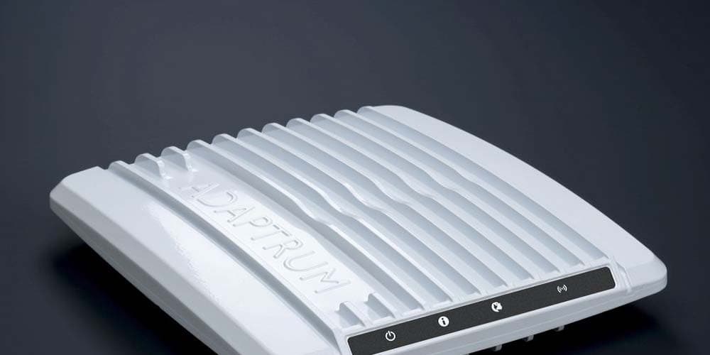
Click to zoom
Application Details
- Equipment Class
- WGF - White Space Device with Geo-location- Fixed
- Date of Grant
- May 01, 2014
- Application Purpose
- Original Equipment
- Date of Application
- Nov 04, 2013
- Equipment Note
- Fixed TV Band Device
- Frequency Range
- 473.00000000 - 695.00000000
- Company
- Adaptrum, Inc
- Country
- United States
Documents & Files
Document Text
Text extracted from the exhibit documents filed with the FCC. Open a document above to read the original.
Users Manual
1 ACRS 2.0 Professional Installer Manual 2 FCC Regulatory Information This device complies with part 15 of the FCC Rules. Operation is subject to the following two conditions: (1) This device may not cause harmful interference, and (2) this device must accept any interference received, including interference that may cause undesired operation. Any changes or modifications not expressly approved by the party responsible for compliance could void the user’s authority to operate the equipment. Part 15 TV Band Device Notice This equipment has been tested and found to comply with the rules for TV bands devices, pursuant to part 15 of the FCC rules. These rules are designed to provide reasonable protection against harmful interference. This equipment generates, uses and can radiate radio frequency energy and, if not installed and used in accordance with the instructions, may cause harmful interference to radio communications. If this equipment does cause harmful interference to radio or television reception, which can be determined by turning the equipment off and on, the user is encouraged to try to correct the interference by one or more of the following measures: (1) Reorient or relocate the receiving antenna. (2) Increase the separation between the equipment and receiver. (3) Connect the equipment into an outlet on a circuit different from that to which the receiver is connected. (4) Consult the manufacturer, dealer or an experienced radio/TV technician for help. Caution: Exposure to Radio Frequency Radiation. To comply with FCC RF exposure compliance requirements, for fixed configurations, a separation distance of at least 40 cm must be maintained between the antenna of this device and all persons. This device must not be co-located or operating in conjunction with any other antenna or transmitter. 3 Installation Package Content Base Station Kit The base station installation kit includes the following components: • ACRS 2.0 radio and power cord • Antenna and cable • Ethernet cables • USB memory stick with software installation package Client Station Kit The client station installation kit includes the following components: • ACRS 2.0 radio and power cord • Antenna and cable • Ethernet cables • Broadband router • USB memory stick with software installation package 4 Hardware Installation ACRS 2.0 is the second generation Adaptrum cognitive radio system covering spectrum bands from 400 MHz to 1 GHz. ACRS 2.0 is specifically designed to operate in the UHF TV Band (470 MHz – 698 MHz), as TV Band Devices compliant to the rules specified in CFR 47 Part 15 Subpart H. To be rules compliant, ACRS 2.0 systems must operate as Fixed TV Band Devices and must be professionally installed. ACRS 2.0 radio has a fully enclosed weather-proof aluminum construction as shown in the following pictures. There are status 4 LEDs on the front and an SMA antenna port and an Ethernet port on the back. The unit is powered through Ethernet and there is no separate power connector. The last picture below shows an example pole-mount installation. Both the base and the client stations use the same radio unit. 5 6 ACRS 2.0 system has been authorized for use with the following antenna types: 1) Log-periodic antennas with a gain of 10.15 dBi or less. 2) Bowtie antenna with backplane reflector with a gain of 11.8 dBi or less. 3) Print-circuit-board (PCB) omni-directional bowtie antenna with a gain of 2.3 dBi or less. The antenna used with the ACRS 2.0 system must have well characterized gain. Antenna feed cable loss should also be characterized. Please consult with Adaptrum if you have questions about what types of antennas can be used with ACRS 2.0 radio system. 7 The following figures show the hardware installations at both the base station side and the client station side to allow the client side networking devices to connect to the Internet through the TV whitespace link between the base station and the client station. ACRS 2.0 Base Radio Feed Cable Antenna Ethernet Switch Ethernet Internet Ethernet Base Control PC Base station installation diagram. ACRS 2.0 Client Radio Feed Cable Antenna Ethernet Switch Ethernet Broadband Router Ethernet Ethernet/WiFi Client Devices Client Control PC Client station installation diagram. For both the base station and the client station installations, the ACRS 2.0 radio SMA connector is connected to the feed cable which is connected to the antenna. The base and client radio operation can be controlled through base control PC or client control PC connected to the radios through Ethernet switches. Once the hardware installation is complete, follow the instructions in the following sections to perform the software installation on the control PC. Note if an installed radio unit is redeployed at a differently location, the installer must reconfigure the radio coordinates to reflect the location change. 8 Software Installation The USB memory stick comes with the package contains the software installer “AdaptrumTVBDStationInstallerSetup.exe” for the base station software installation or “AdaptrumTVBDClientInstallerSetup.exe” for the client station software installation. The software can run on Windows XP or Windows 7. The following describes the installation process on a Windows 7 PC. 1) On the base control PC, double click the installer executable. The following set up program will show up. Select “Next” to continue installation. 2) Select the desired installation directory and click “Next”. The default is “C:\Program Files\Adaptrum” 3) Select a folder in the Start Menu to place the program executable shortcut and click “Next”. The default is “AdaptrumStation” for the base station installation. 9 4) Double check the folder selections and click “Install” to install the program. 5) The installation progress window will show. 10 6) Once the installation is complete, click “Finish”. The software installation on the client station follows the same steps except the default “Start Menu” folder for the…
Text truncated - open the document above for the full version.
Users Manual
1 ACRS 2.0 User Manual 2 FCC Regulatory Information This device complies with part 15 of the FCC Rules. Operation is subject to the following two conditions: (1) This device may not cause harmful interference, and (2) this device must accept any interference received, including interference that may cause undesired operation. Any changes or modifications not expressly approved by the party responsible for compliance could void the user’s authority to operate the equipment. Part 15 TV Band Device Notice This equipment has been tested and found to comply with the rules for TV bands devices, pursuant to part 15 of the FCC rules. These rules are designed to provide reasonable protection against harmful interference. This equipment generates, uses and can radiate radio frequency energy and, if not installed and used in accordance with the instructions, may cause harmful interference to radio communications. If this equipment does cause harmful interference to radio or television reception, which can be determined by turning the equipment off and on, the user is encouraged to try to correct the interference by one or more of the following measures: (1) Reorient or relocate the receiving antenna. (2) Increase the separation between the equipment and receiver. (3) Connect the equipment into an outlet on a circuit different from that to which the receiver is connected. (4) Consult the manufacturer, dealer or an experienced radio/TV technician for help. Caution: Exposure to Radio Frequency Radiation. To comply with FCC RF exposure compliance requirements, for fixed configurations, a separation distance of at least 40 cm must be maintained between the antenna of this device and all persons. This device must not be co-located or operating in conjunction with any other antenna or transmitter. 3 Introduction ACRS 2.0 is the second generation Adaptrum cognitive radio system covering spectrum bands from 400 MHz to 1 GHz. Although capable to operate in other spectrum bands below 1 GHz, Adaptrum ACRS 2.0 is specifically designed to operate in the UHF TV Band (470 MHz – 698 MHz), as TV Band Devices compliant to the rules specified in CFR 47 Part 15 Subpart H. To be rules-compliant, ACRS 2.0 systems must operate as Fixed TV Band Devices and must be professionally installed. ACRS 2.0 system specifications are shown in the following table. General Specifications Regulatory Compliance FCC Part 15 Subpart H Technology TDD OFDMA Network topology Point to Multi-Point Mobility Support Nomadic & Vehicular up to 40 m/s Frequency Range 400 MHz – 1000 MHz Channel Bandwidth Flexible up to 10 MHz Supporting 6, 7, 8 MHz TV channels Aggregated Layer 2 Data Rate (Uplink + Downlink) / 6MHz 1 Mbps – 16 Mbps Uplink/Downlink Ratio Any e.g. 1:1, 1:3, 4:1 Transmit Power 100 mW conducted Channel Bandwidth Efficiency 94 percent Adjacent Channel Emission < -55 dBc Receiver Sensivity (6 MHz Channel) Level SNR Data Throughput -98 dBm 3.5 dB 2.7 Mbps (QPSK 1/2) -90 dBm 11.5 dB 7.1 Mbps (16 QAM 2/3) -81 dBm 20.5 dB 12 Mbps (64 QAM 3/4) Interface Specifications Optional external antenna connector SMA Female Data/Control 10/100 Ethernet Electrical and Mechanical Specifications Supply 48 V PoE Physical Dimensions 8.5 inches x 7.5 inches x 1.5 inches Weight 3.6 LB Table 1: Adaptrum ACRS 2.0 system specifications. 4 ACRS 2.0 radio has a fully enclosed weather-proof aluminum construction as shown in the following pictures. There are status 4 LEDs on the front and an SMA antenna port and an Ethernet port on the back. The unit is powered through Ethernet and there is no separate power connector. The last picture below shows an example pole-mount installation. Both the base and the client stations use the same radio unit. 5 6 ACRS 2.0 system must be professionally installed. Please refer to “ACRS 2.0 Professional Installer Manual” for detailed discussion on hardware installation. After installation, the base station and client station system configurations are illustrated in the following figures. ACRS 2.0 Base Radio Feed Cable Antenna Ethernet Switch Ethernet Internet Ethernet Base Control PC Base station installation diagram. 7 ACRS 2 .0 Client Radio Feed Cable Antenna Ethernet Switch Ethernet Broadband Router Ethernet Ethernet/WiFi Client Devices Client Control PC Client station installation diagram. A whitespace communication link is established between the base station and client station allowing the client side networking devices to connect to the Internet. Multiple client units may connect to the same base station. From the IP networking perspective, the base station acts like a layer 2 bridge to the client-side networking devices connected to the client control PC. As shown in the following figure, both the base control PC and the client side broadband router will have IP addresses on the hosting subnet. Multiple client side devices may be visible on the subnet if the broadband router is replaced with a switch. Subnet 192.168.0.1 Base PC Broadband Router 192.168.0.100192.168.0.101 Illustration of network topology. System Operation Please refer to “ACRS 2.0 Professional Installer Manual” for detailed discussion on hardware and software installation. Once installed, the main software can be launched on the control PCs through the shortcut in the “Start Menu” folder. The software will be launched in the “User” mode. When running in the “User” mode, the software only has access to limited database functions. 8 GUI Control Interface Base station GUI control panel "Link" pane in the “User” mode. The GUI control panel is shown in the above figure. The GUI panel has a main frame body and 6 panes: Log, Link, System Information, Diagnostics, Database and Installation. Among them, the “Link” and “Database” panes are most useful in terms of monitoring system performance and interacting with TVWS database. The figure above and figure below show the base station “Link” and “Database” panes respectively. Referring to the “Database” pane below, in the …
Text truncated - open the document above for the full version.
Cover Letter(s)
ADAPTRUM November 4, 2013 UL Verification Services Inc. 47173 Benicia Street Fremont, CA 94538, USA To whom it may concern: Adaptrum, Inc. 25 E. Trimble Road San Jose, CA 95131 Phone: 408-<!50-0545 Email: [email protected] I, the undersigned, hereby authorize UL Verification Services Inc. to act on our behalf in all manners relating to application for equipment authorization, including signing of all documents relating to these matters. Any and all acts carried out by UL Verification Services Inc. on our behalf shall have the same effect as acts of our own. I, the undersigned, hereby certify that we are not subject to a denial of federal benefits, that includes FCC benefits, pursuant to Section 5301 of the Anti-Drug Abuse Act of 1988, 21 U.S.C. 853(a). In authorizing UL Verification Services Inc. as our representative, we still recognize that we are responsible to: a) comply with the relevant provisions of the certification program; b) make all necessary arrangements for the conduct of the evaluation, including provision for examining documentation and access to all areas, records (including internal audit reports) and personnel for the purposes of evaluation (e.g. testing, inspection, assessment, surveillance, reassessment) and resolution of complaints; c) make claims regarding certification only in respect of the scope for which certification has been granted; d) do not use our product certification in such a manner as to bring the Certification Division into disrepute and not make any statement regarding our product certification which the Certification Division may consider misleading or unauthorized; e) upon suspension or cancellation of certification, discontinue use of all advertising matter that contains any reference thereto and return any certification documents as required by the Certification Division; ADAPTRUM Adaptrum, Inc. 25 E. Trimble Road San Jose. CA 95131 Phone 408.{!50-0545 Email [email protected] f) use certification only to indicate the products are certified as being in conformity with specified standards; g) endeavor to ensure that no certificate or report nor any part thereof is used in a misleading manner; h) ensure that any reference to our product certification in communication media such as documents, brochures or advertising, complies with the requirements of the Certification Division; i) keep a record of all complaints made known to the us relating to the product's compliance with requirements of the relevant standard and to make these records available to the Certification Division when requested; j) take appropriate action with respect to such complaints and any deficiencies found in products or services that affect compliance with the requirements for certification; k) document the actions taken. This authorization is valid until further written notice from the applicant. Sincerely Yours, Haiyun Tang, CEO, Adaptrum Inc. REMARK: I. This authorization letter will be sent along with your application when filing with the Certification Division. 2. Please follow the format and type it on company letterhead and send original to us. 3. Authorized signature must be in agreement with grantee code contact in FCC database.
Cover Letter(s)
ADAPTRUM November 4, 2013 Federal Communications Commission Equipment Authorization Branch 7435 Oakland Mills Rd. Columbia, MD 21046 Subject: Request for Confidentiality FCC ID: A2UACRS20F Dear Examiner: Adaptrum, Inc. 25 E. Tnmble Road San Jose, CA 95131 Phone 408-<JS0-0545 Email: [email protected] Pursuant to the provisions of Sections 0.457 and 0.459 ofthe Commission's rules (47 CFR §§ 0.457, 0.459), we are requesting the Commission to withhold the following attachments as confidential document from public disclosure indefinitely: Schematic Diagram Block Diagram Above mentioned document contains detailed system and equipment description are considered as proprietary information in operation ofthe equipment. The public disclosure of above documents might be harmful to our company and would give competitor an unfair advantage in the market. In additional to above mentioned documents, pursuant to Public Notice DA 04-1705 of the Commission's policy, in order to comply with the marketing regulations in 47 CFR §2.803 and the importation rules in 47 CFR §2.1204, while ensuring that business sensitive information remains confidential until the actual marketing of newly authorized devices. We are requesting the commission to grant short-term confidentiality request on the following attachments until 6 months after the grant of equipment authorization is issued. Internal Photos It is our understanding that all measurement test reports, FCC TD label format and correspondent during certification review process cannot be granted as confidential ADAPTRUM Adaptrum, Inc. 25 E T nmble Road San Jose. CA 95131 Phone: 408-<lS0-0545 Email. [email protected] documents and those information will be available for public review once the grant of equipment authorization is issued. Sincerely, --~ ~-~ Haiyun Tang CEO Adaptrum, Inc.
Parts List/Tune Up Info
Kathrein Inc., Scala Division Post Office Box 4580 Medford, OR 97501 (USA) Phone: (541) 779-6500 Fax: (541) 779-6575 Email: [email protected] Internet: www.kathrein-scala.com CL-1469B UHF-TV LOG-PERIODIC ANTENNA 8 dBd gain 470–862 MHz (Channels 14–69*) The Kathrein Scala Division CL-1469B is a ruggedly built, linearly polarized log-periodic antenna designed for professional UHF- TV transmit and receive applications. Like all Kathrein Scala Division antennas, the CL-1469B is made of the finest materials using state of the art electrical and mechanical designs resulting in superior performance and long service life. The rugged fiberglass radome protects the antenna from icing and assures stable pattern and gain performance under adverse environmental conditions. The CL-1469B may be used stand alone or in arrays for higher gain, increased side-lobe suppression, or custom azimuth patterns. *The CL-1469B covers all 6, 7, and 8 MHz UHF-TV channels worldwide (bands IV/V). (Shown horizontally polarized) Specifications: Frequency range470–862 MHz (broadband)* Gain8 dBd Power gain6.31 Impedance50 or 75 ohms VSWR< 1.5:1 PolarizationHorizontal or vertical Front-to-back ratio>35 dB Maximum input power100 watts, type "N" 75 ohm connector 250 watts, type "N" 50 ohm connector Azimuth pattern52 degrees (half-power) Elevation pattern72 degrees (half-power) ConnectorN female (50 or 75 ohms) Weight22 lb (10 kg) Dimensions29 x 17 x 12 inches (737 x 432 x 305 mm) Equivalent flat plate area2.78 ft 2 (.258 m 2 ) Wind survival rating*100 mph (160 kph) Shipping dimensions31 x 20 x 14.5 inches (787 x 508 x 368 mm) Shipping weight28.0 lb (12.7 kg) MountingMounting kits available for masts of 2.375 to 4.5 inch (60 to 114 mm) OD. See reverse for order information. 10276-C Azimuth pattern (E-plane) Elevation pattern (H-plane) * Mechanical design is based on environmental conditions as stipulated in EIA-222-F (June 1996) and/or ETS 300 019-1-4 which include the static mechanical load imposed on an antenna by wind at maximum velocity. See the Engineering Section of the catalog for further details. All specifications are subject to change without notice Kathrein Inc., Scala Division Post Office Box 4580 Medford, OR 97501 (USA) Phone: (541) 779-6500 Fax: (541) 779-6575 Email: [email protected] Internet: www.kathrein-scala.com CL-1469B UHF-TV LOG-PERIODIC ANTENNA 8 dBd gain 470–862 MHz (Channels 14–69*) Order Information: ModelDescription CL-1469B/50Antenna with 50 Ω N connector CL-1469B/75Antenna with 75 Ω N connector Note:Requires mounting kit at additional cost (see listing above). (Shown horizontally polarized) MKPS-1 Mounting Kit Mounting Options: ModelDescription MKPS-1 (shown)Mounting Kit for 2.375 inch (60 mm) OD mast. MKPS-2Mounting Kit for 2.875 inch (73 mm) OD mast. MKPS-3Mounting Kit for 3.5 inch (89 mm) OD mast. MKPS-4Mounting Kit for 4 inch (102 mm) OD mast. MKPS-5Mounting Kit for 4.5 inch (114 mm) OD mast. 29 inches (737 mm) 12 inches (305 mm) 17 inches (432 mm)
Parts List/Tune Up Info
Technical Data Sheet:Antennas Direct DB2E Antenna Physical Data: Dimensions: Width = 23 in.Height = 16.25 in.Depth = 7 in. Weight:TBD Turning Radius:11.5 in. Electrical Data: Design Pass Band:UHF470 MHz to 698 MHzChannels 14 – 51 Impedance:75 ohm Connector:F-Female Performance Data: Peak Gain:11.8 dBi@ 698 MHz VSWR:3.0 Max470 MHz to 698 MHz Notes: 1.Unless stated otherwise, all performance data computed using Remcom, Inc. X-FDTD 7.0 simulator. 2.Assumptions: PEC, free space. PCB balun included. 75 ohm reference. 3.Gain is specified dBi (isotropic) per IEEE definition. Mismatch losses not included. 4.There are two common meanings for Front-to-Back Ratio (F/B). One specifies ratio as measured 180 degrees opposite boresight. The other, used by IEEE specifies the ratio of boresight gain to maximum gain in rear hemisphere. The IEEE definition is the most conservative. IEEE F/B values shown here are computed based on azimuth and elevation cuts provided in this document. Copyright (c) Antennas Direct, Inc., 2011. Page 1 of 7 Illustration 1: DB2E Frequency (MHz) 4709.0655.56813.46 5469.9250.56115.52 62210.944.75917.5 69811.7339.65418.53 Boresight Gain (dBi) Azimuth – Half Power Beam Width (deg) Elevation – Half Power Beam Width (deg) IEEE Rear Hemisphere F/B (dB) Illustration 2: DB2E - Gain versus Azimuth Angle. Copyright (c) Antennas Direct, Inc., 2011. Page 2 of 7 Illustration 3: DB2E - Gain versus Elevation Angle. Copyright (c) Antennas Direct, Inc., 2011. Page 3 of 7 Illustration 4: DB2E - Boresight Gain versus Frequency. Copyright (c) Antennas Direct, Inc., 2011. Page 4 of 7 Illustration 5: DB2E - Computed VSWR versus Frequency. PCB balun included. 75 ohm reference. Measured better, see next plot. Copyright (c) Antennas Direct, Inc., 2011. Page 5 of 7 Copyright (c) Antennas Direct, Inc., 2011. Page 6 of 7 Illustration 6: DB2E - VSWR versus Frequency measured outdoors with HP8510C VNA. Copyright (c) Antennas Direct, Inc., 2011. Page 7 of 7 Illustration 7: DB2E - Gain relative to DB2 measured outdoors with HP8510C VNA. Up to 4 dB enhancement.
Parts List/Tune Up Info
PCB Bowtie Antenna Pattern Data PCB Bowtie Frequency (MHz) Min gain (dBi) Max gain (dBi) 400 -4 -1.22 500 -1.31 1.89 600 -0.26 1.6 700 -0.99 2.32 800 -0.79 2.06 900 -2.7 1.98 -20 -18 -16 -14 -12 -10 -8 -6 -4 -2 0 2 4 1 5 9 13 17 21 25 29 33 37 41 45 49 53 57 61 65 69 73 77 81 85 89 93 97 101 105 109 113 117 121 125 129 133 137 141 145 149 153 157 161 165 169 173 177 181 185 189 193 197 201 205 209 213 217 221 225 229 233 237 241 245 249 253 257 261 265 269 273 277 281 285 289 293 297 301 305 309 313 317 321 325 329 333 337 341 345 349 353 357 PCB Bowtie Azimuth Pattern 400 MHz 500 MHz 600 MHz 700 MHz 800 MHz 900 MHz
Test Report
FCC CFR47 PART 15 SUBPART H DATABASE TEST REPORT FOR FIXED TV BAND DEVICE MODEL NUMBER: ACRS 2.0 REPORT NUMBER: 13U15452 -5 FCC ID: A2UACRS20F ISSUE DATE: JANUARY 29, 2014 Prepared for ADAPTRUM 25 E. TRIMBLE ROAD SAN JOSE, CA 95131 Prepared by UL VERIFICATION SERVICES INC. 47173 BENICIA STREET FREMONT, CA 94538, U.S.A. TEL: (510) 771-1000 FAX: (510) 661-0888 REPORT NO: 14U16838-1 DATE: JANUARY 29, 2014 EUT: FIXED TV BAND DEVICE FCC ID: A2UACRS20F Page 2 of 84 UL VERIFICATION SERVICES INC. FORM NO: CCSUP4701I 47173 BENICIA STREET, FREMONT, CA 94538, USA TEL: (510) 771-1000 FAX: (510) 661-0888 This report shall not be reproduced except in full, without the written approval of UL Verification Services Inc. Revision History Rev. Issue Date Revisions Revised By -- 01/29/2014 Initial Issue F. de Anda REPORT NO: 14U16838-1 DATE: JANUARY 29, 2014 EUT: FIXED TV BAND DEVICE FCC ID: A2UACRS20F Page 3 of 84 UL VERIFICATION SERVICES INC. FORM NO: CCSUP4701I 47173 BENICIA STREET, FREMONT, CA 94538, USA TEL: (510) 771-1000 FAX: (510) 661-0888 This report shall not be reproduced except in full, without the written approval of UL Verification Services Inc. TABLE OF CONTENTS 1. ATTESTATION OF TEST RESULTS ................................................................................. 5 2. TEST METHODOLOGY ...................................................................................................... 6 3. FACILITIES AND ACCREDITATION ................................................................................. 6 4. CALIBRATION AND UNCERTAINTY ................................................................................ 6 4.1. MEASURING INSTRUMENT CALIBRATION .............................................................. 6 4.2. SAMPLE CALCULATION ............................................................................................ 6 4.3. MEASUREMENT UNCERTAINTY ............................................................................... 6 5. EQUIPMENT UNDER TEST ............................................................................................... 7 5.1. DESCRIPTION OF EUT .............................................................................................. 7 5.2. DATABASE information ............................................................................................... 7 5.3. MAXIMUM OUTPUT POWER...................................................................................... 7 5.4. DESCRIPTION OF AVAILABLE ANTENNAS .............................................................. 7 5.5. SOFTWARE AND FIRMWARE .................................................................................... 7 5.6. DETAILS OF TESTED SYSTEM ................................................................................. 7 6. TEST AND MEASUREMENT EQUIPMENT ......................................................................10 7. DATABASE CERTIFICATION REQUIREMENTS .............................................................11 8. BASE STATION DATABASE CERTIFICATION TEST RESULTS ....................................12 8.1. §15.713(F)(3) FIXED TVBD REGISTRATION .............................................................12 8.1.1. SUCCESSFUL REGISTRATION .........................................................................13 8.1.2. FAILED REGISTRATION – RESTRICTED COORDINATES ...............................16 8.1.3. FAILED REGISTRATION – HAAT .......................................................................17 8.1.4. FAILED REGISTRATION – ANTENNA HEIGHT AGL .........................................20 8.1.5. FAILED REGISTRATION – INCOMPLETE CONTACT INFORMATION ..............21 8.2. §15.707(A) FIXED TVBD RELOCATED ......................................................................22 8.3. §15.711(B)(3)(III) FIXED & MODE II TVDB DATABASE UPDATE ..............................24 8.4. §15.711(B)(3)(I)(II), §15.713(A)(1) 48 HOUR CHANNEL SCHEDULING ....................29 8.5. §15.707, §15.711(B)(3)(I)(II)(IV),(C), §15.712 TVBD CHANNEL AVAILABILITY ........37 8.6. §15.715(F) SECURITY ...............................................................................................41 9. CLIENT STATION - DATABASE CERTIFICATION TESTS ............................................43 9.1. §15.713(F)(3) FIXED TVBD REGISTRATION .............................................................43 9.1.1. SUCCESSFUL REGISTRATION .........................................................................44 9.1.2. FAILED REGISTRATION – RESTRICTED COORDINATES ...............................48 9.1.3. FAILED REGISTRATION – HAAT .......................................................................51 9.1.4. FAILED REGISTRATION – ANTENNA HEIGHT AGL .........................................55 REPORT NO: 14U16838-1 DATE: JANUARY 29, 2014 EUT: FIXED TV BAND DEVICE FCC ID: A2UACRS20F Page 4 of 84 UL VERIFICATION SERVICES INC. FORM NO: CCSUP4701I 47173 BENICIA STREET, FREMONT, CA 94538, USA TEL: (510) 771-1000 FAX: (510) 661-0888 This report shall not be reproduced except in full, without the written approval of UL Verification Services Inc. 9.1.5. FAILED REGISTRATION – INCOMPLETE CONTACT INFORMATION ..............58 9.2. 15.707(A) FIXED TVBD RELOCATED ........................................................................59 9.3. §15.711(B)(3)(III) FIXED & MODE II TVDB DATABASE UPDATE ..............................62 9.4. §15.711(B)(3)(I)(II), §15.713(A)(1) 48 HOUR CHANNEL SCHEDULING ....................67 9.5. §15.707, §15.711(B)(3)(I)(II)(IV),(C), §15.712 TVBD CHANNEL AVAILABILITY ........77 9.6. §15.715(F) SECURITY ...............................................................................................82 10. SETUP PHOTOS ...........................................................................................................83 REPORT NO: 14U16838-1 DATE: JANUARY 29, 2014 EUT: FIXED TV BAND DEVICE FCC ID: A2UACRS20F Page 5 of 84 UL VERIFICATION SERVICES INC. FORM NO: CCSUP4701I 47173 BENI…
Text truncated - open the document above for the full version.
Test Report
FCC CFR47 PART 15 SUBPART H CERTIFICATION TEST REPORT FOR FIXED TV BAND DEVICE MODEL NUMBER: ACRS 2.0 REPORT NUMBER: 13U15452-1 Revision B ISSUE DATE: FEBRUARY 21, 2014 FCC ID: A2UACRS20F Prepared for ADAPTRUM 25 E. TRIMBLE ROAD SAN JOSE, CA 95131 Prepared by UL VERIFICATION SERVICES INC. 47173 BENICIA STREET FREMONT, CA 94538, U.S.A. TEL: (510) 771-1000 FAX: (510) 661-0888 REPORT NO: 13U15452-1B DATE: FEBRUARY 21, 2014 EUT: FIXED TV BAND DEVICE FCC ID: A2UACRS20F Page 2 of 133 UL VERIFICATION SERVICES INC. FORM NO: CCSUP4701I 47173 BENICIA STREET, FREMONT, CA 94538, USA TEL: (510) 771-1000 FAX: (510) 661-0888 This report shall not be reproduced except in full, without the written approval of UL Verification Services Inc. Revision History Rev. Issue Date Revisions Revised By -- 09/06/2013 Microsoft Kenya release F. de Anda A 09/27/2013 Final release F. de Anda B 02/21/2014 Updates to include alternate antenna data F. de Anda REPORT NO: 13U15452-1B DATE: FEBRUARY 21, 2014 EUT: FIXED TV BAND DEVICE FCC ID: A2UACRS20F Page 3 of 133 UL VERIFICATION SERVICES INC. FORM NO: CCSUP4701I 47173 BENICIA STREET, FREMONT, CA 94538, USA TEL: (510) 771-1000 FAX: (510) 661-0888 This report shall not be reproduced except in full, without the written appr…
Text truncated - open the document above for the full version.
Contact Information
Applicant
Haiyun Tang(CEO)
Technical Contact
UL Verification Services Inc.Claire Hoque
[email protected]510-771-1000
47173 Benicia Street · Fremont, California · United States
Test Firm
UL Verification Services Inc. (formerly UL CCS)Jay Kogoma
Technical Specifications
| # | Rule Parts | Frequency Range | Power Output |
|---|---|---|---|
| 1 | 15H | 473 MHz - 695 MHz | 131.00 mW |
Other Applications from Adaptrum, Inc

A2UACRS10
Apr 18, 2012TV Band Device
Equipment Class
WGF - White Space Device with Geo-location- Fixed