A3LBRAB0ZigBee to IP Bridge
Samsung Electronics Co Ltd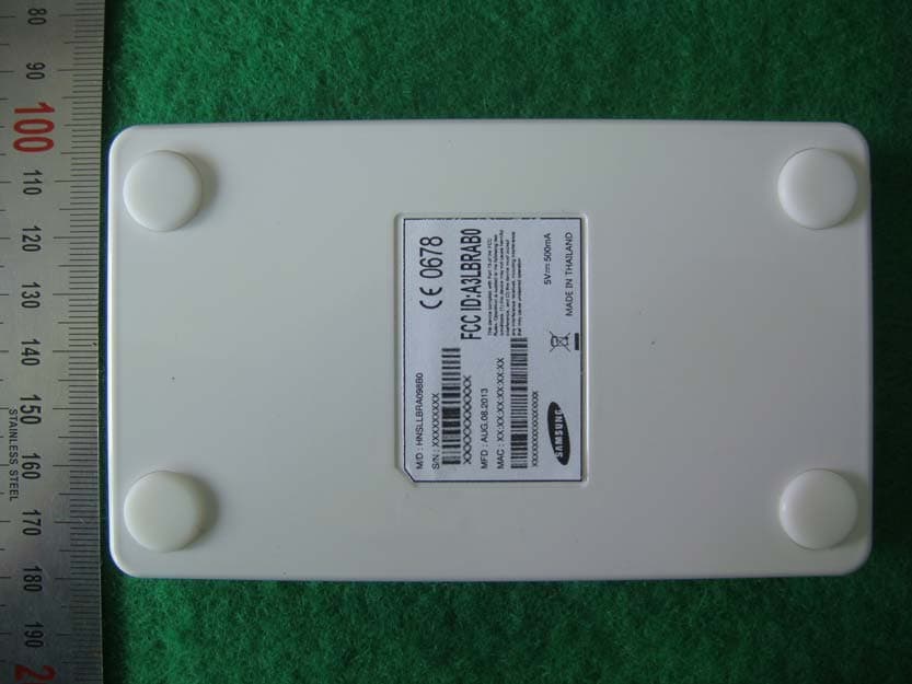
Click to zoom
Application Details
- Equipment Class
- DTS - Digital Transmission System
- Date of Grant
- Sep 16, 2013
- Application Purpose
- Original Equipment
- Date of Application
- Sep 16, 2013
- Equipment Note
- ZigBee to IP Bridge
- Frequency Range
- 2405.00000000 - 2475.00000000
- Company
- Samsung Electronics Co Ltd
- Country
- United States
Documents & Files
Document Text
Text extracted from the exhibit documents filed with the FCC. Open a document above to read the original.
Users Manual
Samsung Smart Kit User’s Guide Samsung Smart Kit 2 Version Date Description Person in charge 0.3 2013. 07. 24 Draft of Korean version released. This document is a user’s guide to introduce and to assist in installing and using Samsung Smart Kit. Samsung Smart Kit 3 Contents 1. Smart Kit at a Glance 1.1. Overview 1.1.1. What is Smart Kit? 1.1.2. Key Features 1.2. In the Box 1.3. Installation 2. Smart Kit Control using Smartphone 2.1. Initialization 2.1.1. Add Bridge 2.1.2. Bridge Management 2.1.2.1. Set up DHCP 2.1.2.2. Use HTTP-proxy 2.1.3. Add Smart Bulb 2.1.4. Add group 2.2. Smart Bulb Control 2.2.1. Control single bulbs individually 2.2.2. Control multiple bulbs by group (Portrait view) 2.2.3. Control multiple bulbs by group (Landscape view) 2.2.4. Set up in detail 3. Smart Kit Control on Bridge Samsung Smart Kit 4 1. Smart Kit at a Glance 1.1. Overview 1.1.1. What is Smart Kit? Samsung Smart Kit is a lighting management solution that allows you to control LED bulbs in your house using your Android smartphone. Now you can easily turn lights on and off and change the ambience in your living space with a touch of your finger. 1.1.2. Key Features Features Description Single Bulb Control To control Smart Bulbs separately Bulb Group Control To control Smart Bulbs by group Pattern Control To apply specific lighting-up patterns to Smart Bulbs Mood Control To change the lighting to create specific moods Schedule Control To schedule Smart Bulbs to turn on and off automatically Event Notification To set Smart Bulbs to notify you about activities on your smartphone, such as an incoming call, SMS, etc. Baby Care To set Smart Bulbs to turn on automatically if a baby cries Night Care To set Smart Bulbs to turn on when you move your smartphone Quick Panel Control To quickly control the most frequently used Smart Bulbs using the Quick Panel on your smartphone Detail Setting To optimize Smart Kit to suit your needs, controlling various functions in detail Smartphone Samsung Smart Kit 5 1.2. In the Box ( Sold separately) (Sold separately) Component Characteristics Smart Bulb 3EA - Input : AC 220-240V~ (50/60Hz) AC 100-120V~ (50/60Hz) - Socket Holder : E27 Bridge 1EA - Input : 5 V , 500 mA Adaptor 1EA - Input : AC 100-240V~ (50/60Hz) LAN Cable 1EA - General UTP Cable Smart Phone App. - Android based Application 1.3. Installation STEP 1 : Put a Smart Bulb into the socket and turn on the power. STEP 2 : Connect the bridge to the adaptor using a DC connector, and plug the AC Connector into the power socket. STEP 3 : Connect the bridge to the AP (Access Point) using the LAN Cable. STEP 4 : Download the ‘Samsung Smart Kit’ App form ‘Google play Store’ and install it onto your smartphone. Samsung Smart Kit 6 2. Smart Kit Control using Smartphone 2.1. Initialization 2.1.1. Add Bridge [1] Tap ‘Add bridge’ from the ‘Settings’ menu. To access the ‘Settings’ menu, press (or touch) the Menu button on your smartphone. [2] Take the QR code of the bridge to be added. Samsung Smart Kit 7 2.1.2. Bridge Management 2.1.2.1. Set up DHCP [1] Tap ‘My bridge’ from the ‘Settings’ menu. [2] The default value of DHCP is ‘ON’. To set up DHCP manually, tap ‘ON’ to become ‘OFF’, and then hidden functions appear. [3] Tap ‘IP address’ and a dialog pops up. [4] Enter the IP address of the bridge and tap ‘OK’. Set up the NetMask and Gateway in the same way. Samsung Smart Kit 8 2.1.2.2. Use HTTP-proxy [1] Tap ‘My bridge’ from the Settings menu. [2] The default value of HTTP-proxy is ‘OFF’. To use HTTP-proxy, tap ‘OFF’ to become ‘ON’, and then the Server and Port options appear below. [3] Tap ‘Server’. [4] Enter the IP address of the server and tap ‘OK’. Set up the Port in the same way. Samsung Smart Kit 9 2.1.3. Add Smart Bulb [1] Tap ‘Add LED’ from the Settings menu. [2] Tap ‘Add new bulb’. Samsung Smart Kit 10 2.1.4. Add group [1] Tap ‘Add group’ from the Settings menu. [2] Type the name of a new group into the ‘Group name’ field. [3] Tap ‘Add/Delete’. [4] Leave the bulbs to be added checked with √, and uncheck the others. [5] Tap ‘OK’. [6] Tap √. Samsung Smart Kit 11 2.2. Smart Bulb Control 2.2.1. Control single bulbs individually [1] Tap the single bulb icon on the top. [2] To turn all registered bulbs on and off, tap ‘ALL LIGHT’. [3] To turn a single bulb on and off, tap its icon on the left-hand side. [4] To add each bulb to the Quick panel, tap its star icon. Samsung Smart Kit 12 [5] To change the images of lights, touch and hold the light icon to be changed and then select a preferred image from the list shown. [6] To change the viewing style to the extended mode , so you can see it in detail, tap it. [7] Mood indicator, which shows the current mood – Sleep, Movie, Cook or Reading. [8] Schedule indicator, which shows whether it is set up or not – Enable or Disable. [9] Event Notification indicator, which shows whether it is set up or not – Enable or Disable. [10] Care indicator, which shows whether it is set up or not – Enable or Disable. [11] To adjust their brightness and dim lights, touch the light image and drag your finger up or down on it. [12] To change the viewing style to the extended mode, so you can see more lights on the list, tap it. [13] Tap the name of a light to enable a more detailed set up. See ‘2.2.4. Set up in detail’. Samsung Smart Kit 13 2.2.2. Control multiple bulbs by group (Portrait view) [1] Tap the multiple bulbs icon on the top. [2] To turn all groups of bulbs on and off, tap ‘ALL LIGHT’. [3] To turn each group on and off, tap its icon of the left-hand side. [4] To add each group to the Quick panel, tap its star icon. [5] To change the images of lights, touch and hold the light icon to be changed, and then select a preferred image from the list shown. [6] To change the view style to the extended mode, so you can see it in detail, tap it. [7] Mood indicator, which shows the current mood – Sleep, Movie, Cook or Reading. [8] Schedule indicator, which shows whether it is set up or not – Enable or Disable.…
Text truncated - open the document above for the full version.
External Photos
SK Tech Co., Ltd. Page 1 of 3 Photographs of EUT External view DC IN Ethernet SK Tech Co., Ltd. Page 2 of 3 Reset SK Tech Co., Ltd. Page 3 of 3
ID Label/Location Info
ID Label Location & Sample LABEL LOCATION: LABEL will be attached to the bottom of the product LABEL Drawing:
Internal Photos
SK Tech Co., Ltd. Report No.: SKTEFC-130905-012 Page 1 of 2 Photographs of EUT Cover opened SK Tech Co., Ltd. Report No.: SKTEFC-130905-012 Page 2 of 2 Main board
RF Exposure Info
RF Exposure requirements Product name ZigBee to IP Bridge Model number HNSLLBRA098B0 FCC ID A3LBRAB0 Radio specification 2.4 GHz ZigBee transceiver Antenna 2.4 GHz, Omni-directional antenna Power source DC 5 V The product is for contolling the LED lamp via ZigBee Technology. It is normally used with the minimum separation distance of 20 cm. Therefore the product can be categorized as mobile device. As the worst case according to the KDB 447498, the following standalone SAR test exclusion was considered to qualify for the SAR test exclusion. Tx frequency range 2405 MHz - 2475 MHz Device category Fixed installation (mobile device) Maximum conducted output power 9.51 mW (9.78 dBm) SAR test exclusion thresholds: [(max. power of channel, mW) / (min. separaƟon distance, mm ] · √f (GHz) ≤ 3.0 for 1‐g SAR and ≤ 7.5 for 10‐g extremity SAR MHz 5 10 15 20 25 30 35 40 45 50 test separation distance (mm) 2450 10 19 29 38 48 57 67 77 86 96 SAR test exclusion threshold (mW) The source-based time-averaged maximum conducted output power of the RF channel is less than 10 mW,, and the minimum separation distance of 5 mm can be achived. Therefore the transmitter complies with the RF exposure requirements and the SAR is not required. Antenna Position 9 mm
Test Report
SK Tech Co., Ltd. Report No.: SKTRFC-130905-012 Page 2 of 28 Revision History of Report Rev. Revisions Effect page Reviewed by Date - Initial issue All Jongsoo Yoon September 5, 2013 SK Tech Co., Ltd. Report No.: SKTRFC-130905-012 Page 3 of 28 TABLE OF CONTENTS 1 Summary of test results ................................................................................................. 4 2 Description of equipment under test (EUT) .................................................................. 5 3 Test and measurement conditions ................................................................................ 6 3.1. Test configuration (arrangement of EUT) ................................................................................ 6 3.2. Description of support units (accessory equipment)................................................................ 6 3.3. Interconnection and I/O cables................................................................................................ 6 3.4. Measurement Uncertainty (U) ................................................................................................. 6 3.5. Test date .................................................................................................................................. 6 4 Facilities and accreditations .......................................................................................... 7 4.1. Facilities................................................................................................................................... 7 4.2. Accreditations .......................................................................................................................... 7 4.3. List of test and measurement instruments............................................................................... 7 5 Test and measurements ................................................................................................. 8 5.1. Antenna requirement ............................................................................................................... 8 5.2. 6 dB bandwidth........................................................................................................................ 9 5.3. Maximum peak output power ................................................................................................ 11 5.4. Spurious emissions, Band edge, and Restricted bands ........................................................ 13 5.5. Peak power spectral density.................................................................................................. 24 5.6. AC power line conducted emissions...................................................................................... 26 SK Tech Co., Ltd. Report No.: SKTRFC-130905-012 Page 4 of 28 1 Summary of test results Requirement CFR 47 Section Result Antenna Requirement 15.203, 15.247(b)(4) Meets the requirements 6dB Bandwidth 15.247(a)(2) Meets the requirements Maximum Peak Output Power 15.247(b)(3), (4) Meets the requirements Spurious Emission, Band Edge, and Restricted bands 15.247(d), 15.205(a), 15.209(a) Meets the requirements Peak Power Spectral Density 15.247(e) Meets the requirements AC power line Conducted emissions 15.207(a) Meets the requirements SK Tech Co., Ltd. Report No.: SKTRFC-130905-012 Page 5 of 28 2 Description of equipment under test (EUT) Product: ZigBee to IP Bridge Model: HNSLLBRA098B0 Serial number: None (prototype) Model differences: Model name Difference Tested (checked) HNSLLBRA098B0 Original Note: All the differences were compared with the test sample. Technical data: Power source DC 5.0 V Local Oscillator or X-Tal 24 MHz, 25 MHz, 32 MHz Transmit Frequency 2405 MHz to 2475 MHz (15 CH) Antenna Type Omni-directional antenna Type of Modulation OQPSK RF Output power 9.78 dBm (measured conducted RF power) I/O port Type Q'ty Remark DC power input USB interface 1 LAN RJ45, Ethernet interface 1 Equipment Modifications none Submitted Documents Block diagram Schematic diagram Antenna Specification Part List User manual SK Tech Co., Ltd. Report No.: SKTRFC-130905-012 Page 6 of 28 3 Test and measurement conditions 3.1. Test configuration (arrangement of EUT) The measurements were taken in continuous transmitting mode provided by the applicant. 2405 ~ 2475 MHz Notebook PC EUT Ethernet interface AC Adapter #1 AC Adapter #2 AC Mains 3.2. Description of support units (accessory equipment) The following support units or accessories were used to form a representative test configuration during the tests. # Equipment Manufacturer Model No. Serial No. 1 Notebook PC ** SAMSUNG NT530U4C HXL991FD300407W 2 AC Adapter #1 (for Notebook PC) LISHIN PA-1600-66 CNBA4400242AD2VH31C0BYC 3 AC Adapter #2 (for EUT) Dongguan Samsung Electro -mechanics Co., Ltd. ETA-U90KWK SE1CC18AS/B-E Note: 1) For control of the RF module via Ethernet interface in the EUT. 2) The AC Adapter was provided by the applicant for the purpose of testing. 3.3. Interconnection and I/O cables The following support units or accessories were used to form a representative test configuration during the tests. Start End Cable # Name I/O port Name I/O port length (m) shielded (Y/N) 1 EUT USB AC Adapter #2 DC OUT 1.5 N 2 EUT LAN Notebook PC LAN 2.0 N 3 Notebook PC DC IN AC Adapter #1 DC OUT 1.8 N 4 AC Adapter #1 AC IN AC Mains AC Mains 1.6 N 5 AC Adapter #2 AC IN AC Mains AC Mains 1.0 N Note: 1) All the equipment/cables were placed in the worst-case configuration to maximize the emission during the test. 2) Grounding was established in accordance with the manufacturer’s requirements and conditions for the intended use. 3.4. Measurement Uncertainty (U) Measurement Item Combined Standard Uncertainty Uc Expanded Uncertainty U = k Uc (k = 2) Conducted RF power ±1.49 dB ±2.98 dB Radiated disturbance ±2.30 dB ±4.60 dB Conducted disturbance ±1.96 dB ±3.92 dB 3.5. Test date Date Tested August 22, 2013 – September 2, 2013 SK Tech Co., Ltd. Report No.: SKTRFC-130905-012 Pa…
Text truncated - open the document above for the full version.
Test Setup Photos
SK Tech Co., Ltd. Report No.: SKTEFC-130905-012 Page 1 of 4 Photographs of the test set-up Radiated emissions - front view Radiated emissions - rear view SK Tech Co., Ltd. Report No.: SKTEFC-130905-012 Page 2 of 4 Radiated emission test below 30 MHz Radiated emission test below 1 GHz SK Tech Co., Ltd. Report No.: SKTEFC-130905-012 Page 3 of 4 Radiated emission test above 1 GHz SK Tech Co., Ltd. Report No.: SKTEFC-130905-012 Page 4 of 4 AC Power line conducted emissions - front view AC Power line conducted emissions - rear view
Contact Information
Applicant
Jenni Chun(General Manager)
Test Firm
SK Tech Co., LTD.Yoon Jongsoo
Technical Specifications
| # | Rule Parts | Frequency Range | Power Output |
|---|---|---|---|
| 1 | 15C | 2.40 GHz - 2.48 GHz | 9.51 mW |
Other Applications from Samsung Electronics Co Ltd
A3LSMS741B
Aug 05, 2026Portable Handset
Equipment Class
6VL - 15E 6 GHZ Very Low Power DeviceA3LSMX940
Jul 31, 2026BT,BLE Tablet DTS,UNII a,b,g,n,ac,ax,be and digitizer
Equipment Class
DTS - Digital Transmission SystemA3LSMS741U
Jul 30, 2026Portable Handset
Equipment Class
6CD - 15E 6 GHz Low Power Dual ClientA3LSMX840
Jul 27, 2026BT,BLE Tablet DTS,UNII a,b,g,n,ac,ax and Digitizer
Equipment Class
DSS - Part 15 Spread Spectrum TransmitterA3LSMX848U
Jul 27, 2026WCDMA, LTE, 5G NR Tablet BT,BLE, DTS,UNII a b g n ac ax and Digitizer
Equipment Class
JBP - Part 15 Class B Computing Device Peripheral