A3LCLP550NLaser Beam Printer
Samsung Electronics Co Ltd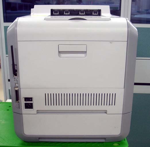
Click to zoom
Application Details
- Equipment Class
- JBP - Part 15 Class B Computing Device Peripheral
- Date of Grant
- Nov 25, 2003
- Application Purpose
- Original Equipment
- Date of Application
- Nov 25, 2003
- Equipment Note
- Laser Beam Printer
- Company
- Samsung Electronics Co Ltd
- Country
- United States
Documents & Files
Document Text
Text extracted from the exhibit documents filed with the FCC. Open a document above to read the original.
Users Manual
COLOR LASER PRINTER Setup Guide COLOR LASER PRINTER Setup Guide CLP-550 CLP-550N S ETUP G UIDE 2 C ONTENTS Step 1. Unpacking ............................................. 3 Step 2. Understanding Your Printer ................... 5 Step 3. Installing the Imaging Unit, Transfer Belt and Toner Cartridges ............................. 7 Step 4. Loading Paper ..................................... 16 Step 5. Connecting a Printer Cable .................. 19 Using a Parallel Cable .................................19 Using a USB Cable .....................................20 For Networking Printing ..............................21 Step 6. Turning the Printer On ........................ 22 Step 7. Printing a Demo Page .......................... 23 Step 8. Changing the Display Language .......... 23 Step 9. Installing the Printer Software ............ 24 Installing Printer Software in Windows ..........24 Reinstalling Printer software ........................26 Removing Printer software ..........................26 Changing the Display Language ...................26 Step 10. Viewing the User’s Guide ................... 27 In Windows ..............................................27 In Macintosh .............................................27 In Linux ...................................................28 S ETUP G UIDE 3 English Step 1. Unpacking 1 Remove the printer and all of the accessories from the packing carton. Make sure that the printer has been packed with the following items: N OTES : • If any items are missing or damaged, notify your dealer immediately. • Components may differ from one country to another. • The CD-ROM contains the printer driver, the User’s Guide, and the Adobe Acrobat Reader program. • The power cord may be different depending on your country. C AUTION : This printer weighs 35kg including developer cartridge and cassette. Use safe lifting and handling techniques. If you need to move the printer it must be moved by two people. Use the lifting handles located as shown in the diagram (see page 5). Back injury could be caused if a single person attempts to lift the printer. Toner CartridgesPower CordTransfer Belt Imaging UnitCD-ROM Setup Guide SyncThru CD-ROM (CLP-550N only) SyncThru Quick Guide (CLP-550N only) S ETUP G UIDE 4 2 Carefully remove all of the packing tapes from the printer. 3 Pull the paper tray out of the printer and remove the packing tapes from the tray. 4 Select a location for the printer: •Leave enough room to open the printer trays, covers, and allow for proper ventilation. •Provide the proper environment: – A firm, level surface – Away from direct airflow of air conditioners, heaters, or ventilators – Free of temperature, sunlight, or humidity extremes or fluctuations – Clean, dry, and free of dust C AUTION : You must place your printer in the level surface. If you do not, the print quality problems can occur. S ETUP G UIDE 5 English Step 2. Understanding Your Printer These are the main components of your printer: Output Support Control Panel (refer to Chapter 5 in the User’s Guide which is on the CD- ROM.) Paper Output Tray Top Cover (Open to install the imaging unit, and transfer belt.) Front Cover (Open to replace the waste toner bin.) Left Cover (To install the toner cartridges press the top cover release button and open fully.) Tray 1 (250-sheet paper feeder) Top Cover Release Button Optional Tray 2 (500-sheet paper feeder) Handle (Lifting handles are located at the lower edge of both sides of the printer.) S ETUP G UIDE 6 Optional Tray 2 Jam Cover (Open to remove jams in the optional tray 2.) Muti-purpose Tray (Open to load special print materials.) Right Cover (Open to remove paper jams.) Power Switch USB Port Power Receptacle Control Board Cover (Open to install optional accessories.) Wireless Network Antenna * Network Port** Parallel Port*** * This wireless network port is not supplied with the printer. It is an option that must be purchased and installed separately. ** The network port is fitted as standard on the CLP-550N. CLP-550 users can purchase and install separately an optional Network Card. For details, see the User's Guide of the printer in the CD-ROM. *** The parallel port may not be available depending on your country. Handle (Use it to lift the printer.) S ETUP G UIDE 7 English Step 3. Installing the Imaging Unit, Transfer Belt and Toner Cartridges 1 Using the handle, completely open the left cover until it is at right angles to the main frame. C AUTION : If the left cover is not completely open, the top cover release button does not press. 2 Press the top cover release button to unlatch the top cover and open it all the way. Top cover release button S ETUP G UIDE 8 3 Take the imaging unit out of the package using the handle. 4 Remove the paper covering the imaging unit by removing the tape under the handle of the imaging unit. CAUTIONS: • Do not use sharp objects, such as a knife or scissors, to open the imaging unit package and tape on the protective paper liner. You could damage the surface of the imaging unit. • To prevent damage, do not expose the imaging unit to light for more than a few minutes. Cover it with black paper, if necessary. • Do not touch the surface of the green roller on the imaging unit or print quality problems can occur. 5Locate the imaging unit slots inside the printer, one on each side. SETUP GUIDE 9 English 6Hold the handle on the imaging unit with the green roller facing you. Align the imaging unit with the slots in your printer so that the colors on both sides of the imaging unit slide into the corresponding colors of the slots. CAUTION: Insert the imaging unit carefully so as not to scratch and damage the surface of the green roller. 7Slide the imaging unit down into the printer until it cannot be pushed in any further and fold the handle down. CAUTION: To prevent damage, do not expose the imaging unit to light for more than a few minutes. Close the top and left cover should the setup need to be halted for …
Text truncated - open the document above for the full version.
Users Manual
MAINTAINING YOUR PRINTER 6.12 3Remove the container’s caps which are attached as shown below and use them to close the waste toner container. 4Take a new waste toner container out of the package. 5Insert the lower of the new container into place and then push it to make sure that it is seated in place. 6Make sure that the lock lever latches the container. MAINTAINING YOUR PRINTER 6.13 6 7Close the front cover. Make sure that the cover is securely latched. 8Using the handle, completely open the left cover until it is at right angles to the main frame and the toner cartridges are ejected. 9 Close the left cover firmly. MAINTAINING YOUR PRINTER 6.14 Replacing the Imaging Unit The life of the imaging unit is approximately 50,000 images. Replace the imaging unit when the printer control panel displays ‘Replace Imaging Unit’. 1Turn the printer off, then wait a few minutes for the printer to cool. 2Using the handle, completely open the left cover until it is at right angles to the main frame and the toner cartridges are ejected. CAUTION: If the left cover is not completely open, the top cover release button does not press. MAINTAINING YOUR PRINTER 6.15 6 3Press the top cover release button to unlatch the top cover and open it all the way. 4Pull the lock levers on each side towards you, as shown below, to release the transfer belt. MAINTAINING YOUR PRINTER 6.16 5Using the handle, lift the transfer belt out of the printer by lightly pulling it towards the left of the printer. Set it on a clean flat surface. 6Lift the handle of the used imaging unit and use it to pull the imaging unit out of the printer. MAINTAINING YOUR PRINTER 6.17 6 7Take a new imaging unit out of the package using the handle. 8Remove the paper covering the imaging unit by removing the tape under the handle of the imaging unit. CAUTIONS: • Don’t use sharp objects, such as a knife or scissors, to open the imaging unit package and tape on the protective paper liner. You could damage the surface of the imaging unit. • To prevent damage, do not expose the imaging unit to light for more than a few minutes. Cover it with black paper, if necessary. • Close the top and left cover should the setup need to be halted for any reason. • Do not touch the surface of the green roller on the imaging unit or print quality problems can occur. 9Locate the imaging unit slots inside the printer, one on each side. MAINTAINING YOUR PRINTER 6.18 10Hold the handle of the new imaging unit with the green roller facing you. Align the imaging unit with the slots in your printer so that the colors on both sides of the imaging unit slide into the corresponding colors of the slots. CAUTION: Insert the imaging unit carefully so as not to scratch and damage the surface of the green roller. 11 Slide the imaging unit down into the printer until it cannot be pushed in any further and fold the handle down. MAINTAINING YOUR PRINTER 6.19 6 12To replace the transfer belt, hold its handle and then align it with the slots inside your printer, on each side. NOTE: Do not turn the transfer belt over. If you do this, the toner may spill. 13Slide the transfer belt down into the printer and press it firmly into place. MAINTAINING YOUR PRINTER 6.20 14Firmly push the lock levers on each side towards the top cover, as shown below, to lock the transfer belt into place. 15After making sure that the left cover is open, close the top cover. Make sure that it is securely latched. CAUTION: Do not try to close the left cover with the top cover open. This may cause damage to the printer. MAINTAINING YOUR PRINTER 6.21 6 16 Close the left cover firmly. 17Turn the printer on. 18In ready mode press the Menu button ( ) on the control panel until you see ’Setup’ on the bottom line of the display. 19Press the Enter button ( ) to access the menu. 20Press the scroll button ( or ) until ‘Maintenance’ displays on the bottom line and press the Enter button (). 21Press the scroll button ( or ) to until ‘Check Others’ displays on the bottom line and press the Enter button (). 22Press the scroll button ( or ) to until ‘Imaging Unit’ displays on the bottom line and press the Enter button (). 23Press the scroll button ( or ) to display ‘Reset’ and press the Enter button ( ). 24‘Reset Now’ appears on the bottom line of the display and the printer returns to the ready mode. NOTE: After replacing the imaging unit, you must reset the image counter for the imaging unit. If you do not this, ‘Replace Imaging Unit’ continuously appears on the display. MAINTAINING YOUR PRINTER 6.22 Replacing the Transfer Belt The life of the transfer belt is approximately 50,000 images. Replace the transfer belt when the control panel displays ‘Replace Transfer Belt’. To replace the transfer belt: 1Turn the printer off, then wait a few minutes for the printer to cool. 2Using the handle, completely open the left cover until it is at right angles to the main frame and the toner cartridges are ejected. CAUTION: If the left cover is not completely open, the top cover release button does not press. MAINTAINING YOUR PRINTER 6.23 6 3Press the top cover release button to unlatch the top cover and open it all the way. 4Pull the lock levers on each side towards you, as shown below, to release the transfer belt. MAINTAINING YOUR PRINTER 6.24 5Using the handle, lift the used transfer belt out of the printer by lightly pulling it towards the left of the printer. NOTE: Keep the transfer belt level, do not turn the transfer belt over otherwise looses toner may be spilled. 6Take a new transfer belt out of the package. 7Remove the paper covering the transfer belt by removing the tape. CAUTION: Don’t use sharp objects, such as a knife or scissors, to open the transfer belt package. You could damage the surface of the transfer belt. MAINTAINING YOUR PRINTER 6.25 6 8Pinch the transfer belt tention levers on both sides of the transfer belt. Then, pull them out, as shown below. 9Locate the transfer belt slots inside the printer, one on each side. CAUT…
Text truncated - open the document above for the full version.
Block Diagram
SPC603e 266MHz SPC603e 266MHz SPGPi SPGPi Panel 16x2 LCD Panel 16x2 LCD SDRAM 64(128)MB SDRAM 64(128)MB EEPROM 1KB EEPROM 1KB LPEC1 EngineControl ASIC LPEC1 EngineControl ASIC Flash Memory 8MB Flash Memory 8MB NPC Wire/Wireless Optional NPC Wire/Wireless Optional USB2.0 USB2.0 IEEE1284 IEEE1284 UART for debug UART for debug Engine Mecha Engine Mecha System Bus 32-bit,50MHz Memory Bus 32-bit,50MHz UART Flash DIMM Optional Flash DIMM Optional SDRAM DIMM Optional:64,128,256MB SDRAM DIMM Optional:64,128,256MB CLP-550/550N Block-diagram CLP-550/550N Block-diagram PC PANEL B’D OSC 12.5MHz OSC 19.9MHz Main Clock Video Clock HIC Super1284 NPC Optional Board Flash Memory 29LV320 x 2 8MB SDRAM K4S561632 x 2 64MB EEPROM 93C86 1KB SDRAM DIMM Optional 64MB,128MB,256MB FLASH DIMM Optional SPC603IFT 266MB SPGPi ASIC LPEC1 USB2.0 NET2270 CS,SK,DI,DO PD0~PD7 SD0~SD31 SA0~SA12 nVDO nRD,nWR, nCS_LPEC,nRESET nRD,nWR, nNPC_CS,nNPC_IRQ D0~D31 A2~A22 D0~D7 A2~A9 D0~D31A0~A31 A2~A17 D16~D31 SA0~SA4 SD16~SD31 TT1,TSIZ,nTS,nTBST,nTA nUSB_DIOCS,nUSB_DREQ, nUSB_DACK,nDMA_OE,nDMA_WE BA0~BA1
External Photos
Front View Left View Rear View Right View To p V i e w
ID Label/Location Info
Page 17 of 18 Project NO. : LBE032387 5. FCC Label Configuration and Location 5.1 Label Configulation 5.2 Location of Label This report shall not be reproduced except in full, without the written approval of SEC EMC Testing laboratory. CLP-550N A3LCLP550N
Internal Photos
DEV_OEM Board TOP DEV_OEM Board BOTTOM DEV_Switch Board TOP DEV_Switch Board BOTTOM RAM DIMM Board TOP RAM DIMM Board BOTTOM HVPS Board TOP HVPS Board BOTTOM MAIN Board TOP MAIN Board BOTTOM PANEL Board TOP PANEL Board BOTTOM SCF Board TOP SCF Board BOTTOM SMPS Board TOP SMPS Board BOTTOM
Test Report
Page 1 of 18 Project NO. : LBE032387 Product :Laser Beam Printer Model No. : CLP-550N FCC ID : A3LCLP550N 1. This test reports shall not be reproduced except in full, without the written approval of SEC EMC Testing laboratory. 2. This test reports does not constitute an endorsement by NIST/NVLAP or U.S Government. 3. This test report is to certify that the tested device properly complies with the requirements of FCC Rules and Regulations Part 15 Subpart B Unintentional Radiators. All tests necessary to show compliance to the requirements were and these results met the specifications requirement. 4. That data in this report are traceable to National or International Standards. Date of test :Nov 21, 2003 Issued Date :Nove 21, 2003 Tested by: Jong Ho,LEE / Test Engineer Reviewed by: Choon Kil,KIM / Manager of EMC Lab. Authorised by: Kyu Baek, CHUNG / Chief of EMC Lab. This laboratory is registered by the NIST/NVLAP, U.S.A. The test reported herein have been performed in accordance with its terms of registration. EMI TEST REPORT According to FCC Part 15 Subpart B/Class B NVLAP Code: 200447 Page 2 of 18 Project NO. : LBE032387 Table of Contents 1. General Information 1.1 Product Description 1.2 Configuration of EUT and peripherals 1.3 Used Cable Description 1.4 System Block Diagram of Test Configuration 1.5 Test Facility 2. System Test Configuration 2.1 Configuration of Radiated and Conducted Interference Measurement 2.2 Operation Environment 2.3 Test Procedure 2.4 Measurement Uncertainty 3. Conducted Emission Test Data 4. Radiated Emission Test Data 5. Label Configuration and Location 6. Test Equipment Used Distribution This test report has been made available as follows: CS Management Center, EMC Laboratory1 original Printer Division1 copy This report shall not be reproduced except in full, without the written approval of SEC EMC Testing laboratory. Page 3 of 18 Project NO. : LBE032387 1. General Information Applicant :Samsung Electronics Co., Ltd. Full Address :416 Maetan 3 Dong, Paldal-Ku, Suwon City, Kyungki Do, Korea, 442-742 Kind of Product :Laser Beam Printer FCC ID:A3LCLP550N Project Name :- Model & Variant Names : CLP-550 Brand : Samsung - Basic Model - Option: IEEE802.11,10/100 BaseTX Ethernet - Memory : 64MB Test Report Produced by : Jong Ho,LEE / Test Engineer This report shall not be reproduced except in full, without the written approval of SEC EMC Testing laboratory. Page 4 of 18 Project NO. : LBE032387 1.1 Product Description 1) Justification The system was configured for testing in typical fashion use. Cable were attached to each of the available I/O Ports. Where applicable, peripherals were attached to the I/O cables. The mode of operation utilized for testing was selected to best simulate typical EUT use. In each test mode, Finally we found worst case emission that is above configuration with the Worst case components(in the above table). So, the DATA of the maximum EUT operation was reported. Further details of cabling and configuration are shown in the test system configuration. 2) Operating Frequency : CLP-550N is supporting the IEEE1284,USB,LAN,WireLess LAN Printing Mode. CLP-550N model have Video : 19.000614MHz,CPU:12.5MHz(Clock),LPEC clock:19.00064MHz USB clock:30MHz,N/W clock:25MHz Wireless LAN BW:2.4GHz This report shall not be reproduced except in full, without the written approval of SEC EMC Testing laboratory. Page 5 of 18 Project NO. : LBE032387 3) Description of Testing operating mode USB PrintingContinously H pattern printing by Computer IEEE1284 PrintingContinously H pattern printing by Computer Continously H pattern Receiving and Transmitting Continously H pattern Copying EUT was tested all operating mode as above. Finally EUT was tested USB Printing mode as maximum emission.But all ports are activity and connected. 4) Tested Resolution : 5) Manufacturer :SAMSUNG Electronics Co., Ltd. This report shall not be reproduced except in full, without the written approval of SEC EMC Testing laboratory. Wireless LAN Printing Tested Video modeResolutionsRefresh rates Operating Mode Operating section of EUT LAN Printing Colors Page 6 of 18 Project NO. : LBE032387 1.2 Configuration of EUT and peripherals MarkItemModel No.Serial No.ManufacturerRemark A Laser Beam Printer CLP-550N-SamsungEUT BComputer Blade1729 DELLDoC CAdaptor PA150005D CN00R3344801028600E0 DELLDoC DMouse SAW34LZC23500714 LogitechDZL211029 EMouse C3KMS11022949 MicrosoftDoC This report shall not be reproduced except in full, without the written approval of SEC EMC Testing laboratory. Page 7 of 18 Project NO. : LBE032387 1.3 Used Cable Description No.ItemLength[m]Shielded (Y/N)Remark 1AC Power Cable1.7N- 2LAN2.0Y- 3USB Cable1.5Y- 4Parallel Cable1.5Y- 5AC Power Cable1.5N- This report shall not be reproduced except in full, without the written approval of SEC EMC Testing laboratory. Page 8 of 18 Project NO. : LBE032387 1.4 System Block Diagram of Test Configuration 1.5 Test Facility All test described in this report were performed by : SAMSUNG ELECTRONICS CO., LTD. EMC TESTING LABORATORY 416 Maetan 3 Dong, Paldal-Ku, Suwon City, Kyungki Do, Korea, 442-742 Semi Anechoic Chamber #2(Registration Number:873282) and Shielded Room. This test facility has been filed in FCC under the criteria in ANSI C63.4-1995. This report shall not be reproduced except in full, without the written approval of SEC EMC Testing laboratory. AC A B Parallel USB LAN Wireless Wireless C D E Page 9 of 18 Project NO. : LBE032387 2. System Test Configuration 2.1 Configuration of Radiated and Conducted Interference Measurement * Cabling was taken into consideration and test data was taken under worse case conditions. 1)Conduction(Front View) 2)Conduction(Rear View) This report shall not be reproduced except in full, without the written approval of SEC EMC Testing laboratory. Page 10 of 18 Project NO. : LBE032387 3) Radiation(Front View) This report shall not be reproduced except in full, without the written approval of SEC EMC Testing labor…
Text truncated - open the document above for the full version.
Test Setup Photos
Page 9 of 18 Project NO. : LBE032387 2. System Test Configuration 2.1 Configuration of Radiated and Conducted Interference Measurement * Cabling was taken into consideration and test data was taken under worse case conditions. 1)Conduction(Front View) 2)Conduction(Rear View) This report shall not be reproduced except in full, without the written approval of SEC EMC Testing laboratory. Page 10 of 18 Project NO. : LBE032387 3) Radiation(Front View) This report shall not be reproduced except in full, without the written approval of SEC EMC Testing laboratory.
Contact Information
Applicant
Jenni Chun(General Manager)
Technical Contact
PCTEST Engineering Lab., Inc.Randy Ortanez
[email protected]410-290-6652
6660-B Dobbin Road · Columbia, Maryland · United States
Test Firm
SAMSUNG ELECTRONICS CO., LTD.No Cheon Park
Technical Specifications
| # | Rule Parts | Frequency Range | Power Output |
|---|---|---|---|
| 1 | 15B | - | - |
Other Applications from Samsung Electronics Co Ltd
A3LSMS741B
Aug 05, 2026Portable Handset
Equipment Class
6VL - 15E 6 GHZ Very Low Power DeviceA3LSMX940
Jul 31, 2026BT,BLE Tablet DTS,UNII a,b,g,n,ac,ax,be and digitizer
Equipment Class
DTS - Digital Transmission SystemA3LSMS741U
Jul 30, 2026Portable Handset
Equipment Class
6CD - 15E 6 GHz Low Power Dual ClientA3LSMX840
Jul 27, 2026BT,BLE Tablet DTS,UNII a,b,g,n,ac,ax and Digitizer
Equipment Class
DSS - Part 15 Spread Spectrum TransmitterA3LSMX848U
Jul 27, 2026WCDMA, LTE, 5G NR Tablet BT,BLE, DTS,UNII a b g n ac ax and Digitizer
Equipment Class
JBP - Part 15 Class B Computing Device Peripheral