A3LDC60CPSLaser Printer
Samsung Electronics Co Ltd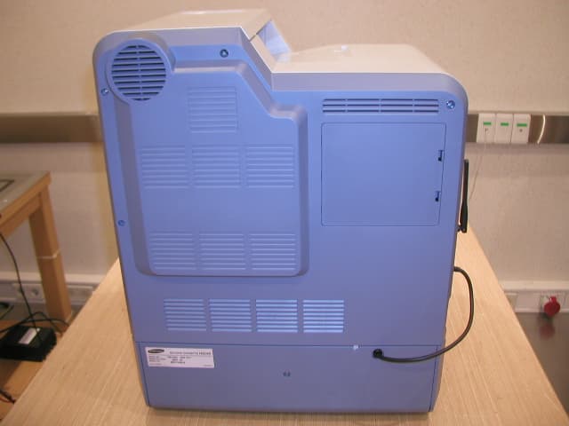
Click to zoom
Application Details
- Equipment Class
- JBP - Part 15 Class B Computing Device Peripheral
- Date of Grant
- Aug 31, 2005
- Application Purpose
- Original Equipment
- Date of Application
- Aug 31, 2005
- Equipment Note
- Laser Printer
- Company
- Samsung Electronics Co Ltd
- Country
- United States
Documents & Files
Document Text
Text extracted from the exhibit documents filed with the FCC. Open a document above to read the original.
Users Manual
This manual is provided for information purposes only. All information included herein is subject to change without notice. Samsung Electronics is not responsible for any changes, direct or indirect, arising from or related to use of this manual. © 2005 Samsung Electronics Co., Ltd. All rights reserved. • CLP-600 and CLP-600N are model names of Samsung Electronics Co., Ltd. • SAMSUNG and Samsung logo are trademarks of Samsung Electronics co., Ltd. • Apple, TrueType, Laser Writer, and Macintosh are Trademarks of Apple Computer, Inc. • Microsoft, Windows, Windows 98SE, Windows Me, Windows 2000, Windows 2003, Windows NT 4.0, and Windows XP are registered trademarks of Microsoft Corporation. • All other brand or product names are trademarks of their respective companies or organizations. About the User’s Guide This User’s Guide provides information you need for setting up your printer. It also provides all of the detailed instructions for using your printer and information for maintaining and troubleshooting the printer. The Software User’s Guide, which is the second section of this guide, provides information you need for installing the supplied software and using its features. ii CONTENTS 1. Introduction Special Features .................................................................................................................... 1.1 Printer Components ................................................................................................................ 1.2 Front View ....................................................................................................................... 1.2 Right Side View ................................................................................................................ 1.2 2. Setting Up Your Printer Unpacking ............................................................................................................................. 2.1 Installing the Toner Cartridges ................................................................................................. 2.2 Loading Paper ....................................................................................................................... 2.4 Changing the Size of the Paper in the Tray ........................................................................... 2.5 Connecting a Printer Cable ...................................................................................................... 2.6 For Local Printing .............................................................................................................. 2.6 For Network Printing (CLP-600N only) ................................................................................. 2.7 Turning the Printer On ............................................................................................................ 2.7 Printing a Demo Page ............................................................................................................. 2.7 Changing the Display Language (CLP-600N Only) ....................................................................... 2.8 Installing the Printer Software ................................................................................................. 2.8 System Requirements ....................................................................................................... 2.8 Printer Driver Features ...................................................................................................... 2.9 3. Using the Control Panel Understanding the Control Panel .............................................................................................. 3.1 Display (CLP-600N Only) ................................................................................................... 3.1 Buttons ........................................................................................................................... 3.2 Using Control Panel Menus (CLP-600N Only) .............................................................................. 3.2 Accessing Control Panel Menus ........................................................................................... 3.2 Overview of Control Panel Menus ........................................................................................ 3.3 Information Menu ............................................................................................................. 3.3 Color Menu ...................................................................................................................... 3.3 Printer Menu .................................................................................................................... 3.4 Setup Menu ..................................................................................................................... 3.4 Network Menu .................................................................................................................. 3.5 4. Using Print Materials Choosing Paper and Other Materials ......................................................................................... 4.1 Sizes and Capacities ......................................................................................................... 4.1 Guidelines for Paper and Special Materials ........................................................................... 4.1 Loading Paper ....................................................................................................................... 4.2 Using Tray 1 .................................................................................................................... 4.2 Using the Optional Tray ..................................................................................................... 4.2 Using the Multi-purpose Tray ............................................................................................. 4.2 Using the Manual Feed ............................................................................…
Text truncated - open the document above for the full version.
Users Manual
Solving Problems 7.6 CAUTION: • Do not touch the green surface, the OPC drum, on the front of each toner cartridge with your hands or any other material. Use the handle on each cartridge in order to avoid touching this area. • Be careful not to scratch the surface of the paper transfer belt. • If you leave the access door open for more than a few minutes, the OPC drum can be exposed to light. This will cause damage to the OPC drum. Close the access door should the installation need to be halted for any reason. 3Close the access door firmly. The printer will resume printing. CAUTION: If the access door is not completely closed, the printer will not operate. Inside the Printer If paper is jammed inside the printer, a lamp turns on at the corresponding location on the Status map. If you use the CLP- 600N, “Jam Inside Printer” also appears on the display. 1Using the handle, completely open the access door. 2Open the top cover. 3Holding the inner cover open, carefully take the jammed paper out of the printer. The inner cover will then close automatically. CAUTION: • Do not touch the fuser inside the inner cover. It is hot and could cause burns! The fuser’s operating temperature is 180°C (356°F). Take care when removing paper from the printer. • Do not touch the green surface, the OPC drum, on the front of each toner cartridge with your hands or any other material. Use the handle on each cartridge in order to avoid touching this area. • Be careful not to scratch the surface of the paper transfer belt. • If you leave the access door open for more than a few minutes, the OPC drum can be exposed to light. This will cause damage to the OPC drum. Close the access door should the installation need to be halted for any reason. 4After removing the jammed paper, check for paper which may be jammed in other parts of the printer. 5After making sure that the access door is open, close the top cover. Make sure that it is securely latched. The fuser is hot! Solving Problems 7.7 6Close the access door firmly. The printer will resume printing. CAUTION: If the top cover and access door are not completely closed, the printer will not operate. In the Paper Exit Area If paper is jammed in the paper exit area, a lamp turns on at the corresponding location on the Status map. If you use the CLP-600N, “Jam In Exit Area” also appears on the display. 1If a long portion of the paper is visible, pull it straight out. Open and close the access door firmly. The printer will resume printing. If you cannot find the jammed paper, or if there is any resistance removing the paper, stop pulling and go to step 2. 2Using the handle, completely open the access door. CAUTION: • Do not touch the green surface, the OPC drum, on the front of each toner cartridge with your hands or any other material. Use the handle on each cartridge in order to avoid touching this area. • Be careful not to scratch the surface of the paper transfer belt. • If you leave the access door open for more than a few minutes, the OPC drum can be exposed to light. This will cause damage to the OPC drum. Close the access door should the installation need to be halted for any reason. 3Open the top cover. 4Holding the inner cover open, carefully take the jammed paper out of the printer. The inner cover will then close automatically. CAUTION: Do not touch the fuser inside the inner cover. It is hot and could cause burns! The fuser’s operating temperature is 180°C (356°F). Take care when removing paper from the printer. The fuser is hot! Solving Problems 7.8 5After removing the jammed paper, check for paper which may be jammed in other parts of the printer. 6After making sure that the access door is open, close the top cover. Make sure that it is securely latched. 7Close the access door firmly. The printer will resume printing. CAUTION: If the top cover and access door are not completely closed, the printer will not operate. In the Optional Tray2 If paper is jammed in the optional tray 2, a lamp turns on at the corresponding location on the Status map. If you use the CLP- 600N, “Jam0 In Tray2” also appears on the display. 1Using the handle, completely open the access door. 2Open the top cover. Solving Problems 7.9 3Holding the inner cover open, carefully take the jammed paper out of the printer. The inner cover will then close automatically. Go to step 12. If you cannot find the jammed paper, or if there is any resistance removing the paper, stop pulling and close the access door. Go to step 4. CAUTION: • Do not touch the fuser inside the inner cover. It is hot and could cause burns! The fuser’s operating temperature is 180°C (356°F). Take care when removing paper from the printer. • Do not touch the green surface, the OPC drum, on the front of each toner cartridge with your hands or any other material. Use the handle on each cartridge in order to avoid touching this area. • Be careful not to scratch the surface of the paper transfer belt. • If you leave the access door open for more than a few minutes, the OPC drum can be exposed to light. This will cause damage to the OPC drum. Close the access door should the installation need to be halted for any reason. 4Open the outer jam cover in Tray 2. 5Open the inner cover of Tray 2. Solving Problems 7.10 6Pull the jammed paper out in the direction shown. To avoid tearing the paper, pull it out gently and slowly. 7Close the two jam covers and go to step 11. If you cannot find the jammed paper, or if there is any resistance removing the paper, stop pulling and continue to step 8. 8Pull the optional tray 2 open. After you pull it all the way out, lift up the front part of the tray slightly to release the tray from the printer. 9If you see the jammed paper, remove the paper from the printer by gently pulling it straight out as shown below. 10Slide the tray back into the printer and close the two jam covers. Solving Problems 7.11 11Open the access door. 12After making sure that the access door is open. Close the top cover. 13Cl…
Text truncated - open the document above for the full version.
Block Diagram
daVinci GDI H/W Platform RM5231 250mhz RM5231 RM5231 250mhz System System Controller Controller SDRAM 32MB SDRAM 32MB Ethernet Ethernet HDD HDD Flash ROM 2MB/4MB Flash ROM 2MB/4MB Hyper-C (SEC) Hyper-C (SEC) USB2.0 USB2.0 LPEC 2 (SEC) LPEC 2 (SEC) VIDEO Y/M/C/K Engine Control USB2.0 CIP 5 (SEC) CIP 5 (SEC) PCI32-bit/30mhz 32-bit/75mhz daVinci GDI board Block Diagram +5VL Cover S/W POWER CORD Regulator +2.5V RELAY SMPS +5V Syscon V320 LPEC2 ASIC Engine control +24VF +3.3V MIPS RM5231A 250MHz EEPROM 24C04 4Kbitsx5 NPC Option Board Hyper C ASIC Flash Memory AM29LV160 2MB/4MB SDRAM K4S561632 32MB X-TAL 14.318M CLOCK Gen. Reset IC EEPROM 24C16 16Kbits UART ST16C550 USB ISP1582 CMDnINT(5)nVALIDINnVALIDOUT AD ADDR MAD PAD nINT_LANnPERR, nSERRnIRDYnCBE(4), nDEVSEL A1~A10 MAD(0~7) M U X nRD,nWRnLPEC2_CSnRESET X-TAL 24.80M STS, CMDCLK, RDY OP PANEL nVDIVCLKnPSYNC, nLSYNC Heater Thermostat Thermistor FUSER Unit AC lines Belt Unit Charge(1), T(4)AC_Vpp(4), AC_DutyDC_Duty,ATTR+ (PWM)) ATTR- , AC Enable HVPS T1 (+DC) Paper(+DC,-DC) Deve (AC+DC) CHARGE (-DC) Current sensing Charge, T, ATTR Deve RollT1 Roll Charge Roll Supply Roll T1 (+DC) ATTR Roll +24V New Fuser Analog Sensor ← Temp, RH sensor ← Color registration sensor ← System Temp ← CTD sensor(reserved) CRUM New Fuser Belt CRUM Deve K Unit CRUM Deve C Unit CRUM Deve M Unit CRUM Deve Y Unit CRUM Deve CRUM Joint B'D LSU Unit - 4LD driver- 1 Polygon motor Driver board Motor → 2 BLDC (Deve CKYM,OPC) → 1 Step motor(Fuser) Fan → Fuser,SMPS Clutch & Solenoid → Pickup, MP Pickup, Deve-C Sensor → Paper Empty(FCF, MPF) → Paper Regi (Feed) → Exit Sensor nFAN_FUSER, nFAN_SMPSnSOL_PICKUP, nSOL_MPnCLT_3_DEVEnS_EMPT, nS_MP_EMPTnS_FEED, nS_EXIT nBLDC_START, BLDC_CLKnBLDC_RDY Paper Tray (250sheets) MPF Tray (50sheets) Duplex Unit (PDL only) SCF Unit (500sheets) Belt CRUM Joint B'D
External Photos
20 of 21 Samsung EMC Laboratory Project No: LBE051902 This report shall not be reproduced except in full, without the written approval of SEC EMC Testing laboratory. 4.2 EUT Photography Picture 5. EUT (Front) Picture 6. EUT (Rear)
ID Label/Location Info
21 of 21 Samsung EMC Laboratory Project No: LBE051902 This report shall not be reproduced except in full, without the written approval of SEC EMC Testing laboratory. Picture 7. Label location Picture 8. Label location A3LDC60CPS A3LDC60CPS
Internal Photos
Fig. 01 Main PBA Fig. 02 Main Solder Fig. 03 SMPS PBA Fig. 04 SMPS Solder Fig. 05 HVPS PBA Fig. 06 HVPS Solder Fig. 07 Panel PBA Fig. 08 Panel Solder Fig. 09 Driver PBA Fig. 10 Driver Solder Fig. 11 WLAN PBA Fig. 12 WLAN Solder Fig. 13 NPC PBA Fig. 14 NPC Solder
Test Report
1 of 21 Samsung EMC Laboratory Project No: LBE051902 This report shall not be reproduced except in full, without the written approval of SEC EMC Testing laboratory. EMI Test Report According to FCC Part 15 Subpart B Project No. LBE051902 Equipment under Test Applicant Samsung Electronics Co., Ltd. 416 Maetan 3-Dong, Yeongtong-Gu, Suwon-Si, Gyeonggi-Do, Korea, 443-742 FCC ID A3LDC60CPS Product Name Laser Printer Model Name DC60CPS Manufacturer Samsung Electronics Co., Ltd. Date of Test August 5, 2005 Issued Date August 8, 2005 Name/Position Signature Tested by Kyeong Dong, Kim Test Engineer Reviewed by No Cheon, Park Manager of EMC Lab. Authorized by Seung Kyu, Cha Chief of EMC Lab. 1. This test reports does not constitute an endorsement by NIST/NVLAP or U.S Government. 2. This test report is to certify that the tested device properly complies with the requirements of FCC Rules and Regulations Part 15 Subpart B Unintentional Radiators. All tests necessary to show compliance to the requirements were and these results met the specifications requirement. This laboratory is registered by the NIST/NVLAP, U.S.A. The test reported herein have been performed in accordance with its terms of registration. 3. FCC filing Registration Number : 873282 NVLAP LAB CODE 200623-0 2 of 21 Samsung EMC Laboratory Project No: LBE051902 This report shall not be reproduced except in full, without the written approval of SEC EMC Testing laboratory. Table of Contents 1. General Information 1.1 Basic Information related Product 1.2 Detail Information related Product 1.3 Operating mode and condition 1.4 Test System Details 1.5 Equipment Modifications 1.6 Test Procedure 1.7 Test Configuration 1.8 Applied Standard 1.9 Test Facility 2. Summary of Test Results 3. Description of individual tests 3.1 Conducted Emission 3.2 Radiated Emission 4. Appendix 4.1 Test Photography 4.2 EUT Photography 3 of 21 Samsung EMC Laboratory Project No: LBE051902 This report shall not be reproduced except in full, without the written approval of SEC EMC Testing laboratory. 1. General Information 1.1 Basic Information related Product Applicant Samsung Electronics Co., Ltd. Model name DC60CPS Applicant Address 416 Maetan 3-Dong, Yeongtong-Gu, Suwon-Si, Gyeonggi-Do, Korea, 443-742 Contact Person Kyeong Dong, Kim Kind of product Laser Printer Variant list CLP-600 : Basic Model CLP-600N: with network card Manufacturer Samsung Electronics Co., Ltd. New / Alternative / Permissive change Information New 1.2 Detail Information related Product Specification Item Specification Remark Printing Speed Black and Color : Up to 20ppm in A4(21ppm in Letter) - Printing Resolution Up to 2400 x 600 dpi - Memory 32MB (not expandable) - Interface CLP-600 : USB 2.0 CLP-600N : USB 2.0, Ethernet 10/100 Base Tx Option : CLP-600N Only(Ethernet 10/100 Base Tx, 802.11 a/b/g Wireless LAN(internal)) - Power Rating AC 100~127V(USA, Canada), 10A Power Consumption 550W average during operation / Less than 35W in power Save mode - External Dimensions 465mm(W) X 465mm(D) X 445mm(H) - Operating Frequency Video(31.005MHz), SDRAM(75MHz), USB Clk(12MHz), N/W clock:25MHz, Wireless LAN(2.4GHz), SDRAM clock of network Card(133MHz) 4 of 21 Samsung EMC Laboratory Project No: LBE051902 This report shall not be reproduced except in full, without the written approval of SEC EMC Testing laboratory. 1.3 Operating Mode and Condition The system was configured for testing in typical fashion use. Cable were attached to each of the available I/O port. Where applicable, peripherals were attached to the I/O cables. This EUT have Wireless Printing server function so Host PC link to EUT and transfer print file formation "H" character document continuously. The EUT is supporting the USB, LAN and Wireless LAN printing mode. In each test mode, finally we found worst case emission that is above configuration with the worst case components(in the above table). So, the data of the maximum EUT operation, USB printing was reported. - Power Input Voltage : AC 110V Frequency : 60Hz 1.4 Test System Details Refer to 1.2 1.5 Equipment Modifications No equipment modifications were required. 5 of 21 Samsung EMC Laboratory Project No: LBE051902 This report shall not be reproduced except in full, without the written approval of SEC EMC Testing laboratory. 1.6 Test Procedure 1.6.1 Conducted Emission EUT was placed on a platform nominal size, 1m by 1.5m, raised 80cm above the conducting ground plane. The rear of tabletop was located 40cm to the vertical conducting ground plane. The rear of EUT, including peripherals was aligned and flush with rear of tabletop. All other surfaces of tabletop was at least 80cm from any other grounded conducting surface. I/O cables and AC cables that were connected to the peripherals were bundled in center. They were folded back and forth forming a bindle 30cm to 40cm long and were handed at a 40cm height to the ground plane. Each EUT current-carrying power lead, except the ground(safety)lead, were individually connected through a LISN to the input power source. All unused 50 ohm connectors of the LISN were resistively terminated in 50 ohm when not connected to the measuring equipment. Frequency Band [MHz] Instrument Detector Resolution Bandwidth Video Bandwidth Quasi-Peak 9kHz - 0.15 to 30 EMI Receiver Average 9kHz - 1.6.2 Radiated Emission EUT was placed on a platform of nominal size, 1m by 1.5m, raised 80cm above the conducting ground plane. The rear of EUT, including peripherals was aligned and flush with rear of tabletop. I/O cables that were connected to the peripherals were bundle in center. They were folded back and forth forming a bundle 30cm to 40cm long and were hanged 40cm height to the ground plane. Test was made with the antenna positioned in both the horizontal and vertical planes of polarization. The measurement antenna was varied in height above the conducting ground plane and the run table azimuth was varied to obtain the maximum signal strength 6 of 21 Samsung EMC Labor…
Text truncated - open the document above for the full version.
Test Setup Photos
18 of 21 Samsung EMC Laboratory Project No: LBE051902 This report shall not be reproduced except in full, without the written approval of SEC EMC Testing laboratory. 4. Appendix 4.1 Test Photography Picture 1. Conducted Emission (Front) Picture 2. Conducted Emission (Rear) 19 of 21 Samsung EMC Laboratory Project No: LBE051902 This report shall not be reproduced except in full, without the written approval of SEC EMC Testing laboratory. Picture 3. Radiated Emission (Front) Picture 4. Radiated Emission (Rear)
Contact Information
Applicant
Jenni Chun(General Manager)
Technical Contact
PCTEST Engineering Lab., Inc.Randy Ortanez
[email protected]410-290-6652
6660-B Dobbin Road · Columbia, Maryland · United States
Test Firm
Samsung Electronics Co., Ltd.John Lee
Technical Specifications
| # | Rule Parts | Frequency Range | Power Output |
|---|---|---|---|
| 1 | 15B | - | - |
Other Applications from Samsung Electronics Co Ltd
A3LSMS741B
Aug 05, 2026Portable Handset
Equipment Class
6VL - 15E 6 GHZ Very Low Power DeviceA3LSMX940
Jul 31, 2026BT,BLE Tablet DTS,UNII a,b,g,n,ac,ax,be and digitizer
Equipment Class
DTS - Digital Transmission SystemA3LSMS741U
Jul 30, 2026Portable Handset
Equipment Class
6CD - 15E 6 GHz Low Power Dual ClientA3LSMX840
Jul 27, 2026BT,BLE Tablet DTS,UNII a,b,g,n,ac,ax and Digitizer
Equipment Class
DSS - Part 15 Spread Spectrum TransmitterA3LSMX848U
Jul 27, 2026WCDMA, LTE, 5G NR Tablet BT,BLE, DTS,UNII a b g n ac ax and Digitizer
Equipment Class
JBP - Part 15 Class B Computing Device Peripheral