A3LKHANHIFIVideo Cassette Recorder
Samsung Electronics Co Ltd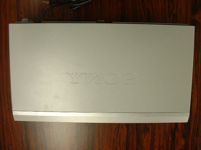
Click to zoom
Application Details
- Equipment Class
- HID - Part 15 TV Interface Device
- Date of Grant
- Nov 07, 2002
- Application Purpose
- Original Equipment
- Date of Application
- Nov 07, 2002
- Equipment Note
- Video Cassette Recorder
- Frequency Range
- 67.25000000 - 71.75000000
- Company
- Samsung Electronics Co Ltd
- Country
- United States
Documents & Files
Document Text
Text extracted from the exhibit documents filed with the FCC. Open a document above to read the original.
Users Manual
3-081-017-01 (1) US Video Cassette Recorder Operating Instructions For customers in the USA Many solutions to common problems and service information can be found at www.sony.com/vcrhelp or contact Sony VCR service at 1 (800) VHS-SONY. For all other Sony product questions, please call Sony Customer Information Services Company at 1-800-222-SONY (7669). Or write to: Sony Customer Information Services Company 12451 Gateway Boulevard Ft. Myers, FL 33913 Declaration of Conformity Trade Name: SONY Model No.: SLV-N700/N500 Responsible Party: Sony Electronics Inc. Address: 680 Kinderkamack Road Oradell, New Jersey 07649 Telephone No.:201-930-6972 This device complies with Part 15 of the FCC Rules. Operation is subject to the following two conditions: (1) This device may not cause harmful interference, and (2) this device must accept any interference received, including interference that may cause undesired operation. For Customers in Canada If this product is not working properly, please call 1-877-602-2008 for Peace of Mind Warranty Replacement service. For other product related questions please contact our Customer Information Service Centre at 1-877-899-7669 or write to us at: Customer Information Service 115 Gordon Baker Road, Toronto, Ontario, M2H 3R6 SLV-N700 SLV-N500 © 2002 Sony Corporation 2 WARNING WARNING To prevent fire or shock hazard, do not expose the unit to rain or moisture. This symbol is intended to alert the user to the presence of uninsulated “dangerous voltage” within the product’s enclosure that may be of sufficient magnitude to constitute a risk of electric shock to persons. This symbol is intended to alert the user to the presence of important operating and maintenance (servicing) instructions in the literature accompanying the appliance. CAUTION To prevent electric shock, do not use this polarized AC plug with an extension cord, receptacle or other outlet unless the blades can be fully inserted to prevent blade exposure. Precautions Safety • Operate the unit only on 120 V AC, 60 Hz. • If anything falls into the cabinet, unplug the unit and have it checked by qualified personnel before operating it any further. • This unit is not disconnected from the AC power source (mains) as long as it is connected to the wall outlet, even if the unit itself has been turned off. • Unplug the unit from the wall outlet if you do not intend to use it for an extended period of time. To disconnect the cord, pull it out by the plug, never by the cord. • One blade of the plug is wider than the other for the purpose of safety and will fit into the power outlet only one way. If you are unable to insert the plug fully into the outlet, contact your Sony dealer. Installing • Allow adequate air circulation to prevent internal heat buildup. • Do not place the unit on surfaces (rugs, blankets, etc.) or near materials (curtains, draperies) that may block the ventilation slots. • Do not install the unit near heat sources such as radiators or air ducts, or in a place subject to direct sunlight, excessive dust, mechanical vibration or shock. • Do not install the unit in an inclined position. It is designed to be operated in a horizontal position only. • Keep the unit and cassettes away from equipment with strong magnets, such as microwave ovens or large loudspeakers. • Do not place heavy objects on the unit. • If the unit is brought directly from a cold to a warm location, moisture may condense inside the VCR and cause damage to the video head and tape. When you first install the unit, or when you move it from a cold to a warm location, wait for about three hours before operating the unit. Information For customers in the USA CAUTION You are cautioned that any changes or modifications not expressly approved in this manual could void your authority to operate this equipment. NOTE: This equipment has been tested and found to comply with the limits for a Class B digital device, pursuant to Part 15 of the FCC Rules. These limits are designed to provide reasonable protection against harmful interference in a residential installation. This equipment generates, uses, and can radiate radio frequency energy and, if not installed and used in accordance with the instructions, may cause harmful interference to radio communications. However, there is no guarantee that interference will not occur in a particular installation. If this equipment does cause harmful interference to radio or television reception, which can be determined by turning the equipment off and on, the user is encouraged to try to correct the interference by one or more of the following measures: • Reorient or relocate the receiving antenna. • Increase the separation between the equipment and receiver. • Connect the equipment into an outlet on a circuit different from that to which the receiver is connected. • Consult the dealer or an experienced radio/TV technician for help. Owner’s record The model and serial numbers are located at the rear of the unit. Record these numbers in the spaces provided below. Refer to them whenever you call upon your Sony dealer regarding this product. Model No._________________________ Serial No._________________________ 3 Important Safeguards Important Safeguards For your protection, please read these safety instructions completely before operating the appliance, and keep this manual for future reference. Carefully observe all warnings, precautions and instructions on the appliance, or the one described in the operating instructions and adhere to them. Use Installation Power sources This set should be operated only from the type of power source indicated on the marking label. If you are not sure of the type of electrical power supplied to your home, consult your dealer or local power company. For those sets designed to operate from battery power, or other sources, refer to the operating instructions. Grounding or Polarization This set is equipped with a polarized AC power cord plug (a plug having one blade wider tha…
Text truncated - open the document above for the full version.
Cover Letter(s)
American Telecommunications Certification Body Inc. 6731 Whittier Ave, McLean, VA 22101 November 7, 2002 RE: Samsung Electronics Co., Ltd. FCC ID: A3LKHANHIFI After a review of the submitted information, I have a few comments on the above referenced Application. 1) Please provide a block diagram that includes the frequencies as specified by CFR 2.1033(a)(5). 2) The schematics are not readable. Please provide a higher resolution set of schematics that are legible. 3) For emission above 1 GHz, the average limit is 54 dBuV/m. This is measured using a RBW = 1 MHz and VBW = 10 Hz. However compliance must also be shown with the peak limits which are 20 dB above the average limit, or 74 dBuV/m (reference 15.35(b)). This is measured using a RBW = 1 MHz and VBW = 1 MHz. Section 6.4 of the test report appears to state that all emissions > 1 GHz were only measured using an average detection mode. However, please provide information, data, or justification as to the peak to average ratio to show compliance with the peak requirements as well. 4) Data on page 55 states mode "Maximum Operation". Please explain what this means. 5) Please explain the rational for testing to 2000 MHz. Many tuners contain LO frequencies in excess of 1.8 GHz. Also, the device may tune to channels 125 Cable and 69 TV which would suggest testing to at least 5 GHz. See 15.33.(b)(1). Please comment. Timothy R. Johnson Examining Engineer mailto: [email protected] The items indicated above must be submitted before processing can continue on the above referenced application. Failure to provide the requested information may result in application termination. Correspondence should be considered part of the permanent submission and may be viewed from the Internet after a Grant of Equipment Authorization is issued. Please do not respond to this correspondence using the email reply button. In order for your response to be processed expeditiously, you must submit your documents through the AmericanTCB.com website. Also, please note that partial responses increase processing time and should not be submitted. Any questions about the content of this correspondence should be directed to the sender.
Cover Letter(s)
Dear Tim, Now we are preparing reply for your comment. 3) Now we are performing measurement in accordance with your comment. Data will be ready in less than half an hour. 4) We confirmed with TV reception (0dBmV, 25dBmV), AV Input (1Vp-p, 5Vp-p) and play back mode. "Maximum Operation" mode represents mode of highest level among them. We determined that TV reception (25dBmV) was the highest. So that "Maximum Operation" is value of the TV reception (25dBmV). 5) We applied Section 15.33(b)(3). Best Regards, Keijiro Kumagai A-Pex International Co.Ltd. 4383-326 Asama-cho Ise-shi Mie-ken 516-0021 JAPAN TEL +81-596-24-8116 FAX +81-596-24-8124 E-mail: [email protected]
External Photos
External Photo SAMSUNG ELECTRONICS CO., LTD. Model: SLV-N700 FCC ID: A3LKHANHIFI Front View Rear View External Photo SAMSUNG ELECTRONICS CO., LTD. Model: SLV-N700 FCC ID: A3LKHANHIFI Top View Bottom View External Photo SAMSUNG ELECTRONICS CO., LTD. Model: SLV-N700 FCC ID: A3LKHANHIFI Left Hand Side Right Hand Side External Photo SAMSUNG ELECTRONICS CO., LTD. Model: SLV-N700 FCC ID: A3LKHANHIFI Over View
ID Label/Location Info
Label Drawing and Location SAMSUNG ELECTRONICS CO., LTD. Model: SLV-N700 FCC ID: A3LKHANHIFI
Internal Photos
Internal Photo SAMSUNG ELECTRONICS CO., LTD. Model: SLV-N700 FCC ID: A3LKHANHIFI Open View Head Unit Internal Photo SAMSUNG ELECTRONICS CO., LTD. Model: SLV-N700 FCC ID: A3LKHANHIFI Head Unit 2 Main Circuit (Front View) Internal Photo SAMSUNG ELECTRONICS CO., LTD. Model: SLV-N700 FCC ID: A3LKHANHIFI Main Circuit (Back View) Internal Photo SAMSUNG ELECTRONICS CO., LTD. Model: SLV-N700 FCC ID: A3LKHANHIFI Front A-V input (Front View) Front A-V input (Back View) Internal Photo SAMSUNG ELECTRONICS CO., LTD. Model: SLV-N700 FCC ID: A3LKHANHIFI Power Supply (Front View) Power Supply (Back View) Internal Photo SAMSUNG ELECTRONICS CO., LTD. Model: SLV-N700 FCC ID: A3LKHANHIFI Function (Front View) Function (Back View) Internal Photo SAMSUNG ELECTRONICS CO., LTD. Model: SLV-N700 FCC ID: A3LKHANHIFI Tuner Unit (Front View) Tuner Unit (Back View) Internal Photo SAMSUNG ELECTRONICS CO., LTD. Model: SLV-N700 FCC ID: A3LKHANHIFI Tuner Unit Circuit (Front View) Tuner Unit Circuit (Back View)
Operational Description
CIRCUITDESCRIPTIONFORSLV-N700 TVRECORDING UHF/VHFsignalfromtheantennaisfedtoTM-Block(TM401;AntennaSW/RFmodulator/tuner)onmain PCB,andconvertedtoVIFandSIF,thendetectedtovideoandaudiosignalsinTM-Block(TM401). ThevideosignalisprocessedandamplifiedinIC301onmainPCB,thenfedtoRotary-VideoHeadfor recording. Theaudiosignal,isprocessedandamplifiedinIC501onmainPCB,thenfedtoRotary-AudioHeadfor recording. VIDEO/AUDIOSIGNALRECORDING ThevideosignalsuppliedtoVideo-InterminalisfedtoIC301onmainPCBforsignalprocessingand recording. TheaudiosignalsuppliedtotheAudio-InterminalisfedtoIC501onmainPCBforsignalprocessingand recording. PLAYBACK TherecordedsignalpickedbytheRotary-VideoHeadisamplifiedandprocessedinIC301onmainPCB. ThenfedtoVideo-OutterminalformonitorandTMBlock(TM401)formodulation. TherecordedsignalpickedbytheRotary-AudioHeadisamplifiedandprocessedinIC501onmainPCB. ThenfedtoAudio-OutterminalformonitorandTM-Block(TM401)formodulation. TheaudioandvideosignalsaremodulatedbyTM-Block(TM401),thenfedtoUHF/VHF-Outterminal. POWERSUPPLYANDMOTORCONTROL The+Blinevoltageareproducedbythepowersectionemployingisolationtransformer. MotorsarecontrolledbythepowersectionconsistingofCN301,etc.onmainPCB.
Test Report
Test report No. : 23CE0014-YW-1 Page : 2 of 94 Date of issue : October 30, 2002 A-Pex International Co., Ltd. YOKOWA LAB. 108 Yokowa-cho, Ise-shi, Mie-ken 516-1106 JAPAN Telephone: +81 596 39 1485 Facsimile: +81 596 39 0232 MF060b(24.04.02) Contents Page Section 1 : Client information 3 Section 2 : Equipment under test (E.U.T.) 3 Section 3 : Test specification, procedures & results 4 Section 4 : Operation of E.U.T. during tests 6 Section 5 : Conducted emission 7 Section 6 : Radiated emission 8 Section 7 : Antenna terminal voltage 10 Section 8 : RF output level / spurious emission 11 Section 9 : Antenna transfer switch 12 Section 10 : Picture sensitivity 13 Section 11 : Noise figure 14 Contents of Appendixes 15 Appendix 1 : Photographs of test set up 16 Appendix 2 : Data of EMI tests 23 Appendix 3: Test instruments 94 Test report No. : 23CE0014-YW-1 Page : 3 of 94 Date of issue : October 30, 2002 A-Pex International Co., Ltd. YOKOWA LAB. 108 Yokowa-cho, Ise-shi, Mie-ken 516-1106 JAPAN Telephone: +81 596 39 1485 Facsimile: +81 596 39 0232 MF060b(24.04.02) Section 1 : Client information Company name : Samsung Electronics Co., Ltd. Brand Name : SONY Address : 416 Maetan-3dong, Paldal-Gu, Suwon City, Kyungki-Do, 442-742 KOREA Telephone number : +82 31 200 5754 Facsimile number : +82 31 200 3458 Contact person : Jong UK Kim Section 2 : Equipment under test (E.U.T.) 2.1 Identification of E.U.T. Type of equipment : Video Cassette Recorder Model number : SLV-N700 Rating : AC 120 V / 60 Hz Receipt Date of Sample : October 2, 2002 Condition of EUT : Production Prototype 2.2 Product description Model: SLV-N700 (referred to as the EUT in this report) is a Video Cassette Recorder. The EUT specifications is as follows. Tuner section Channel coverage VHF 2 to 13 UHF 14 to 69 CATV A-8 to A-1, A to W, W+1 to W+84 Antenna 75-ohm antenna terminal for VHF/ UHF Inputs and outputs LINE IN 1 and LINE-2 IN VIDEO IN, phono jack (1 each) Input signal: 1 Vp-p, 75 ohms, unbalanced, sync negative AUDIO IN, phono jacks (2 each) Input level: 327 mVrms Input impedance: more than 47 kilohms LINE OUT VIDEO OUT, phono jack (1) Output signal: 1 Vp-p, 75 ohms, unbalanced, sync negative AUDIO OUT, phono jacks (2) Standard output: 327 mVrms Load impedance: 47 kilohms Output impedance: less than 10 kilohms Test report No. : 23CE0014-YW-1 Page : 4 of 94 Date of issue : October 30, 2002 A-Pex International Co., Ltd. YOKOWA LAB. 108 Yokowa-cho, Ise-shi, Mie-ken 516-1106 JAPAN Telephone: +81 596 39 1485 Facsimile: +81 596 39 0232 MF060b(24.04.02) Section 3 : Test specification, procedures and results 3.1 Test specification Test specification : FCC Part 15 Subpart B Title : FCC 47 CFR Part 15 Radio Frequency Device Subpart B Unintentional Radiators 3.2 Procedures & results Item Test procedure Limits Worst margin Result Conducted emission ANSI C63.4:1992 IEEE 213:1987 IEEE 187:1990 250 uV *) 14.8 dB (6.9381 MHz, L1, AV input + Rec. Line-1) Complied Radiated emission ANSI C63.4:1992 IEEE 213:1987 IEEE 187:1990 30–88 MH: 100 uV/m 88–216 MHz: 150 uV/m 216–960 MHz: 200 uV/m above 960 MHz: 500 uV/m 0.6 dB (32.23 MHz, Vertical, AV1 + Rec. REAR 5V p-p) Complied Antenna terminal voltage ANSI C63.4:1992 IEEE 213:1987 IEEE 187:1990 2 nW (at 75 ohm) 15.9 dB (1081.5 MHz, TV mode) Complied RF output level Video signal: 3000 uV Aural signal: 671 uV 3.0 dB (61.25MHz, 3ch, TV reception + Rec. 25dBmV) Complied Spurious emission ANSI C63.4:1992 IEEE 213:1987 IEEE 187:1990 94.8 uV 17.4dB (122.5MHz, AV input + Rec. Line-1, 5V p-p) Complied Transfer switch ANSI C63.4:1992 IEEE 213:1987 IEEE 187:1990 9.5 dB 3.0 dB (122.5MHz, AV input + Rec. Line-1, 1V p-p) Complied Picture sensitivity ANSI C63.4:1992 IEEE 213:1987 IEEE 187:1990 8 dB 3.4 dB Complied Noise figure FCC/OET MP:2:1986 14 dB 5.3 dB (32ch, 579.25MHz) Complied *) Limits on CISPR 22 are applied to conducted emission. 3.3 Additions or deviations to standard No addition, deviation or exclusion has been made from standards. 3.4 Confirmation A-Pex International Co., Ltd. hereby confirms that E.U.T., in the configuration tests, complies with the specifications FCC Part15 Subpart B. Test report No. : 23CE0014-YW-1 Page : 5 of 94 Date of issue : October 30, 2002 A-Pex International Co., Ltd. YOKOWA LAB. 108 Yokowa-cho, Ise-shi, Mie-ken 516-1106 JAPAN Telephone: +81 596 39 1485 Facsimile: +81 596 39 0232 MF060b(24.04.02) 3.5 Uncertainty Conducted emission (150 kHz – 30 MHz) The measurement uncertainty (with a 95% confidence level) for this test was ± 1.74 dB. The data listed in this test report has enough margin, more than site margin. Radiated emission The measurement uncertainty (with a 95% confidence level) for this test using Biconical antenna is ±4.4 dB. The measurement uncertainty (with a 95% confidence level) for this test using Logperiodic antenna is ±4.8 dB. The measurement uncertainty (with a 95% confidence level) for this test using Horn antenna is ±5.8 dB. The data listed in this test report has enough margin, more than site margin. Antenna terminal voltage The measurement uncertainty (with a 95% confidence level) for this test was ± 3.48 dB. The data listed in this test report has enough margin, more than site margin. RF output level test / spurious emission test The measurement uncertainty (with a 95% confidence level) for this test was ± 3.48 dB. The data listed in this test report may exceed the test limit because it does not have enough margin. Antenna transfer switch The measurement uncertainty (with a 95% confidence level) for this test was ± 3.48 dB. The data listed in this test report may exceed the test limit because it does not have enough margin. Picture sensitivity test The measurement uncertainty (with a 95% confidence level) for this test was ± 1.0 dB. The data listed in this test report has enough margin, more than site margin. Noise Figure Test The measurement uncertainty (with a 95% confidence level) for this test was ± 1.2 dB. The data listed in this test report has enough ma…
Text truncated - open the document above for the full version.
Test Setup Photos
Test report No. : 23CE0014-YW-1 Page : 16 of 94 Date of issue : October 30, 2002 A-Pex International Co., Ltd. YOKOWA LAB. 108 Yokowa-cho, Ise-shi, Mie-ken 516-1106 JAPAN Telephone: +81 596 39 1485 Facsimile: +81 596 39 0232 MF060b(24.04.02) Conducted emission Test report No. : 23CE0014-YW-1 Page : 17 of 94 Date of issue : October 30, 2002 A-Pex International Co., Ltd. YOKOWA LAB. 108 Yokowa-cho, Ise-shi, Mie-ken 516-1106 JAPAN Telephone: +81 596 39 1485 Facsimile: +81 596 39 0232 MF060b(24.04.02) Radiated emission Test report No. : 23CE0014-YW-1 Page : 18 of 94 Date of issue : October 30, 2002 A-Pex International Co., Ltd. YOKOWA LAB. 108 Yokowa-cho, Ise-shi, Mie-ken 516-1106 JAPAN Telephone: +81 596 39 1485 Facsimile: +81 596 39 0232 MF060b(24.04.02) Antenna terminal voltage Test report No. : 23CE0014-YW-1 Page : 19 of 94 Date of issue : October 30, 2002 A-Pex International Co., Ltd. YOKOWA LAB. 108 Yokowa-cho, Ise-shi, Mie-ken 516-1106 JAPAN Telephone: +81 596 39 1485 Facsimile: +81 596 39 0232 MF060b(24.04.02) RF output level / spurious emission Test report No. : 23CE0014-YW-1 Page : 20 of 94 Date of issue : October 30, 2002 A-Pex International Co., Ltd. YOKOWA LAB. 108 Yokowa-cho, Ise-shi, Mie-ken 516-1106 JAPAN Telephone: +81 596 39 1485 Facsimile: +81 596 39 0232 MF060b(24.04.02) Antenna transfer switch Test report No. : 23CE0014-YW-1 Page : 21 of 94 Date of issue : October 30, 2002 A-Pex International Co., Ltd. YOKOWA LAB. 108 Yokowa-cho, Ise-shi, Mie-ken 516-1106 JAPAN Telephone: +81 596 39 1485 Facsimile: +81 596 39 0232 MF060b(24.04.02) Picture sensitivity Test report No. : 23CE0014-YW-1 Page : 22 of 94 Date of issue : October 30, 2002 A-Pex International Co., Ltd. YOKOWA LAB. 108 Yokowa-cho, Ise-shi, Mie-ken 516-1106 JAPAN Telephone: +81 596 39 1485 Facsimile: +81 596 39 0232 MF060b(24.04.02) Noise figure
Contact Information
Applicant
Jenni Chun(General Manager)
Technical Contact
A-Pex International Co., Ltd.Hisayuki Kioka
[email protected]+81-596-39-1485
108 Yokowa-cho · Ise-shi, Mie-Ken · Japan
Non-Technical Contact
A-Pex International Co., Ltd.Keijiro Kumagai
[email protected]+81-596-24-8116
Test Firm
UL Japan, Inc.Kazunori Nishimura
Technical Specifications
| # | Rule Parts | Frequency Range | Power Output |
|---|---|---|---|
| 2 | 15B | 67.25 MHz - 71.75 MHz | - |
Other Applications from Samsung Electronics Co Ltd
A3LSMS741B
Aug 05, 2026Portable Handset
Equipment Class
6VL - 15E 6 GHZ Very Low Power DeviceA3LSMX940
Jul 31, 2026BT,BLE Tablet DTS,UNII a,b,g,n,ac,ax,be and digitizer
Equipment Class
DTS - Digital Transmission SystemA3LSMS741U
Jul 30, 2026Portable Handset
Equipment Class
6CD - 15E 6 GHz Low Power Dual ClientA3LSMX840
Jul 27, 2026BT,BLE Tablet DTS,UNII a,b,g,n,ac,ax and Digitizer
Equipment Class
DSS - Part 15 Spread Spectrum TransmitterA3LSMX848U
Jul 27, 2026WCDMA, LTE, 5G NR Tablet BT,BLE, DTS,UNII a b g n ac ax and Digitizer
Equipment Class
JBP - Part 15 Class B Computing Device Peripheral