A3LSCD87Digital Camcorder
Samsung Electronics Co Ltd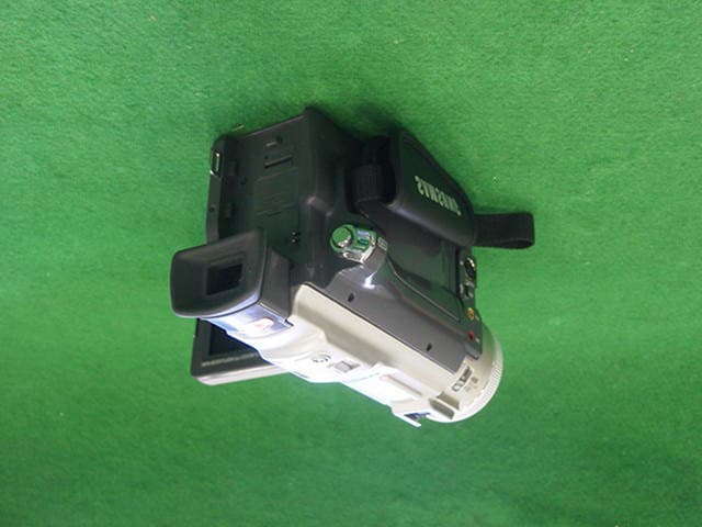
Click to zoom
Application Details
- Equipment Class
- JBP - Part 15 Class B Computing Device Peripheral
- Date of Grant
- May 13, 2002
- Application Purpose
- Original Equipment
- Date of Application
- May 13, 2002
- Equipment Note
- Digital Camcorder
- Company
- Samsung Electronics Co Ltd
- Country
- United States
Documents & Files
Document Text
Text extracted from the exhibit documents filed with the FCC. Open a document above to read the original.
Users Manual
ENGLISH ELECTRONICS *Samsung Electronics’ Internet Home Pagehttp://www.samsungusa.com AD68-00516B THIS CAMCORDER IS MANUFACTURED BY: SAMSUNG Electronics America Inc. 105 Challenger Road, Ridgefield Park N.J 07660-0511 Tel: 1-800-SAMSUNG (1-800-726-7864) 00516B SCD86/D87-SEA (01~27) 3/29/02 3:00 PM Page 100 ENGLISH START/ STOP SELF TIMER A.DUB ZERO MEMORY PHOTO DISPLAY X2 SLOW F.ADV PHOTO SEARCH DATE/ TIME Digital Video CamcorderOwner’s Instruction BookBefore operating the unit, please read thisinstruction book thoroughly, and retain it forfuture reference. AF Auto Focus CCD Charge Coupled Device LCD Liquid Crystal Display SCD86/D87 ELECTRONICS US PATENT 4415844 00516B SCD86/D87-SEA (01~27) 3/29/02 3:00 PM Page 101 ENGLISH Notices and Safety Instructions Safety Instructions RISK OF ELECTRIC SHOCK DO NOT OPEN CAUTION: TO REDUCE THE RISK OF ELECTRIC SHOCK, DO NOTREMOVE COVER(OR BACK). NO USER SERVICEABLEPARTS INSIDE, REFER SERVICING TO QUALIFIEDSERVICE PERSONNEL. This symbol is intended to alert the user to the presence of uninsulateddangerous voltage within the product’s enclosure that may be ofsufficient magnitude to constitute a risk of fire or electric shock. This symbol is intended to alert the user to the presence of importantoperating and maintenance instructions in the literature accompanyingthis product. To prevent electric shock, match wide blade of plugto wide slot and fully insert.1. READ INSTRUCTIONS: All the safety and operating instructions should be read before the CAMCORDER is operated. 2. RETAIN INSTRUCTIONS: The safety and operating instructions should be retained for future reference. 3. HEED WARNINGS: All warnings on the CAMCORDER and in the operatinginstructions should be adhered to. 4. FOLLOW INSTRUCTIONS: All operating and maintenance instructions should be followed. 5. CLEANING: Unplug this CAMCORDER from the wall outlet before cleaning. Do not use liquid or aerosol cleaners. Use a dry cloth used for dusting cabinets. 6. ATTACHMENTS: Do not use attachments not recommended by the CAMCORDER product manufacturer as they may be hazardous. 7. WATER AND MOISTURE: Do not use this CAMCORDER near water; for example, near a bathtub, wash bowl, kitchen sink, laundry tub, in a wet basement, near a swimming pool or lake. 8. ACCESSORIES: Do not place this CAMCORDER on an unstable cart, stand, tripod,bracket or table. The CAMCORDER may fall, causing serious injuryto a child or adult, and serious damage to the unit. Use only with a cart, stand, tripod, bracket, or table recommendedby the manufacturer or sold with the CAMCORDER. Any mountingof the unit should follow the manufacturer’s instructions and shoulduse a mounting accessory recommended by the manufacturer.A. An appliance and cart combination should be moved with care. Quick stops, excessive force and uneven surfaces may cause the appliance and cart combination to overturn. PORTABLE CART WARNING(Symbol provided by RETAC) CAUTION ENGLISH Notices and Safety Instructions9. VENTILATION: Slots and openings in the cabinet are provided for ventilation to ensure reliable operation of the CAMCORDER and to protect it from overheating. These openings must not be blocked or covered. Never place your CAMCORDER on a bed, sofa, rug, or other similar surface: on or near a radiator or heat register. This CAMCORDER should not be placed in a built-in installation such as a bookcase or rack unless proper ventilation is providedor the manufacturer’s instructions have been adhered to. 10. POWER SOURCES: The CAMCORDER should be operated only from the type of power source indicated on the label.If you are not sure of the type of power supply at your home, consult your appliance dealer or local power company. A CAMCORDER is intended to be operated from battery power, or other sources, refer to the operating instructions. 11. GROUNDING OR POLARIZATION: This CAMCORDER may be equipped with either a polarized 2-wire AC line plug (a plug having one blade wider than the other)or a 3-wire grounding type plug, a plug having a third (grounding)pin.If you are unable to insert the plug fully into the outlet, try reversingthe plug. If the plug still fails to fit, contact your electrician to replace your outlet. Do not defeat the safety purpose of the polarized plug. 12. POWER-CORD PROTECTION: Power-supply cords should be routed so that they are not likely tobe walked on or pinched by items placed upon or against them, paying particular attention to cords or plugs, convenient receptacles, and the point where they exit from the unit. 13. OUTDOOR ANTENNA GROUNDING: If an outside antenna or cable system is connected to the CAMCORDER, be sure the antenna or cable system is groundedto provide some protection against voltage surges and built-up static charges, Section 810 of the National Electrical Code, ANSI/NFPA No. 70-1984, provides information with respect to proper grounding of the mast and supporting structure, groundingof the lead-in wire and supporting structure, grounding of the mastand supporting structure, grounding of the lead-in wire to an antenna discharge unit, size of grounding to conductors, locationof antenna-discharge unit, connection to grounding electrodes and requirements for the grounding electrode.See figure below. GROUNDING CONDUCTORS (NEC SECTION 810-21) GROUND CLAMPS POWER SERVICE GROUNDINGELECTRODE SYSTEM(NEC ART 250, PART H) NEC NATIONAL ELECTRICAL CODE ELECTRICSERVICEEQUIPMENT GROUNDCLAMP ANTENNALEAD INWIRE ANTENNADISCHARGE UNIT(NEC SECTION 810-20) ENGLISH Notices and Safety Instructions14. LIGHTNING: For added protection of this CAMCORDER during a lightning storm o when it is left unattended and unused for long periods of time, unplug it from the wall outlet and disconnect the antenna orcable system. This will prevent damage to the CAMCORDER due to lightning and power-line surges. 15. POWER LINES: An outside antenna system should not be located in the vicinity ofoverhead power lines or other electric light or power circuits whereit can fa…
Text truncated - open the document above for the full version.
Test Report
ERI Electromagnetic research institute 66-6, JEIL-RI, YANGJI-MYUN, YOUNGIN-CITY, KYUNGGI-DO, KOREA TEL: 82 31 336 1186 FAX : 82 31 336 1184 homepage : This test report shall not be reproduced except in full, Without the written approval. ReportNo.:ERI-FCC-0110 Page : 1 of 24 EMI TEST REPORT Test report no. : ERI-FCC-0110 Type of equipment : DIGITAL VIDEO CAMERA Model no. : SCD87 Applicant. : SAMSUNG ELECTRONICS CO., LTD. Test standards : FCC Part15 Subpart B (Class B) Test Procedure and Items : - AC Power line Conducted Emissions Measurement : ANSI C63.4-1992 - Radiated Emissions Measurement : ANSI C63.4-1992 Test result : Complied This equipment has been tested to comply with the requirements of FCC Rules and Regulations Part 15 Subpart B Unintentional Radiators. The results in this report apply only to the sample tested. This test report shall not be reproduced except in full, Without the written approval of ERI Laboratory. Date of test: 2002. 4. 24 .30 Issued date: 2002. 5. 1 Tested by : approved by: GWEON, HUR SANG-KYE, LEE This laboratory is registered by KOLAS, KOREA. This test report have been performed in accordance with Its terms of registration. ERI Electromagnetic research institute 66-6, JEIL-RI, YANGJI-MYUN, YOUNGIN-CITY, KYUNGGI-DO, KOREA TEL: 82 31 336 1186 FAX : 82 31 336 1184 homepage : This test report shall not be reproduced except in full, Without the written approval. ReportNo.:ERI-FCC-0110 Page : 2 of 24 Contents 1. client information 2. Laboratory information 3. TEST SYSTEM CONFIGURATION 3.1 Operation Environment 3.2 Measurement Uncertainty 3.3 sample calculation 4. Description of e.u.t. 4.1 Product Description 4.2 Peripherals 4.3 used cables 4.4 e.u.t. test configuration 4.5 operating conditions 5. Test Results 5.1 Conducted Emission 5.1.1 Measurement procedure 5.1.2 Used equipments 5.1.3 measurement uncertainty 5.1.4 test data(downloading) 5.1.5 test data(rec) 5.1.6 test data(play) 5.1.7 result ERI Electromagnetic research institute 66-6, JEIL-RI, YANGJI-MYUN, YOUNGIN-CITY, KYUNGGI-DO, KOREA TEL: 82 31 336 1186 FAX : 82 31 336 1184 homepage : This test report shall not be reproduced except in full, Without the written approval. ReportNo.:ERI-FCC-0110 Page : 3 of 24 5.2 Radiated Emission 5.2.1 Measurement procedure 5.2.2 Used equipments 5.2.3 measurement uncertainty 5.2.4 test data(downloading) 5.2.5 test data(rec) 5.2.6 test data(play) 5.2.7 result 6. Photographs Conducted Emission test Radiated Emission Test EUT(Front, Rear, Inner) Main Board(Front, Rear) LCD Board(Front, Rear) Memory Board(Front, Rear) ERI Electromagnetic research institute 66-6, JEIL-RI, YANGJI-MYUN, YOUNGIN-CITY, KYUNGGI-DO, KOREA TEL: 82 31 336 1186 FAX : 82 31 336 1184 homepage : This test report shall not be reproduced except in full, Without the written approval. ReportNo.:ERI-FCC-0110 Page : 4 of 24 1. Client information Applicant : SAMSUNG ELECTRONIC CO., LTD Address : 416, Maetan-3dong, Paldal-Gu, Suwon-City, Kyungki- Do, Korea Telephone Number : 81-31-200-5754 Facsimile Number : 81-31-200-3458 Contact person : Kang jae soon Manufacturer : SAMSUNG ELECTRONIC CO., LTD Address : 416, Maetan-3dong, Paldal-Gu, Suwon-City, Kyungki-Do, Korea Telephone Number : 81-31-200-5754 Facsimile Number : 81-31-200-3458 2. Laboratory information Address The open area test site and EMC facilities are used for these testing. This facility was accredited by KOLAS, EK of Korea, MIC, FCC. EMC RESEARCH INSTITUTE . 66-6, JEIL-RI, YANGJI-MYUN, YOUNGIN-CITY, KYUNGGI-DO, KOREA Telephone Number : 82- 31- 336- 1186 Facsimile Number : 82- 31- 336 -1184 KOLAS No. : 111 EK : J MIC : KR0030 FCC Filing No. : 302567 ERI Electromagnetic research institute 66-6, JEIL-RI, YANGJI-MYUN, YOUNGIN-CITY, KYUNGGI-DO, KOREA TEL: 82 31 336 1186 FAX : 82 31 336 1184 homepage : This test report shall not be reproduced except in full, Without the written approval. ReportNo.:ERI-FCC-0110 Page : 5 of 24 MAP IC(), TG , 17 (42 ) FA TG TG 3km (ERI) ERI Electromagnetic research institute 66-6, JEIL-RI, YANGJI-MYUN, YOUNGIN-CITY, KYUNGGI-DO, KOREA TEL: 82 31 336 1186 FAX : 82 31 336 1184 homepage : This test report shall not be reproduced except in full, Without the written approval. ReportNo.:ERI-FCC-0110 Page : 6 of 24 3. TEST SYSTEM CONFIGURATION 3.1 Operation Environment Temperature Humidity Pressure 3m OATS : 13.5C 36 % 1001hPa Shielded room : 22.0C 39 % 998hPa 3.2 Measurement Uncertainty All measurements involve certain levels of uncertainties, specially in field of EMC. The factors contributing to uncertainties are test receiver, Cable loss, antenna factor calibration, Antenna directivity, antenna factor variation with height, antenna phase center variation, antenna Frequency interpolation, measurement distance variation, site imperfection, mismatch, and system repeatability. Based on NIS 80,81, The measurement uncertainty level with a 95% confidence level were applied. ERI Electromagnetic research institute 66-6, JEIL-RI, YANGJI-MYUN, YOUNGIN-CITY, KYUNGGI-DO, KOREA TEL: 82 31 336 1186 FAX : 82 31 336 1184 homepage : This test report shall not be reproduced except in full, Without the written approval. ReportNo.:ERI-FCC-0110 Page : 7 of 24 3.3 sample calculation Conducted emission The field strength is calculated by adding the LISN factor, cable loss from the measured reading. The sample calculation is as follows : FS = MR + LF + CL MR = Meter Reading LF = LISN Factor CL = Cable Loss If MR is 30dB, LISN Factor 1dB, CL 1dB The result (MR) is 30 + 1 + 1 = 32dBuV radiated emission The field strength is calculated by adding the antenna Factor, cable loss and, Antenna pad subtracting the amplifier gain from the measured reading. The sample calculation is as follows : FS = MR + AF + CL + AT -AG MR = Meter Reading AF = Antenna Factor CL = Cable Loss AT = Antenna Pad AG=Amplifier Gain If MR is 30dB, AF 12dB, CL 5dB, AP 10dB, AG 35dB The result (MR) is 30 + 12 + 5 + 10 –35 = 22dBuV/m ERI Electromagnetic research institute 66-6, JEIL-RI, YANGJI…
Text truncated - open the document above for the full version.
Contact Information
Applicant
Jenni Chun(General Manager)
Test Firm
EMC Research InstituteKyu-Hong Jung
Technical Specifications
| # | Rule Parts | Frequency Range | Power Output |
|---|---|---|---|
| 1 | 15B | - | - |
Other Applications from Samsung Electronics Co Ltd
A3LSMS741B
Aug 05, 2026Portable Handset
Equipment Class
6VL - 15E 6 GHZ Very Low Power DeviceA3LSMX940
Jul 31, 2026BT,BLE Tablet DTS,UNII a,b,g,n,ac,ax,be and digitizer
Equipment Class
DTS - Digital Transmission SystemA3LSMS741U
Jul 30, 2026Portable Handset
Equipment Class
6CD - 15E 6 GHz Low Power Dual ClientA3LSMX840
Jul 27, 2026BT,BLE Tablet DTS,UNII a,b,g,n,ac,ax and Digitizer
Equipment Class
DSS - Part 15 Spread Spectrum TransmitterA3LSMX848U
Jul 27, 2026WCDMA, LTE, 5G NR Tablet BT,BLE, DTS,UNII a b g n ac ax and Digitizer
Equipment Class
JBP - Part 15 Class B Computing Device Peripheral