A3LSP30Notebook PC
Samsung Electronics Co Ltd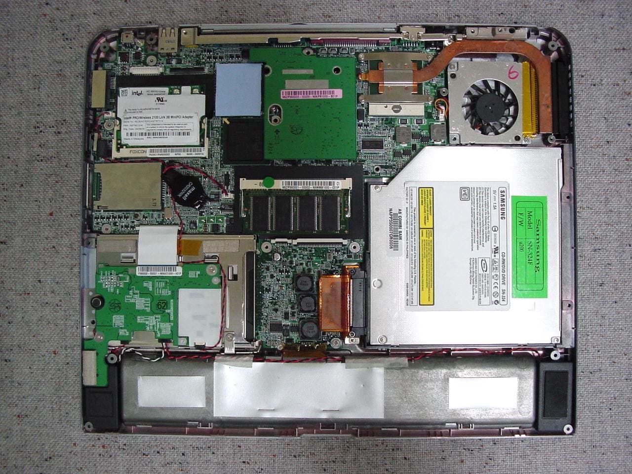
Click to zoom
Application Details
- Equipment Class
- JBC - Part 15 Class B Computing Device/Personal Computer
- Date of Grant
- Nov 13, 2003
- Application Purpose
- Original Equipment
- Date of Application
- Nov 13, 2003
- Equipment Note
- Notebook PC
- Company
- Samsung Electronics Co Ltd
- Country
- United States
Documents & Files
Document Text
Text extracted from the exhibit documents filed with the FCC. Open a document above to read the original.
Users Manual
Connecting to the Internet 35 Connecting Through a Wired LAN 1.Connect a LAN cable to the computer’s LAN port. 2.Click Start > Control Panel. 3.Click Network and Internet Connections in the [Control Panel] window. 4.Click Network Connections in the [Network and Internet Connections] window. 5.Right-click the Local Area Connection icon and click Properties. 36 Users Manual 6.On the General tab, select “Internet Protocol(TCP/IP)” and click Properties. 7. To use DHCP: On the General tab, select “Obtain an IP address automatically” and “Obtain DNS server address automatically”. Click OK. To use a static IP: On the General tab, select “Use the following IP address” and fill in the IP address, Subnet mask, Default gateway, Preferred DNS server, and Alternative DNS server fields. Click OK. To use both DHCP and static IP simultaneously: On the Alternate Configuration tab, click User configured and fill in the fields. Click OK. Connecting to the Internet 37 Connecting Through a Wireless LAN (Option) A wireless network (Wireless LAN) environment is a network environment that enables communication between multiple computers at home or a small-size office through wireless LAN devices. Using the wireless network connections between the systems, you can use normal network functions such as sharing of files, folders and printers. Using computer-to- computer network (ad hoc) connections, you can access the Internet through a computer connected directly to the Internet even if your computer is not directly connected to the Internet. For details, see “Using Network Services” on page 48. The information provided in this section only applies to models equipped with an optional wireless LAN device. To turn off the Wireless LAN If the wireless LAN is turned on, the computer consumes much power, therefore shortening the amount of time you can run on battery. Therefore, if you are not using the WLAN or if you are in an environment that does not provided WLAN, you are recommended to turn off the WLAN by pushing the WLAN/Bluetooth button (p15) on the computer. Wireless network connections can be classified into two categories. 1) Access Point You can connect to an AP to use the network. This is possible only in an environment equipped with an AP. For details, see “Connecting to an Access Point (AP)” on page 38. What is an Access Point (AP)? An AP is a network device that bridges wired and wireless LANs, and corresponds to a wireless hub in a wired network. You can connect multiple wireless LAN installed computers to an AP. 2) Computer-to-computer (ad hoc) This is also called a peer-to-peer or ad hoc network. In computer-to-computer wireless networks, you can wirelessly connect 2 or more computers that have wireless LAN modules. Using computer-to-computer wireless 38 Users Manual networks, you can access the Internet through a computer that is connected to the Internet even if your computer is not directly connected to the Internet. For details, see “Connecting to computer-to-computer networks (peer-to-peer or ad hoc)” on page 39. Connecting to an Access Point (AP) This section describes how to connect to an AP. You can use the network when you are connected to an AP. In this section, the configuration procedures are described for Windows XP installed computers. For information on the configuration procedures for other operating systems, see “Using Wireless Networks in Other Operating Systems” on page 44. Please ask your network administrator about detailed configuration information such as the network key (encryption key). 1.Right-click on the Wireless Network Connection () icon on the taskbar, and select View Available Wireless Networks. 2.Select your desired AP (e.g. Test) to connect, and enter the encryption key for the AP in the Network key field, and click Connect. Connecting to the Internet 39 If the network key is not configured for the desired AP, select 'Allow me to connect to the selected wireless network, even though it is not secure’. Now you are connected to the AP, and you can access the network. Checking the connection status Move the mouse pointer over the Wireless Network Connection () icon on the taskbar, and the connection status is displayed. Connecting to computer-to-computer networks (peer-to-peer or ad hoc) In computer-to-computer wireless networks, you can wirelessly connect 2 or more computers that have wireless LAN modules. You can connect by completing the following steps: xStep 1. Set up a computer-to-computer network on a computer. xStep 2. Connect to the configured computer from other computers. In this section, the configuration procedures are described for Windows XP installed computers. For information on the configuration procedures for other operating systems, see “Using Wireless Networks in Other Operating Systems” on page 44. 40 Users Manual Step 1. Setting up a computer-to-computer network 1.Right-click on the Wireless Network Connection () icon on the taskbar, and select View Available Wireless Networks. 2.Click Advanced. 3.On the Wireless Network tab, click Advanced. 4.Clear 'Automatically connect to non-default network' check box, if it is selected. Select 'Computer-to-computer (ad hoc) networks only', and click Close. 5.In the Wireless Networks tab, click Add. Connecting to the Internet 41 6.Enter the network name (e.g. samsung), and unselect 'The key is provided for me automatically'. Enter the encryption key in the Network key field, and click OK. To prevent a network connection from an unauthorized user, it would be better to configure a network key (encryption key). A network key consists of 5 or 13 alphanumeric characters (e.g. magic), or of 10 or 26 hexadecimal numbers (a hexadecimal number is represented by numbers '0' to '9' or letters 'a' to 'f'). 42 Users Manual 7.Check that the configured network name (e.g. samsung) is in the ’Preferred networks’ item, and click OK. Now your wireless network setup has been completed. Step 2. Connecting to the configured compute…
Text truncated - open the document above for the full version.
Users Manual
Customizing Your Computer 63 Using External Display Devices Using external display devices such as a monitor, projector, TV, etc allows you to view screen images alternatively or simultaneously on each device. You can also split a screen into two display devices, or view different images on each display device. Using external display devices is especially useful when you are giving a presentation or watching a movie through your TV. Switching Display Devices Using the Shortcut Key You can watch the screen through either the LCD or an external display device, or you can even watch the screen through both the LCD and an external display device simultaneously. 1.Connect the external display device (e.g. a monitor or a projector) to the corresponding port of the system.To connect a TV, connect the TV to the TV output port of the system. 2.Press the <Fn>+<F4/> keys. Provided that an external display device is connected, the display option changes in LCD > CRT > LCD+CRT order whenever the <Fn>+<F4/> keys are pressed. Provided that multiple external display devices are connected, the display order would be LCD > CRT > LCD+CRT > TV whenever the <Fn+F4/> keys are pressed. You cannot view the screen via the LCD, CRT, and TV simultaneously. Using Dual View to View Extended Screen You can expand the screen into two display devices and work conveniently in separate workspaces. In Dual View mode, you can select the screen resolution and color quality for each display device, as if there were two separate graphics cards. 1.Connect the external display device (e.g. a monitor or a projector) to the corresponding port of the system. To connect a TV, connect the TV to the TV output port of the system. 2.Click Start > Control Panel > Appearance and Themes > Change the screen resolution. 64 Users Manual 3.Click the monitor '2' icon, select the 'Extend my Windows desktop onto this monitor' check box, and then click Apply. 4.When the configuration is complete, click OK on the left side of Troubleshoot. The primary display device(the LCD) is indicated as '1', and the secondary display device is indicated as '2'. Now you can view the screen through two monitors. When using Dual View, it is recommended that LCD is kept as '1', the primary display device. 2 : Secondary1 : Primary Customizing Your Computer 65 If the screen of the secondary display device is displayed at 640x480 pixels, with 256 colors, change the settings to the desired screen resolution and color quality in the [Display Properties] window. Deactivating Dual View Mode Click the monitor '2' icon, clear the 'Extend my Windows desktop onto this monitor' check box, and then click Apply. To move a window between display devices in Dual View mode. Click the title bar of the window in the primary display device(1, the LCD), and drag it to the secondary display device (2). The window is move to the secondary display device. 66 Users Manual System Management Using Power Management Options Your computer includes Power Management options that can help the battery charge last longer and extend the life of the battery. Power-management options will slow down or shut off system components when the components are not being used. Power management may slow down system performance. Your computer runs fastest with the power cord attached, when power management is disabled. In the next sections, basic and advanced methods of power management will be discussed. Basic Power Management Schemes This section discusses the basic schemes of power management when the computer is operating on battery power or using AC power. Standby vs. Hibernation Hibernation is a state where the contents of memory are stored in a special file on the hard disk, and Standby simply keeps a small holding current through the memory to keep the data. You are more likely to sustain loss of data in Standby mode so it is recommended to save all open files before entering Standby. Changing Devices: Do not change PC Cards while in standby or hibernate modes. To enter the power management window complete the following: 1.Click Start > Control Panel > Performance and Maintenance. 2.Click icon to display the Power Options Properties window. System Management 67 3.Click the Power Schemes tab to display the basic power management options. 4.Select the time that you wish each of the following actions to occur in Battery and AC power mode. xTurn off monitor xTurn off hard disks xSystem standby xSystem hibernates Turning off the monitor and HDDs will save a substantial amount of battery power, therefore when in battery only mode select the shortest time practical. aHibernate Mode (Power Management or Manual Method) When hibernation is used, your computer turns off and when you power up again, everything is restored exactly as you left it—including programs and documents you may not have saved or closed. Everything in memory gets saved to the HDD, and the monitor and hard disk get turned off. By default, the power scheme is configured to SAMSUNG mode. SAMSUNG mode extends the battery life and optimizes the Intel Speedstep function.To use SAMSUNG mode after reinstalling Windows, install the PowerCFG program using the system software CD. 68 Users Manual If You Reinstall Windows: You should re-establish hibernate in power options by opening Power Options Properties window and click on the Hibernate tab then click “Enable Hibernation”. Frequent Interruptions: If you experience frequent interruptions, you might also consider putting your computer into automatic hibernation after a specified number of minutes using the power management options. aStandby Mode (Power Management or Manual Method) Standby is used mainly for conserving battery power in your notebook computer. It also gives you the benefit of getting right back to your work without waiting for the computer to restart. Standby turns off your monitor and hard disks, placing your entire system in a low-power state. When you return to your computer, restores y…
Text truncated - open the document above for the full version.
Users Manual
Notices i Notices No part of this publication may be reproduced, stored in a retrieval system, or transmitted, in any form or by any means, mechanical photocopying, recording or otherwise, without the prior written permission of the manufacturer. The information within this manual is subject to change without notice. The manufacturer shall not be held liable for technical or editorial errors or omissions contained in herein; nor for incidental or consequential damages resulting from the furnishing, performance or use of this material. Microsoft Windows is a registered trademark of the Microsoft Corporation. Product names mentioned herein are for identification purposes only, and may be trademarks and/or registered trademarks of their respective companies. Macrovision Statement If your computer has a DVD drive and an analog TV Out port, the following paragraph applies: This product incorporates copyright protection technology that is protected by method claims of certain U.S. patents and other intellectual property rights owned by Macrovision Corporation and other rights owners. Use of this copyright protection technology must be authorized by Macrovision Corporation, and is intended for home and other limited viewing uses only unless otherwise authorized by Macrovision Corporation. Reverse engineering or disassembly is prohibited. Copyright 2002 All rights are reserved Notice and Safety With Wireless - English.fm Page i Saturday, March 30, 2002 2:59 PM ii Users Manual Important Safety Information Safety Instructions Your system is designed and tested to meet the latest standards for safety of information technology equipment. However, to ensure safe use of this product, it is important that the safety instructions marked on the product and in the documentation are followed. Always follow these instructions to help guard against personal injury and damage to your system. i Setting Up your System •Read and follow all instructions marked on the product and in the documentation before you operate your system. Retain all safety and operating instructions for future use. •Do not use this product near water or a heat source such as a radiator. •Set up the system on a stable work surface. •The product should be operated only with the type of power source indicated on the rating label. •Ensure that the electrical outlet you are using to power your equipment is easily accessible in case of fire or short circuit. •If your computer has a voltage selector switch, make sure that the switch is in the proper position for your area. •Openings in the computer case are provided for ventilation. Do not block or cover these openings. Make sure you provide adequate space, at least 6 inches (15 cm), around the system for ventilation when you set up your work area. Never insert objects of any kind into the computer ventilation openings. •Ensure that the fan vents on the bottom of the casing are clear at all times. Do not place the computer on a soft surface, doing so will block the bottom vents. •If you use an extension cord with this system, make sure that the total ampere rating on the products plugged into the extension cord does not exceed the extension cord ampere rating. Notice and Safety With Wireless - English.fm Page ii Saturday, March 30, 2002 2:59 PM Important Safety Information iii Care During Use •Do not walk on the power cord or allow anything to rest on it. •Do not spill anything on the system. The best way to avoid spills is to not eat or drink near your system. •Some products have a replaceable CMOS battery on the system board. There is a danger of explosion if the CMOS battery is replaced incorrectly. Replace the battery with the same or equivalent type recommended by the manufacturer. Dispose of batteries according to the manufacturer’s instructions. If the CMOS battery requires replacement insure that a qualified technician performs the task •When the computer is turned off, a small amount of electrical current still flows through the computer. To avoid electrical shock, always unplug all power cables, remove the battery and modem cables from the wall outlets before cleaning the system. •Unplug the system from the wall outlet and refer servicing to qualified personnel if: – The power cord or plug is damaged. – Liquid has been spilled into the system. – The system does not operate properly when the operating instructions are followed. – The system was dropped or the casing is damaged. – The system performance changes. Replacement Parts and Accessories Use only replacement parts and accessories recommended by manufacturer. To reduce the risk of fire, use only No. 26 AWG or larger telecommunications line cord. Written by: Daryl L. Osden Do not use this product in areas classified as hazardous. Such areas include patient care areas of medical and dental facilities, oxygen rich environments, or industrial areas. Notice and Safety With Wireless - English.fm Page iii Saturday, March 30, 2002 2:59 PM iv Users Manual Battery Disposal Do not put rechargeable batteries or products powered by non-removable rechargeable batteries in the garbage. Contact the Samsung Helpline for information on how to dispose of batteries that you cannot use or recharge any longer. Follow all local regulations when disposing of old batteries. Notice and Safety With Wireless - English.fm Page iv Saturday, March 30, 2002 2:59 PM Regulatory Compliance Statements v Regulatory Compliance Statements Wireless Guidance Low power, Radio LAN type devices (radio frequency (RF) wireless communication devices), operating in the 2.4 GHz Band, may be present (embedded) in your notebook system. The following section is a general overview of considerations while operating a wireless device. Additional limitations, cautions, and concerns for specific countries are listed in the specific country sections (or country group sections). The wireless devices in your system are only qualified for use in the countries identified by the Radio Approv…
Text truncated - open the document above for the full version.
Attestation Statements
Mia Kang From: John SC Lee <[email protected]> To: Gregory Czumak <[email protected]> Cc: PCTEST - Randy Ortanez <[email protected]>; PCTEST - Al Cirwithian <[email protected]>; PCTEST - Mia <[email protected]> Sent: Thursday, November 13, 2003 6:44 PM Attach: Safety-Statement-5-FCC-new-policy.pdf Sub ject: RE: FCC ID: A3LSP30 Page 1 of 2 11/14/03 Hello Gregory, Please see the following information as you requested. 1. The WLAN is already certified by FCC. The FCC ID is PD9WM3B2100. The antenna location is on LCD top(more than 20cm from the human body). 2. Please refer the attached FCC statement. John SC Lee -----Original Message----- From: Gregory Czumak [mailto:[email protected]] Sent: Friday, November 14, 2003 12:20 AM To: [email protected] Cc: PCTEST - Randy Ortanez; PCTEST - Al Cirwithian; PCTEST - Mia Subject: FCC ID: A3LSP30 To: John SC Lee/Samsung From: Gregory Czumak/PCTEST TCB Re: FCC ID: A3LSP30 (Notebook PC) Applicant: Samsung Application Received: 11/04/2003 Correspondence Reference Number: 231113A.A3L Confirmation Number: TC3281 Date of Original Email: 11/13/03 Subject: Request for additional information In regards to your recent TCB application referenced above, we kindly request that you provide the following additional information. 1. There appears to be a WLAN, or other transmitter, embedded in the EUT. Is this the case? If so, what is its FCC ID? Where is the antenna located in the EUT? Does the antenna location provide a minimum of 20cm spacing from all people during normal operation? If there is a transmitter in the EUT, it must receive FCC Certification. 2. The statement required by Section 15.21 of the FCC Rules does not appear in the user's manual for the EUT. Please indicate your intent to include this statement in the manual. Proposed Grant Listings: Notebook PC Part 15B 28: An AC Adapter incorporating a ferrite core at the connector end of its DC line must be provided with every unit sold. CE: This device has shown compliance with the conducted emissions limits in 15.107, 15.207, or 18.307 adopted under FCC 02-157 (ET Docket 98-80). The device may be marketed after July 11, 2005, and is not affected by the 15.37(j) or 18.123 transition provisions The items indicated above must be submitted before processing can continue on the above referenced application. Failure to provide the requested information within 60 days of the original e-mail date may result in application dismissal and forfeiture of the filing fees. If you have any questions, please do not hesitate to contact us. Sincerely, Gregory Czumak Senior Certification Engineer PCTEST Engineering Laboratory, Inc. 6660-B Dobbin Road Columbia, MD 21045 410-290-6652 410-290-6654 (Fax) [email protected] Page 2 of 2 11/14/03
Block Diagram
AA BB CC DD EE 1 1 2 2 3 3 4 4 5 5 8,9,10,11 1,2 HOST BUS 593 uFCBGA SM_BUS AGTL1.3V,100MHZ CLOCK GEN.ICS950810 DDR SDRAM 266/333MHz CORONA: BANIAS/ODEM/ATI-M9 BLOCK_DIAGRAM Banias ODEM ThermalSensor (Max.6657) SW BOARD FUN.KEY PWRBUT. DCIN_JackRTC/INV 478 uFCPGA 4851 2.5V & 1.25V& 1.5VLOAD Switch 4945 BATLOW/SD# 465047 CHARGE VCORE SYSTEMMICCTRLPIC16C54MCH & VCCP &1.8V 44 CRT DDR266/333SODIMM X2+2.5V+1.25V .... DDRCAP/RES CPUCAP/RES 3 .... BATTERY4 X 2 ATI M7/M9 AGP 4X TVOUT Hublink 66MHZ CARDBUS REALTEK 8101 ICH4-M LAN IO VCCA, VCCBVPPA, VPPB CRT USB2.0 HDD_CN KEYBOARDCONTROLLERM3885XHP SWAP BAY MINI PCITYPEII PCI_BUS PC87393 LPC, 33MHz LPT CDROM 2'ndHDD LPT COM TVOUT 3.3V, 33MHz SUPER I/O CARDBUS1 SLOT 3 IN 1CARDREADER PS2 1394SLOT INTERNALKEYBOARD IR USB X2 421 BGA RICOHR5C593 COM IDE_BUS LAN USB X2 DCJACK LINEIN LINEOUT RJ 45 PORT REPLICATER FP BOARD FINGERPOINT 1394SLOT AC97STAC9721 AUDIO BOARD MDC+BT LVDS &INV. FWH MODEM BLOCK DIAGRAM 0.3 Corona CO020SEC.DSN 1 54 Tuesday, June 03, 2003 Julian Kuo PROJECT: SHEET OF DATE: REVISION DESCRIPTION: DESIGN ENGINEER : SCHEMATIC FILE NAME :RELEASE DATE :
ID Label/Location Info
Page 16 of 17 Project NO. : LBE032266 5. FCC Label Configuration and Location 5.1, 5.2 Label and Label Location This report shall not be reproduced except in full, without the written approval of SEC EMC Testing laboratory.
Test Report
Page 1 of 17 Project NO. : LBE032266 Product :Notebook PC Model No. : P 30, T2200 FCC ID : A3LSP30 1. This test reports shall not be reproduced except in full, without the written approval of SEC EMC Testing laboratory. 2. This test reports does not constitute an endorsement by NIST/NVLAP or U.S Government. 3. This test report is to certify that the tested device properly complies with the requirements of FCC Rules and Regulations Part 15 Subpart B Unintentional Radiators. All tests necessary to show compliance to the requirements were and these results met the specifications requirement. 4. That data in this report are traceable to National or International Standards. Date of test : Oct 31, 2003 Issued Date : Nov 3, 2003 Tested by: Kyeong Dong, KIM / Test Engineer Reviewed by: No Cheon, PARK / Manager of EMC Lab. Authorized by: Kyu Baek, CHUNG / Chief of EMC Lab. This laboratory is registered by the NIST/NVLAP, U.S.A. The test reported herein have been performed in accordance with its terms of registration. EMI TEST REPORT According to FCC Part 15 Subpart B/Class B NVLAP Code: 200623- Page 2 of 17 Project NO. : LBE032266 Table of Contents 1. General Information 1.1 Product Description 1.2 Configuration of EUT and peripherals 1.3 Used Cable Description 1.4 System Block Diagram of Test Configuration 1.5 Test Facility 2. System Test Configuration 2.1 Configuration of Radiated and Conducted Interference Measurement 2.2 Operation Environment 2.3 Test Procedure 2.4 Measurement Uncertainty 3. Conducted Emission Test Data 4. Radiated Emission Test Data 5. Label Configuration and Location 6. Test Equipment Used Distribution This test report has been made available as follows: CS Management Center, EMC Laboratory1 original Computer Division1 copy This report shall not be reproduced except in full, without the written approval of SEC EMC Testing laboratory. Page 3 of 17 Project NO. : LBE032266 1. General Information Applicant :Samsung Electronics Co., Ltd. Full Address :416 Maetan 3 Dong, Paldal-Ku, Suwon City, Kyungki Do, Korea, 442-742 Kind of Product :Notebook PC FCC ID:A3LSP30 Project Name :Corona Model & Variant Names : P30 (Brand Name: Samsung) T2200(Brand Name: Micronpc) Manufacturer :Samsung Electronics Co., Ltd. Test Report Produced by :Kyeong Dong, KIM / Test Engineer This report shall not be reproduced except in full, without the written approval of SEC EMC Testing laboratory. Page 4 of 17 Project NO. : LBE032266 1.1 Product Description 1) Justification The system was configured for testing in typical fashion use. Cable were attached to each of the available I/O Ports. Where applicable, peripherals were attached to the I/O cables. The mode of operation utilized for testing was selected to best simulate typical EUT use. The system was tested using the below configurations of (A), (B), (C), (D), (E), and (F). (A) CPU 1600MHz, ODEM-333, ATI M9-CSP64, AUO LCD 15.0" SXGA+ (B) CPU 1700MHz, ODEM-333, ATI M9-CSP64, AUO LCD 15.0" XGA (C) CPU 1400MHz, ODEM-266, ATI M9+32CL, AUO LCD 14.1" XGA (D) CPU 1500MHz, ODEM-266, ATI M9-CSP64, SEC LCD 15.0" XGA (E) CPU 1700MHz, ODEM-333, ATI M9-CSP64, SEC LCD 15.0" SXGA+ (F) CPU 1500MHz, ODEM-266, ATI M9+32CL, SEC LCD 14.1" XGA This report is for above (E) configuration with the worst case component. So the data of the maximum EUT operation was reported. Further details of cabling and configuration are shown in the test syste m This report shall not be reproduced except in full, without the written approval of SEC EMC Testing laboratory. Page 5 of 17 Project NO. : LBE032266 2) Operating Frequency : 1700MHz for CPU speed, 100MHz for CPU clock, 66MHz for the MCH, 33MHz for all PCI clocks, 27MHz for ATI Video, 66 MHz for ICH4-M, 32.768 kHz XTAL for ICH4-M real time clock, 14.318MHz for Clock Generator, 24.576MHz XTAL for SIGMATEL_9750TLC5 Audio Codec, 24.576MHz XTAL for R5C593 1394/PCMCIA/Memory stick Controller, 25MHz XTAL for LF8423 LAN Controller, 8MHz XTAL for MICOM 3) Description of Testing operating mode The EUT exercise program used during radiated and conducted emissions testing was the Samsung Standardized Emission Test Program for Windows. During the certification test, the LCD panel was open and video signals were simultaneously active on the LCD panel, the S-video output port, and the VGA port simultaneouly. All external peripherals were connected to the I/O ports on the advanced port replicator unless specified below. The system was configured for testing in a typical fashion that a customer would normally use, and was tested while in an automated non-attendant mode. The program repetitively sends a screen of H's to the display, reads and writes to the hard drive, and writes to all serial , parallel ports and modem. Music is played from the CD player to the Line-In jack and ported out to the headphones. As the keyboard, microphone, and mouse are strictly input devices, no data was transmitted to them during the performance of the emissions testing. They were however, continuously scanned for data input activity. A hard drive from the remote PC was mapped to the EUT and a data file was read and written over the network connection to provide continuous activity. The EUT was connected to a remote Final testing was performed at 100 Mbps operation. 4) Tested Resolution : This section provides details of the equipment under test (EUT) and the peripheral assemblies attached during radiated ,conducted emissions and immunity testing. For the 15.0” panel the SXGA+ resolution was set to its maximum value of 1400 x 1050. and VGA Monitor was set to the resolution of 1280 x 1024. This report shall not be reproduced except in full, without the written approval of SEC EMC Testing laboratory. Page 6 of 17 Project NO. : LBE032266 5) Assemble Parts ItemSpecificationRemark CPUIntel Banias CPU 1700MHz 479pin uFCBGA 400 MHz system bus On-die 1MB L2 cache Main Memory512MB DDR type Chip set and ODEM-333, VideoATI M9-CSP64, Integrated Graphic memory 64MB Flat Panel SEC, LC…
Text truncated - open the document above for the full version.
Test Setup Photos
Page 10 of 17 Project NO. : LBE032266 2. System Test Configuration 2.1 Configuration of Radiated and Conducted Interference Measurement * Cabling was taken into consideration and test data was taken under worse case conditions. 1)Conduction(Front View) 2)Conduction(Rear View) This report shall not be reproduced except in full, without the written approval of SEC EMC Testing laboratory. Page 11 of 17 Project NO. : LBE032266 3) Radiation(Front View) 4) Radiation(Rear View) This report shall not be reproduced except in full, without the written approval of SEC EMC Testing laboratory.
Contact Information
Applicant
Jenni Chun(General Manager)
Technical Contact
PCTEST Engineering Lab., Inc.Randy Ortanez
410-290-6652
6660-B Dobbin Road · Columbia, Maryland · United States
Test Firm
SAMSUNG ELECTRONICS CO., LTD.No Cheon Park
Technical Specifications
| # | Rule Parts | Frequency Range | Power Output |
|---|---|---|---|
| 1 | 15B | - | - |
Other Applications from Samsung Electronics Co Ltd
A3LSMS741B
Aug 05, 2026Portable Handset
Equipment Class
6VL - 15E 6 GHZ Very Low Power DeviceA3LSMX940
Jul 31, 2026BT,BLE Tablet DTS,UNII a,b,g,n,ac,ax,be and digitizer
Equipment Class
DTS - Digital Transmission SystemA3LSMS741U
Jul 30, 2026Portable Handset
Equipment Class
6CD - 15E 6 GHz Low Power Dual ClientA3LSMX840
Jul 27, 2026BT,BLE Tablet DTS,UNII a,b,g,n,ac,ax and Digitizer
Equipment Class
DSS - Part 15 Spread Spectrum TransmitterA3LSMX848U
Jul 27, 2026WCDMA, LTE, 5G NR Tablet BT,BLE, DTS,UNII a b g n ac ax and Digitizer
Equipment Class
JBP - Part 15 Class B Computing Device Peripheral