A3LSPH700Projector
Samsung Electronics Co Ltd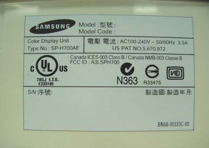
Click to zoom
Application Details
- Equipment Class
- JBP - Part 15 Class B Computing Device Peripheral
- Date of Grant
- Aug 13, 2003
- Application Purpose
- Original Equipment
- Date of Application
- Aug 13, 2003
- Equipment Note
- Projector
- Company
- Samsung Electronics Co Ltd
- Country
- United States
Documents & Files
Document Text
Text extracted from the exhibit documents filed with the FCC. Open a document above to read the original.
Users Manual
..................................................................................................................................... ............. Warning! Important Safety Instructions CAUTION: TO REDUCE THE RISK OF ELECTRIC SHOCK, DO NOT REMOVE COVER (OR BACK). NO USER SERVICEABLE PARTS INSIDE. REFER SERVICING TO QUALIFIED SERVICE PERSONNEL. This symbol indicates high voltage is present inside. It is dangerous to make any kind of contact with any inside part of this product. This symbol alerts you that important literature concerning operation and maintenance has been included with this product. Note to CATV system installer:This reminder is provided to call CATV system installer’s attention to Article 820-40 of the National Electrical Code (Section 54 of Canadian Electrical Code, Part I), that provides guidelines for proper grounding and, in particular, specifies that the cable ground shall be connected to the grounding system of the building as close to the point of cable entry as practical. Caution: FCC/CSA regulations state that any unauthorized changes or modifica- tions to this equipment may void the user’s authority to operate it. Caution: To prevent electric shock, match the wide blade of plug to the wide slot, and fully insert the plug. Attention: pour eviter les chocs electriques, introduire la lame le plus large de la fiche dans la borne correspondante de la prise et pousser jusqu’au fond. Important: One Federal Court has held that unauthorized recording of copyrighted TV programs is an infringement of U.S. copyright laws. Certain Canadian programs may also be copyrighted and any unauthorized recording in whole or in part may be in violation of these rights. To prevent damage which may result in fire or electric shock hazard, do not expose this appliance to rain or moisture. CAUTION RISK OF ELECTRIC SHOCK DO NOT OPEN 2 Thank You for Choosing Samsung Thank you for choosing Samsung! Your new Samsung TV represents the latest in television technology. We designed it with easy-to-use on-screen menus and closed captioning capabili- ties, making it one of the best products in its class. We are proud to offer you a product that will provide convenient, dependable service and enjoyment for years to come. Important Safety Information Always be careful when using your TV receiver. To reduce the risk of fire, electrical shock, and other injuries, keep these safety precautions in mind when installing, using, and maintaining your machine. • Read all safety and operating instructions before operating your TV. • Keep the safety and operating instructions for future reference. • Heed all warnings on the TV receiver and in the operating instructions. • Follow all operating and use instructions. • Unplug the TV receiver from the wall outlet before cleaning. Use a damp cloth; do not use liquid or aerosol cleaners. • Never add any attachments and/or equipment without approval of the manufacturer. Such additions can increase the risk of fire, electric shock, or other personal injury. • Do not use the TV receiver where contact with or immersion in water is a possibility, such as near bath tubs, sinks, washing machines, swimming pools, etc. • Do not place the TV on an unstable cart, stand, tripod, bracket, or table where it can fall. A falling TV can cause serious injury to a child or adult, and serious damage to the appliance. Use only with a cart, stand, tripod, bracket, or table recommended by the manu- facturer or sold with the TV. Follow the manufacturer’s instruc- tions when mounting the unit, and use a mounting accessory rec- ommended by the manufacturer. Move the TV and cart with care. Quick stops, excessive force, and uneven surfaces can make the unit and cart unsteady and likely to overturn. • Provide ventilation for the TV receiver. The unit is designed with slots in the cabinet for ven- tilation to protect it from overheating. Do not block these openings with any object, and do not place the TV receiver on a bed, sofa, rug, or other similar surface. Do not place it near a radiator or heat register. If you place the TV receiver on a rack or bookcase, ensure that there is adequate ventilation and that you’ve followed the manufacturer’s instructions for mount- ing. • Operate your TV receiver only from the type of power source indicated on the marking label. If you are not sure of the type of power supplied to your home, consult your appliance dealer or local power company. • Use only a grounded or polarized outlet. For your safety, this TV is equipped with a polarized alternating current line plug having one blade wider than the other. This plug will fit into the power outlet only one way. If you are unable to insert the plug fully into the outlet, try reversing the plug. If the plug still does not fit, contact your electrician to replace your outlet. 3 4 • Protect the power cord. Power supply cords should be routed so that they won’t be walked on or pinched by objects placed on or against them. Pay particular attention to cords at plugs, convenience receptacles, and the point where they exit from the unit. • Unplug the TV from the wall outlet and disconnect the antenna or cable system during a lightning storm or when left unattended and unused for long periods of time. This will pre- vent damage to the unit due to lightning and power-line surges. • Avoid overhead power lines. An outside antenna system should not be placed in the vicinity of overhead power lines or other electric light or power circuits or where it can fall into such power lines or circuits. When installing an outside antenna system, be extremely careful to keep from touching the power lines or circuits. Contact with such lines can be fatal. • Do not overload the wall outlet or extension cords. Overloading can result in fire or electric shock. • Do not insert anything through the openings in the unit, where they can touch dangerous voltage points or damage parts. Never spill liquid of any kind on the TV. • Ground outdoor …
Text truncated - open the document above for the full version.
Cover Letter(s)
November 13, 2003 Federal Communications Commission Equipment Approval Services 7435 Oakland Mills Road Columbia, MD 21046 Attn: Mr. Mike Nicolay SUBJECT: Samsung Electronics Co., Ltd. FCC ID: A3LSPH700 731 Confirmation No.: TC224866 Correspondence Reference No.: 9668 Request for Tech. Info.: 10/21/03 Dear Mike: Submitted herewith, on behalf of Samsung Electronics Co., Ltd. is an amendment provided in response to the request for technical information dated October 21, 2003. Per our conversation on the telephone yesterday, the EUT (projector) can be classified as a computer monitor for the following reasons. The EUT is a projector with selectable inputs. The user may choose between S-Video In, Composite Video In, DVI In, or the PC VGA input. Most computers in the marketplace have only one video port, so while using the projector on most PC’s, there will be no other video port to connect a monitor. In this configuration the PC display is the projectors output to the user’s wall or screen. Therefore, the projector functions as a computer monitor subject to certification or DoC. Samsung feels that the latest test report for FCC ID: A3LSPH700 uploaded 10/20/2003 complies with the basic configuration requirements of the Commission, and there is no need to add another monitor to the test setup. Samsung respectfully requests that the Commission accepts this test configuration setup for the EUT functioning as a computer monitor. We trust this information is sufficient to resolve FCC questions in this application. If you have any further questions, please do not hesitate to contact us. cc: Samsung Electronics Co., Ltd.
Cover Letter(s)
November 19, 2003 Federal Communications Commission Equipment Approval Services 7435 Oakland Mills Road Columbia, MD 21046 Attn: Mr. Mike Nicolay SUBJECT: Samsung Electronics Co., Ltd. FCC ID: A3LSPH700 731 Confirmation No.: TC224866 Correspondence Reference No.: 10286 Request for Tech. Info.: 11/19/03 Dear Mike: Transmitted herewith, on behalf of Samsung Electronics Co., Ltd. is an amendment provided in response to the request for technical information dated November 19, 2003. 1. Please find attached the test setup photos of the EUT connected to a real world PC. Also attached is the support equipment page. We trust this information is sufficient to resolve FCC questions in this application. If you have any further questions, please do not hesitate to contact us. cc: Samsung Electronics Co., Ltd.
ID Label/Location Info
EUT Photographs [Label and Label position]
Test Report
Project No. : LBE031380 Page 1 of 11 Project No. :LBE031380 Product :PROJECTOR Model No. : SP-H700AE Date of test :June. 25 ~ 27, 2003 Issued Date :July. 3, 2003 Tested by: Jay Yong, PARK / Test Engineer Reviewed by: No Cheon, PARK / Manager of EMC Lab. Authorized by: Kyu Baek, CHUNG / Chief of EMC Lab. SAMSUNG ELECTRONICS Co., Ltd. EMC Test Laboratory 416 Maetan-3 Dong, Paldal-Ku, Suwon City, Kyungki-Do, Korea,442-742 Tel. : 81-31-200-2185 Fax. : 81-31-200-2189 This reports shall not be reproduced except in full, without the written approval of SEC EMC Testing laboratory. EMC TEST REPORT Project No. : LBE031380 Page 2 of 11 Table of Contents 1. Introduction & Summary 1.1 Description of the EUT 1.2 Test facility 1.3 Test equipment 2. Test Set-up 2.1 Test mode 2.2 Justification 2.3 Test equipment setup 2.4 Tested System Details 2.5 System Block Diagram of Test Configuration 2.6 Test rule and Procedure 2.7 Test Summary 3. Test Results 3.1 AC POWERLINE CONDUCTED EMISSION MEASUREMENT 3.2 RADIATED EMISSION MEASUREMENT This reports shall not be reproduced except in full, without the written approval of SEC EMC Testing laboratory. Project No. : LBE031380 Page 3 of 11 1. Introduction & Summary 1.1 Description of the EUT Applicant Project Number Equipment Under Test Trade Name Model Number Variant Model FCC ID Number 1.2 Test facility The EMI/EMS measurement facilities used to collect the tested data are located at 416 Maetan 3 Dong, Paldal-Ku, Suwon City, Kyungki Do, Korea. The sites are constructed in conformance with the requirements of ANSI C63.4 and CISPR 16-1 & 16-2. SAMSUNG Electronics Co.,Ltd is accredited by Korea Laboratory Accreditation Scheme(KOLAS) which signed the International Laboratory Accreditation Cooperation (ILAC) Mutual Recognition Arrangement (MRA) for the above test item(s) and test method(s). Measured in Semi-anechoic chamber #1 that is FCC Registration Number 98856. This reports shall not be reproduced except in full, without the written approval of SEC EMC Testing laboratory. SAMSUNG ELECTRONICS Co., Ltd. LBE031380 PROJECTOR A3LSPH700 - SP-H700AE SAMSUNG Project No. : LBE031380 Page 4 of 11 1.3 Test equipment EquipmentModel No.Serial No.Makers Last calibration and Interval E7405AMY42000109Agilent03/04/18, 12Months Firmware versions : Rev.29.9.86 Quasi-peak adapter85650A2521A00687H.P02/10/09, 12Months 10dB Attenuator8491B58226Agilent37537 RF Relais MatrixPSU861206/024R & SN/A Measurement SoftwareEP5CE-TOYON/A RF SelectorNS49000303-015TOYON/A Measurement SoftwareEP5RE-TOYON/A ESCS30839809/022R & S02/06/27, 12Months Firmware versions : Main 1.08, OTP 02.01, GRA 02.03 Field strength meterESCS30100104R & S03/01/17, 12Months L.I.S.NESH3-Z5847265/028R & S02/10/09, 12Months Bi-Log AntennaCBL6112B2766SCHAFFNER03/06/20, 12Months EMC AnalyzerE7405AUS41110272Agilent03-06-14 This reports shall not be reproduced except in full, without the written approval of SEC EMC Testing laboratory. Spectrum analyzer Field strength meter Project No. : LBE031380 Page 5 of 11 2. Test Set-up 2.1 Test mode The EUT was tested in the following operating modes for the tests mention in this report: Description of Testing operating mode & Tested Resolution Measured each about 2 input(PC VIDEO INPUT mode & Digital Video Interface)of EUT. Further details of cabling and configuration are shown in the test system configuration. The EUT exercise program used during radiated and conducted testing was designed to exercise the various system components in a manner similar to typical use. 2.2 Justification The system was configured for testing in typical fashion use. Cable were attached to each of the available I/O Ports. The mode of operation utilized for testing was selected to best simulate typical EUT use. 2.3 Test equipment setup The explanation of measuring equipment setup when respective function is used in any frequency band is as following: DetectorResolutionVideo functionBandwidthBandwidth Quasi-Peak9kHz- Peak100kHz1MHz Quasi-Peak120kHz- Peak1MHz1MHz This reports shall not be reproduced except in full, without the written approval of SEC EMC Testing laboratory. EMI Test receiverAbove 1000 0.15 to 30EMI Test receiver Spectrum analyzer EMI Test receiver 30 to 1000 1280x720- Frequency Band [MHz] Equipment Horizontal F.: 70kHz Vertical F. : 85Hz - Operating ModeResolutionsRefresh ratesColors Project No. : LBE031380 Page 6 of 11 2.4 Tested System Details 1) Configuration of EUT and peripherals MarkItemModel No.Serial No.ManufacturerFCC ID A PROJECTOR SP-H700AE - Samsung A3LSPH700 BPersonal ComputerM6200450092DN101415Samsung CPS/2 KeyboardSEM-A17R04MB-0000229Samsung DPS/2 MouseM-U48aLZE12153242Logitech * DOC : FCC Declaration of Conformity 2) Used Cable Description No.ItemLength[m]Shielded(Y/N) 1PS/2 Mouse Cable1.8N 2PS/2 Keyboard Cable1.6N 3Video Cable1.5Y 4AC Power Cable(Projector)1.2N 5AC Power Cable(PC)1.8N This reports shall not be reproduced except in full, without the written approval of SEC EMC Testing laboratory. Remark Project No. : LBE031380 Page 7 of 11 2.5 System Block Diagram of Test Configuration 2.6 Test rule and Procedure FCC Rule Part 15, Subpart B : Unintentional Radiators Test Procedure : ANSI C63.4-1992 2.7 Test Summary Result Pass Pass * N/A : Test not applicable This reports shall not be reproduced except in full, without the written approval of SEC EMC Testing laboratory. RADIATED EMISSIONANSI C63.4-1992 Test itemTest Procedure AC POWERLINE CONDUCTED EMISSION ANSI C63.4-1992 4 B A E D 1 2 3 5 POWER POWER Project No. : LBE031380 Page 8 of 11 3. Test Results 3.1 AC POWERLINE CONDUCTED EMISSION MEASUREMENT 3.1.1 Test Procedure Configurate the EUT System in accordance with ANSI C63.4-1992 section 7 and 12.2. Connect the EUT's AC line cord to the EUT port of LISN. All input terminals are terminated in the proper impedance. The output ports are connected to the cable provided with the device and the ending port are terminated in the proper impedance. Using a calibrated coaxial cable, the TEST…
Text truncated - open the document above for the full version.
Test Report
Project No. : LBE031963 Page 1 of 11 Project No. : LBE031963 Product :PROJECTOR Model No. :SP-H700AE Date of test :Sep 5 ~ Sep 6, 2003 Issued Date :Sep 8, 2003 Tested by: Jay Yong, PARK / Test Engineer Reviewed by: No Cheon, PARK / Manager of EMC Lab. Authorized by: Kyu Baek, CHUNG / Chief of EMC Lab. SAMSUNG ELECTRONICS Co., Ltd. EMC Test Laborator y 416 Maetan-3 Dong, Paldal-Ku, Suwon City, Kyungki-Do, Korea,442-742 Tel. : 81-31-200-2185 Fax. : 81-31-200-2189 This reports shall not be reproduced except in full, without the written approval of SEC EMC Testing laboratory. EMC TEST REPORT Project No. : LBE031963 Page 2 of 11 Table of Contents 1. Introduction & Summary 1.1 Description of the EUT 1.2 Test facility 1.3 Test equipment 2. Test Set-up 2.1 Test mode 2.2 Justification 2.3 Test equipment setup 2.4 Tested System Details 2.5 System Block Diagram of Test Configuration 2.6 Test rule and Procedure 2.7 Test Summary 3. Test Results 3.1 AC POWERLINE CONDUCTED EMISSION MEASUREMENT 3.2 RADIATED EMISSION MEASUREMENT This reports shall not be reproduced except in full, without the written approval of SEC EMC Testing laboratory. Project No. : LBE031963 Page 3 of 11 1. Introduction & Summary 1.1 Description of the EUT Applicant Project Number Equipment Under Test Trade Name Model Number Variant Model FCC ID Number 1.2 Test facility The EMI/EMS measurement facilities used to collect the tested data are located at 416 Maetan 3 Dong, Paldal-Ku, Suwon City, Kyungki Do, Korea. The sites are constructed in conformance with the requirements of ANSI C63.4 and CISPR 16-1 & 16-2. SAMSUNG Electronics Co.,Ltd is accredited by Korea Laboratory Accreditation Scheme(KOLAS) which signed the International Laboratory Accreditation Cooperation (ILAC) Mutual Recognition Arrangement (MRA) for the above test item(s) and test method(s). Measured in Semi-anechoic chamber #1 that is FCC Registration Number 98856. This reports shall not be reproduced except in full, without the written approval of SEC EMC Testing laboratory. SAMSUNG ELECTRONICS Co., Ltd. LBE031963 PROJECTOR A3LSPH700 - SP-H700AE SAMSUNG Project No. : LBE031963 Page 4 of 11 1.3 Test equipment EquipmentModel No.Serial No.Makers Last calibration and Interval E7405AMY42000109Agilent03/04/18, 12Months Firmware versions : Rev.29.9.86 Quasi-peak adapter85650A2521A00687H.P02/10/09, 12Months 10dB Attenuator8491B58226Agilent37537 RF Relais MatrixPSU861206/024R & SN/A Measurement SoftwareEP5CE-TOYON/A RF SelectorNS49000303-015TOYON/A Measurement SoftwareEP5RE-TOYON/A ESCS30839809/022R & S02/06/27, 12Months Firmware versions : Main 1.08, OTP 02.01, GRA 02.03 Field strength meterESCS30100104R & S03/01/17, 12Months L.I.S.N ESH3-Z5847265/028R & S 02/10/09, 12Months Bi-Log AntennaCBL6112B2766SCHAFFNER03/06/20, 12Months EMC AnalyzerE7405AUS41110272Agilent2003-06-14 This reports shall not be reproduced except in full, without the written approval of SEC EMC Testing laboratory. Spectrum analyzer Field strength meter Project No. : LBE031963 Page 5 of 11 2. Test Set-up 2.1 Test mode The EUT was tested in the following operating modes for the tests mention in this report: Description of Testing operating mode & Tested Resolution Measured each about 2 input(PC VIDEO INPUT mode & Digital Video Interface)of EUT. Further details of cabling and configuration are shown in the test system configuration. The EUT exercise program used during radiated and conducted testing was designed to exercise the various system components in a manner similar to typical use. 2.2 Justification The system was configured for testing in typical fashion use. Cable were attached to each of the available I/O Ports. The mode of operation utilized for testing was selected to best simulate typical EUT use. 2.3 Test equipment setup The explanation of measuring equipment setup when respective function is used in any frequency band is as following: DetectorResolutionVideo functionBandwidthBandwidth Quasi-Peak9kHz- Peak100kHz1MHz Quasi-Peak120kHz- Peak1MHz1MHz This reports shall not be reproduced except in full, without the written approval of SEC EMC Testing laboratory. EMI Test receiverAbove 1000 0.15 to 30EMI Test receiver Spectrum analyzer EMI Test receiver 30 to 1000 1280x720- Frequency Band [MHz] Equipment Horizontal F.: 70kHz Vertical F. : 85Hz - Operating ModeResolutionsRefresh ratesColors Project No. : LBE031963 Page 6 of 11 2.4 Tested System Details 1) Configuration of EUT and peripherals MarkItemModel No.Serial No.Manufacturer FCC ID A PROJECTORSP-H700AE -Samsung A3LSPH700 BPersonal ComputerM6200450092DN101415Samsung CPS/2 KeyboardSEM-A17R04MB-0000229Samsung D PS/2 MouseM-U48aLZE12153242Logitech * DOC : FCC Declaration of Conformity 2) Used Cable Description No.ItemLength[m]Shielded(Y/N) 1PS/2 Mouse Cable1.8N 2PS/2 Keyboard Cable1.6N 3Video Cable1.5Y 4AC Power Cable(Projector)1.2N 5AC Power Cable(PC)1.8N This reports shall not be reproduced except in full, without the written approval of SEC EMC Testing laboratory. Remark Project No. : LBE031963 Page 7 of 11 2.5 System Block Diagram of Test Configuration 2.6 Test rule and Procedure FCC Rule Part 15, Subpart B : Unintentional Radiators Test Procedure : ANSI C63.4-1992 2.7 Test Summary Result Pass Pass * N/A : Test not applicable This reports shall not be reproduced except in full, without the written approval of SEC EMC Testing laboratory. RADIATED EMISSIONANSI C63.4-1992 Test itemTest Procedure AC POWERLINE CONDUCTED EMISSION ANSI C63.4-1992 4 B A E D 1 2 3 5 POWER POWER Project No. : LBE031963 Page 8 of 11 3. Test Results 3.1 AC POWERLINE CONDUCTED EMISSION MEASUREMENT 3.1.1 Test Procedure Configurate the EUT System in accordance with ANSI C63.4-1992 section 7 and 12.2. Connect the EUT's AC line cord to the EUT port of LISN. All input terminals are terminated in the proper impedance. The output ports are connected to the cable provided with the device and the ending port are terminated in the proper impedance. Using a calibrated coaxial cable, the T…
Text truncated - open the document above for the full version.
Test Report
Project No. : LBE032165 Page 1 of 11 Project No. : LBE032165 Product :PROJECTOR Model No. :SP-H700AE Date of test :Oct 16 ~ Oct 17, 2003 Issued Date :Oct 17 , 2003 Tested by: Jay Yong, PARK / Test Engineer Reviewed by: No Cheon, PARK / Manager of EMC Lab. Authorized by: Kyu Baek, CHUNG / Chief of EMC Lab. SAMSUNG ELECTRONICS Co., Ltd. EMC Test Laborator y 416 Maetan-3 Dong, Paldal-Ku, Suwon City, Kyungki-Do, Korea,442-742 Tel. : 82-31-200-2185 Fax. : 82-31-200-2189 This reports shall not be reproduced except in full, without the written approval of SEC EMC Testing laboratory. EMC TEST REPORT Project No. : LBE032165 Page 2 of 11 Table of Contents 1. Introduction & Summary 1.1 Description of the EUT 1.2 Test facility 1.3 Test equipment 2. Test Set-up 2.1 Test mode 2.2 Justification 2.3 Test equipment setup 2.4 Tested System Details 2.5 System Block Diagram of Test Configuration 2.6 Test rule and Procedure 2.7 Test Summary 3. Test Results 3.1 AC POWER LINE CONDUCTED EMISSION MEASUREMENT 3.2 RADIATED EMISSION MEASUREMENT This reports shall not be reproduced except in full, without the written approval of SEC EMC Testing laboratory. Project No. : LBE032165 Page 3 of 11 1. Introduction & Summary 1.1 Description of the EUT Applicant Project Number Equipment Under Test Trade Name Model Number Variant Model FCC ID Number 1.2 Test facility The EMI/EMS measurement facilities used to collect the tested data are located at 416 Maetan 3 Dong, Paldal-Ku, Suwon City, Kyungki Do, Korea. The sites are constructed in conformance with the requirements of ANSI C63.4 and CISPR 16-1 & 16-2. SAMSUNG Electronics Co.,Ltd is accredited by Korea Laboratory Accreditation Scheme(KOLAS) which signed the International Laboratory Accreditation Cooperation (ILAC) Mutual Recognition Arrangement (MRA) for the above test item(s) and test method(s). Measured in Semi-anechoic chamber #1 that is FCC Registration Number 98856. This reports shall not be reproduced except in full, without the written approval of SEC EMC Testing laboratory. SAMSUNG ELECTRONICS Co., Ltd. LBE032165 PROJECTOR A3LSPH700 - SP-H700AE SAMSUNG Project No. : LBE032165 Page 4 of 11 1.3 Test equipment EquipmentModel No.Serial No.Makers Last calibration and Interval E7405AMY42000109Agilent03/04/18, 12Months Firmware versions : Rev.29.9.86 10dB Attenuator8491B58226Agilent37537 RF Relais MatrixPSU861206/024R & SN/A Measurement SoftwareEP5CE-TOYON/A RF SelectorNS49000303-015TOYON/A Measurement SoftwareEP5RE-TOYON/A ESCS30839809/022R & S03/07/25, 12Months Firmware versions : Main 1.08, OTP 02.01, GRA 02.03 Field strength meterESCS30100104R & S03/01/17, 12Months L.I.S.N ESH3-Z5847265/028R & S 03/07/16, 12Months Bi-Log AntennaCBL6112B2766SCHAFFNER03/06/20, 12Months EMC AnalyzerE7405AUS41110272Agilent03/06/14, 12Months This reports shall not be reproduced except in full, without the written approval of SEC EMC Testing laboratory. Spectrum analyzer Field strength meter Project No. : LBE032165 Page 5 of 11 2. Test Set-up 2.1 Test mode The EUT was tested in the following operating modes for the tests mention in this report: Description of Testing operating mode & Tested Resolution Measured each about 2 input(PC VIDEO INPUT mode & Digital Video Interface)of EUT. Further details of cabling and configuration are shown in the test system configuration. The EUT exercise program used during radiated and conducted testing was designed to exercise the various system components in a manner similar to typical use. 2.2 Justification The system was configured for testing in typical fashion use. Cable were attached to each of the available I/O Ports. The mode of operation utilized for testing was selected to best simulate typical EUT use. 2.3 Test equipment setup The explanation of measuring equipment setup when respective function is used in any frequency band is as following: DetectorResolutionVideo functionBandwidthBandwidth Quasi-Peak9kHz- Peak100kHz1MHz Quasi-Peak120kHz- Peak1MHz1MHz This reports shall not be reproduced except in full, without the written approval of SEC EMC Testing laboratory. EMI Test receiverAbove 1000 0.15 to 30EMI Test receiver Spectrum analyzer EMI Test receiver 30 to 1000 1280x720- Frequency Band [MHz] Equipment Horizontal F.: 70kHz Vertical F. : 85Hz - Operating ModeResolutionsRefresh ratesColors Project No. : LBE032165 Page 6 of 11 2.4 Tested System Details 1) Configuration of EUT and peripherals MarkItemModel No.Serial No.Manufacturer FCC ID A PROJECTORSP-H700AE -Samsung A3LSPH700 BPersonal ComputerDimension 82007X37H11DELL C Printer LQ-580HCG2Y014504EPSON D PS/2 KeyboardRT7D20TH-04N454DELLAQ6-7D20 EPS/2 MousePS/2 Compatible4431261-3DELL * DOC : FCC Declaration of Conformity 2) Used Cable Description No.ItemLength[m]Shielded(Y/N) 1PS/2 Mouse Cable1.8N 2PS/2 Keyboard Cable1.6N 3Video Cable1.5Y 4DVI Cable1.5Y 5Super Cable1.0N 6AV Cable1.5N2EA 7Composite Cable1.0N 8AC Power Cable(Projector)1.2N 9AC Power Cable(PC)1.8N 10 AC Power Cable(Pirinter)1.2N This reports shall not be reproduced except in full, without the written approval of SEC EMC Testing laboratory. Remark Project No. : LBE032165 Page 7 of 11 2.5 System Block Diagram of Test Configuration 2.6 Test rule and Procedure FCC Rule Part 15, Subpart B : Unintentional Radiators Test Procedure : ANSI C63.4-1992 2.7 Test Summary Result Pass Pass * N/A : Test not applicable This reports shall not be reproduced except in full, without the written approval of SEC EMC Testing laboratory. RADIATED EMISSIONANSI C63.4-1992 Test itemTest Procedure AC POWERLINE CONDUCTED EMISSION ANSI C63.4-1992 B A E D 1 2 3 5 POWERPOWER C POWER 4 6 7 8 9 10 Project No. : LBE032165 Page 8 of 11 3. Test Results 3.1 AC POWERLINE CONDUCTED EMISSION MEASUREMENT 3.1.1 Test Procedure Configurate the EUT System in accordance with ANSI C63.4-1992 section 7 and 12.2. Connect the EUT's AC line cord to the EUT port of LISN. All input terminals are terminated in the proper impedance. The output ports are connected to the cable provided wit…
Text truncated - open the document above for the full version.
Test Setup Photos
Test Set up Photographs [AC POWERLINE CONDUCTED EMISSION MEASUREMENT] [RADIATED EMISSION MEASUREMENT]
Test Setup Photos
Test Set up Photographs [AC POWERLINE CONDUCTED EMISSION MEASUREMENT] [RADIATED EMISSION MEASUREMENT] Project No. : LBE032165 Page 6 of 11 2.4 Tested System Details 1) Configuration of EUT and peripherals MarkItemModel No.Serial No.Manufacturer FCC ID A PROJECTORSP-H700AE -Samsung A3LSPH700 BPersonal ComputerDimension 82007X37H11DELL C Printer LQ-580HCG2Y014504EPSON D PS/2 KeyboardRT7D20TH-04N454DELLAQ6-7D20 EPS/2 MousePS/2 Compatible4431261-3DELL * DOC : FCC Declaration of Conformity 2) Used Cable Description No.ItemLength[m]Shielded(Y/N) 1PS/2 Mouse Cable1.8N 2PS/2 Keyboard Cable1.6N 3Video Cable1.5Y 4DVI Cable1.5Y 5Super Cable1.0N 6AV Cable1.5N2EA 7Composite Cable1.0N 8AC Power Cable(Projector)1.2N 9AC Power Cable(PC)1.8N 10 AC Power Cable(Pirinter)1.2N This reports shall not be reproduced except in full, without the written approval of SEC EMC Testing laboratory. Remark
Contact Information
Applicant
Jenni Chun(General Manager)
Technical Contact
PCTEST Engineering Lab., Inc.Randy Ortanez
410-290-6652
6660-B Dobbin Road · Columbia, Maryland · United States
Test Firm
SAMSUNG ELECTRONICS CO., LTD.No Cheon Park
Technical Specifications
| # | Rule Parts | Frequency Range | Power Output |
|---|---|---|---|
| 1 | 15B | - | - |
Other Applications from Samsung Electronics Co Ltd
A3LSMS741B
Aug 05, 2026Portable Handset
Equipment Class
6VL - 15E 6 GHZ Very Low Power DeviceA3LSMX940
Jul 31, 2026BT,BLE Tablet DTS,UNII a,b,g,n,ac,ax,be and digitizer
Equipment Class
DTS - Digital Transmission SystemA3LSMS741U
Jul 30, 2026Portable Handset
Equipment Class
6CD - 15E 6 GHz Low Power Dual ClientA3LSMX840
Jul 27, 2026BT,BLE Tablet DTS,UNII a,b,g,n,ac,ax and Digitizer
Equipment Class
DSS - Part 15 Spread Spectrum TransmitterA3LSMX848U
Jul 27, 2026WCDMA, LTE, 5G NR Tablet BT,BLE, DTS,UNII a b g n ac ax and Digitizer
Equipment Class
JBP - Part 15 Class B Computing Device Peripheral