A3LSWA1000Speaker
Samsung Electronics Co Ltd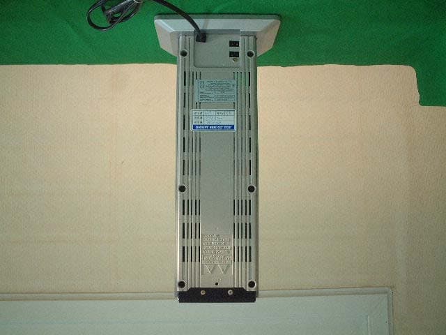
Click to zoom
Application Details
- Equipment Class
- DSS - Part 15 Spread Spectrum Transmitter
- Date of Grant
- Mar 18, 2004
- Application Purpose
- Original Equipment
- Date of Application
- Mar 18, 2004
- Equipment Note
- Speaker
- Frequency Range
- 2402.00000000 - 2480.00000000
- Company
- Samsung Electronics Co Ltd
- Country
- United States
Documents & Files
Document Text
Text extracted from the exhibit documents filed with the FCC. Open a document above to read the original.
Users Manual
DIGITAL HOME CINEMA SYSTEM HT-DB390 ASCLSMV-H/P TV DVD RECEIVER OPEN/CLOSE DVDTUNERAUX EZ VIEW NTSC/PAL SLOWSUB TITLE ASC TUNING/CH PL II R E TU R N M E N U I N F O MUTE MODE ENTER SOUND EDIT TEST TONERDS DISPLAY PTY–PTY+PTY SEARCH TA SLEEP LOGOREPEAT CANCELZOOM WIRELESS TUNER MEMORY PL II EFFECT VOLUME LSM V-H/P MOVIEMUSIC SUPER5.1 BAND MO/ST TV/VIDEOMODE DIMMER V I D E O COMPACT DIGITAL AUDIO COMPACT DIGITAL VIDEO Instruction Manual AH68-01285B THIS APPLIANCE IS MANUFACTURED BY: User's Manual Information Acknowledging Special Precautions and the FCC Industry Canada Notice Cautions Modifications not expressly approved by the party responsible for compliance could void the user's authority to operate the equipment. FCC compliance Information This device complies with part 15 of FCC Rules. Operation is subject to the following two conditions: 1. This device may not cause harmful interference, and 2. This device must accept any interference received. Including interference that may cause undesired operation. Information to User This equipment has been tested and found to comply with the limits for a Class B digital device, Pursuant to part 15 of the FCC Rules. These limits are designed to provide reasonable protection against harmful interference in a residential installation. This equipment generates, uses and can radiate radio Frequency energy and, if not installed and used in accordance with the instructions, may cause harmful interference to radio communications. However, there is no guarantee that interference will not occur in a particular installation. If this equipment does cause harmful interference to radio or television reception, which can be determined by turning the equipment off and on, the user is encouraged to try to correct the interference by one or more of the following measures: - Reorient or relocate the receiving antenna. - Increase the separation between the equipment and receiver - Connect the equipment into an outlet on a circuit different from that to which the receiver is connected. - Consult the dealer or an experienced radio/TV technician for help. 12 Safety WarningsPrecautions Ensure that the AC power supply in your house complies with the identification sticker located on the back of your player. Install your player horizontally, on a suitable base (furniture), with enough space around it for ventilation (3~4inches). Make sure the ventilation slots are not covered. Do not stack anything on top of the player. Do not place the player on amplifiers or other equipment which may become hot. Before moving the player, ensure the disc tray is empty. This player is designed for continuous use. Switching off the DVD player to the stand-by mode does not disconnect the electrical supply. In order to disconnect the player completely from the power supply, remove the main plug from the wall outlet, especially when left unused for a long period of time. Protect the player from moisture(i.e. vases) , and excess heat(e.g.fireplace) or equipment creating strong magnetic or electric fields (i.e.speakers...). Disconnect the power cable from the AC supply if the player malfunctions. Your player is not intended for industrial use. Use of this product is for personal use only. Condensation may occur if your player or disc have been stored in cold temperatures. If transporting the player during the winter, wait approximately 2 hours until the unit has reached room temperature before using. Phones During thunderstorms, disconnect AC main plug from the wall outlet. Voltage peaks due to lightning could damage the unit. Do not expose the unit to direct sunlight or other heat sources. This could lead to overheating and malfunction of the unit. The battery used with this product contain chemicals that are harmful to the environment. Do not dispose of batteries in the general household trash. PREPARATION Use of controls, adjustments or performance of procedures other than those specified herein may result in hazardous radiation exposure. CAUTION-INVISIBLE LASER RADIATION WHEN OPEN AND INTERLOCKS DEFEATED, AVOID EXPOSURE TO BEAM. This symbol indicates that dangerous voltage which can cause electric shock is present inside this unit. This symbol alerts you to important operating and maintenance instructions accompanying the unit. WARNING:To reduce the risk of fire or electric shock, do not expose this appliance to rain or moisture. CAUTION:TO PREVENT ELECTRIC SHOCK, MATCH WIDE BLADE OF PLUG TO WIDE SLOT, FULLY INSERT. Wiring the Main Power Supply Plug(UK Only) IMPORTANT NOTICE The main lead on this equipment is supplied with a moulded plug incorporating a fuse. The value of the fuse is indicated on the pin face of the plug and if it requires replacing, a fuse approved to BS1362 of the same rating must be used. Never use the plug with the fuse cover removed. If the cover is detachable and a replacement is required, it must be of the same colour as the fuse fitted in the plug. Replacement covers are available from your dealer. If the fitted plug is not suitable for the power points in your house or the cable is not long enough to reach a power point, you should obtain a suitable safety approved extension lead or consult your dealer for assistance. However, if there is no alternative to cutting off the plug, remove the fuse and then safely dispose of the plug. Do not connect the plug to a main socket as there is a risk of shock hazard from the bared flexible cord. Never attempt to insert bare wires directly into a main socket. A plug and fuse must be used at all times. IMPORTANT The wires in the main lead are coloured in accordance with the following code:– BLUE = NEUTRAL BROWN = LIVE As these colours may not correspond to the coloured markings identifying the terminals in your plug, proceed as follows:– The wire coloured BLUE must be connected to the terminal marked with the letter N or coloured BLUE or BLACK. The wire coloured BROWN must be connected to the terminal marked with the letter L …
Text truncated - open the document above for the full version.
Users Manual
Regulatory Information FCC compliance Information This device complies with part 15 of FCC Rules. Operation is subject to the following two conditions: 1. This device may not cause harmful interference, and 2. This device must accept any interference received. Including interference that may cause undesired operation. Information to User This equipment has been tested and found to comply with the limits for a Class B digital device, Pursuant to part 15 of the FCC Rules. These limits are designed to provide reasonable protection against harmful interference in a residential installation. This equipment generates, uses and can radiate radio Frequency energy and, if not installed and used in accordance with the instructions, may cause harmful interference to radio communications. However, there is no guarantee that interference will not occur in a particular installation. If this equipment does cause harmful interference to radio or television reception, which can be determined by turning the equipment off and on, the user is encouraged to try to correct the interference by one or more of the following measures: - Reorient or relocate the receiving antenna. - Increase the separation between the equipment and receiver - Connect the equipment into an outlet on a circuit different from that to which the receiver is connected. - Consult the dealer or an experienced radio/TV technician for help. FCC WARNING: This equipment may generate or use radio frequency energy. Changes or modifications to this equipment may cause harmful interference unless the modifications are expressly approved in the instruction manual. The user could lose the authority to operate this equipment if an unauthorized change or modification is made. RF Exposure Information: The antenna(s) used for this transmitter must be installed to provide a separation distance of at least 20 cm from all persons and must not be co-located or operating in conjunction with any other antenna or transmitter.
Users Manual
A-B Repeat Playback 26 • The A-B Repeat function will not work on an MP3 or JPEG disc. 2 Press Cursor button to move to REPEAT PLAYBACK display. • For a VCD or CD, press INFO button once. 1 Press INFObutton twice. A - A -? REPEAT : A— A - B REPEAT : A—B • The specified segment will be played repeatedly. 4 Press ENTER button at the end of the segment. • When ENTERbutton is pressed, the selected position will be stored in memory. 3 Press Cursor , buttons to select ‘A-’ and then press ENTERbutton at the beginning of the segment. To return to normal playback, press Cursor , buttons to select OFF. DVDVCDCD Repeat Playback Repeat playback allows you to repeatedly play a chapter, title, track (song), or directory (MP3 file). 25 Press REPEATbutton. • Each time the button is pressed during playback, the repeat playback mode changes as follows: DVD VCDCD MP3JPEG • Repeat playback operation is not possible with version 2.0 VCD discs if PBC is turned on. To use Repeat Playback on a VCD with PBC, you should set the PBC to OFF in the disc menu. (See page 31.) CHAPTER Repeatedly plays the selected chapter. TITLE Repeatedly plays the selected title. RANDOM Plays tracks in random order. (A track that has already been played may be played again.) TRACK Repeatedly plays the selected track. FOLDER Repeatedly plays all tracks in the selected folder. DISC Repeatedly plays the entire disc. OFF Cancels Repeat Playback. To Select a Repeat Playback Mode in the Disc Information Screen Press INFObutton twice. 1 Press Cursor button to move to REPEAT PLAYBACK display. 2 Press Cursor button to select the desired Repeat Playback mode. 3 DVD VCDCD * For MP3 and JPEG discs, you cannot select Repeat Play from the information display screen. Press ENTERbutton. 4 DVDVCDCDMP3JPEG Repeat Playback Options Note Note OPERATION 28 Zoom Function This function allows you to enlarge a particular area of the displayed image. Zoom (Screen Enlarge) Function DVDVCD Aspect Ratio DVD 2 Press Cursor , , , buttons to move to the area you want to enlarge. 1 Press ZOOM button. • Each time the button is pressed, the zoom level changes as follows: 3 Press ENTER button. Press EZ VIEWbutton. • Each time the button is pressed, the zoom function will switch between On and Off. • When a movie is played in Widescreen format, black bars at the top and bottom of the TV screen can be removed by pressing the EZ VIEWbutton. • This function will not work if the DVD is recorded with multi-camera angle format. • Black bars may not disappear because some DVD discs have a built-in horizontal to vertical ratio. 27 Angle Function This function allows you to view the same scene in different angles. DVD 2 Press Cursor button to move to ANGLE display. 1 Press INFObutton. 1/3 • Each time the button is pressed, the angle changes as follows: 3 Press Cursor , buttons or numeric buttons to select the desired angle. 2/3 3/3 1/3 1/3 • The Angle function works only with discs on which multiple angles have been recorded. Note Note OPERATION EZ VIEW OFFEZ VIEW ENTER SELECT 30 Moving Directly to a Scene/Song • The selected file will be played. • An MP3 or JPEG disc cannot be moved from the disc information screen. • When playing an MP3 or JPG disc, you cannot use , to move a folder. To move a folder, press (Stop) and then press , . DVDVCDCD MP3JPEG 2 Press Cursor , buttons or numeric buttons to select the desired title/track and then press ENTERbutton. 1 Press INFObutton. 01/05 001/0400:00:371/1 03/05 001/0020:00:011/1 01/05 001/0400:00:011/1 Moving to a Title/Track 4 Press Cursor , buttons or numeric buttons to select the desired chapter and then press ENTERbutton. 01/05 025/0400:00:011/1 Moving to a Chapter 6 Press the numeric buttons to select the desired time and then press ENTERbutton. 01/05 028/0401:30:001/1 Moving to a Specific Time 3 Press Cursor , buttons to move to Chapter display. Moving to a Chapter 01/05 025/0401:17:301/1 5 Press Cursor , buttons to move to time display. Moving to a Specific Time Press the numeric buttons. • You can press on the remote control to move directly to the desired title, chapter, or track. • Depending on the disc, you may not be able to move to the selected title or time. 29 Selecting Audio/Subtitle Language • Depending on the number of languages on a DVD disc, a different audio language (KOREAN, ENGLISH, JAPANESE, etc.) is selected each time the button is pressed. 2 Press Cursor , buttons or numeric buttons to select the desired audio language. 1 Press INFObutton twice. EN 2/3 JA 3/3 • You can use the SUBTITLE button on the remote control to select a subtitle language. • Depending on the disc, the Subtitle and Audio Language functions may not work. Audio Language Selection Function DVD Subtitle Language Selection Function DVD Note Note OPERATION KO 1/3KO 01/ 03OFF EN 02/ 03 JA 03/ 03 OFF / 03 2 Press Cursor button to move to SUBTITLE display. 1 Press INFObutton twice. 3 Press Cursor button or numeric buttons to select the desired subtitle. Using the Title Menu For DVDs containing multiple titles, you can view the title of each movie. Depending on the disc, this function may either not work at all or may work differently. 2 Press Cursor , button to move to ‘Title Menu’. DVD 1 Press MENU button. 3 Press ENTER button. • The title menu appears. 32 Press MENUbutton to exit the setup screen. Using Disc Menu You can use the menus for the audio language, subtitle language, profile, etc. DVD menu contents differ from disc to disc. DVD 31 2 • When playing a VCD (version 2.), this toggles between PBC ON and OFF. • When you select the disc menu that is not supported by the disc, the "This menu is not supported" message appears on the screen. 1 Press MENU button. Press Cursor , buttons to move to ‘DISC MENU’ and then press ENTERbutton. 4 Press ENTER button. 3 Press Cursor , , , buttons to select the desired item. PBC (Playback Control) Function When playing a VCD (version 2.0), you can select and view various scenes according to the menu screen. P…
Text truncated - open the document above for the full version.
Users Manual
21 Press MENUbutton. Press Cursor button to move to ‘Setup’ and then press ENTERbutton. 4 • Enter the old password, a new password, and confirm new password. • The setting is complete. 35 Press RETURNbutton to return to the previous level. Press MENUbutton to exit the setup screen. 3940 Press Cursor button to move to ‘PASSWORD’ and then press ENTER button. Press ENTER button. Enter the password and then press ENTERbutton. SETUP Setting the Password You can set the password for the Parental (rating level) setting. 4142 Setting the Wallpaper While watching a DVD, VCD, or JPEG CD, you can set the image you like as a wallpaper. • "LOGO COPYING" will be displayed on the TV screen followed by "LOGO COPIED". 21435 768 Press RETURNbutton to return to the previous level. Press MENUbutton to exit the setup screen. During playback, press PLAY/PAUSEbutton when the image you like comes up. Press MENUbutton. Press LOGO button. DVDVCDJPEG Press Cursor button to move to ‘Setup’ and then press ENTERbutton. Press Cursor button to move to ‘LOGO’ and then press ENTERbutton. Press MENU button to exit the setup screen. Press OPEN/CLOSE button to open and then close the disc tray. Press Cursor button to move to ‘USER’ and then press ENTERbutton. DVDVCDJPEG To Change the Wallpaper 1 During playback, press PLAY/PAUSEbutton when you see an image you like. Press LOGObutton. • "LOGO COPYING" will be displayed on the TV screen followed by "LOGO COPIED". 2 3 Press OPEN/CLOSE button to open and then close the disc tray. • The wallpaper is changed. Select this to set the Samsung Logo image as your wallpaper. Select this to set the desired image as your wallpaper. SETUP PAUSE LOGO COPYING PAUSE PAUSE LOGO COPYING PAUSE 21 43 Setting the Speaker ModeSetting the Test Tone Press MENUbutton. Press Cursor button to move to ‘Audio’ and then press ENTERbutton. In the Speaker Setup, press the ENTERbutton again. L: Front Speaker (L)C: Center SpeakerSW: Subwoofer R: Front Speaker (R)LS: Rear Speaker (L)RS: Rear Speaker (R) Press Cursor , , , buttons to move to the desired speaker and then press ENTERbutton. • For C, LS, and RS, each time the button is pressed, the mode switches alternately as follows: SMALL ➝ NONE. • For L and R, the mode is set to SMALL. • With (Dolby Pro Logic II), the delay time may be different for each mode. • With AC-3 and DTS, the delay time is set between 00 and 15mSEC. • Depending on PRO LOGIC and STEREO, the speaker mode may vary. Press RETURNbutton to return to the previous level. Press MENUbutton to exit the setup screen. 4344 Note SETUP SMALL: Select this when using the speakers. NONE: Select this when no speakers are installed. 21 Press MENUbutton. Press Cursor button to move to ‘Audio’ and then press ENTERbutton. 3 Press Cursor button to move to ‘TEST TONE’ and then press ENTERbutton. • The test tone will be sent to L ➝ C ➝ R ➝ RS ➝ LS ➝ SW in that order. If the button is pressed again at this time, the test tone will stop. To end the test tone, press TEST TONEbutton. Press TEST TONEbutton. • Test tone will be produced as follows: When playing a DVD or CD, this will work only in Stop mode. • Use this function to check that each speaker is correctly connected and that there is no problem. When manually testing using the TEST TONEbutton Multi-Channel Pro Logic Mode Start Setting the Delay Time 4546 5.3 ms 10.6 ms 15.9 ms • Setting REAR (SURROUND) SPEAKERS If the distance of Df is equal to the distance of Ds in the figure, set the mode as 0ms. Otherwise, change the setting according to the table. • Setting CENTER SPEAKER If the distance of Dc is equal to or longer than the distance of Df in the figure, set the mode as 0ms. Otherwise, change the setting according to the table. Distance between Df and Dc Delay Time Delay Time 1.3 ms 2.6 ms 3.9 ms 5.3 ms Distance between Df and Ds 50 100 150 200 200 400 600 Setting up the Speaker Delay Time When 5.1CH Surround Sound is played, you can enjoy the best sound if the distance between you and each speaker is the same. Since the sounds arrive at the listening position at different times depending on the placement of speakers, you can adjust this difference by adding a delay effect to the sound of the Center Speaker and Surround Speakers. Df: The distance from FRONT SPEAKER Dc: The distance from CENTER SPEAKER Ds: The distance from SURROUND SPEAKER Ideal CENTER SPEAKER placement It is desirable to place all speakers within this circle. Ideal SURROUND SPEAKER placement SETUP 2 1 Press MENUbutton. Press Cursor button to move to ‘Audio’ and then press ENTER button. • You can set the delay time for C between 00 and 05mSEC and for LS and RS between 00 and 15mSEC. 435 Press Cursor button to move to ‘DELAY TIME’ and then press ENTERbutton. Press Cursor , , , buttons to move to the desired speaker and then press ENTERbutton. Press Cursor , to set the Delay time. Press RETURNbutton to return to the previous level. Press MENUbutton to exit the setup screen. 47 Setting the Audio Quality You can adjust the balance and level for each speaker. 21 43 Press MENUbutton. Press Cursor button to move to ‘Audio’ and then press ENTERbutton. Press Cursor button to move to ‘SOUND EDIT’ and then press ENTERbutton. Press Cursor , , , buttons to select the desired item and then press ENTERbutton. Adjusting Front/Rear Speaker Balance • You can select between 00 and –06 and OFF. • The volume decreases as you move closer to –6. Adjusting Center/Rear/Subwoofer Speaker Level • The volume level can be adjusted in steps from +6dB to –6dB. • The sound gets louder as you move closer to +6dB and smaller as you get closer to -6dB. Method 1 When adjusting the audio quality using the setup screen Method 2 When manually adjusting with the SOUND EDIT button 21 Adjusting Front Speaker BalanceAdjusting Rear Speaker Balance Press SOUND EDITbutton and then press Cursor , . 3 Adjusting Center Speaker Level 45 Adjusting Rear Speaker LevelAdjusting Subwoofer Speaker Level Press RETURNbutton to return to the pr…
Text truncated - open the document above for the full version.
Cover Letter(s)
516-229, Chen Jiang Town, Huizhou-City, Guangdong-Province, China March 03, 2004 Federal Communications Commission Equipment Authorization Branch 7435 Oakland Mills Road Columbia, MD 21046 LETTER OF AUTHORIZATION To whom it may concern: We, the undersigned, hereby authorize DIGITAL EMC Co., Ltd., to act on our behalf in all manners relating to application for equipment authorization for FCC ID: A3LSWA1000 . Including signing of all documents relating to these matters. Any and all acts carried out by DIGITAL EMC Co., Ltd ., on our behalf shall have the same affect as acts of our own. This authorization is valid until further written notice from SAMSUNG Electronics Huizhou Co., Ltd. Sincerely, O-Won Seo R&D Management Group /Manager
Cover Letter(s)
516-229, Chen Jiang Town, Huizhou-City, Guangdong-Province, China March 03, 2004 Federal Communications Commission Equipment Authorization Branch 7435 Oakland Mills Road Columbia, MD 21046 In re : SAMSUNG Electronics Huizhou Co., Ltd. FCC ID : A3LSWA1000 FCC Part 15.247 Certification Request for Confidentiality Gentlemen: In accordance with 0.459 of CFR 47, SAMSUNG Electronics Huizhou Co., Ltd. hereby requests confidentiality of the Block diagram, Schematics, Parts list, Operational Description of the attached test report. These documents contain detailed system and equipment description and related information about the product which SAMSUNG Electronics Huizhou Co., Ltd. considers to be proprietary, confidential, and a custom design and, otherwise, would not release to the general public. Since this design is a basis from which future technological products will evolve, SAMSUNG Electronics Huizhou Co., Ltd. considers that this information would be of benefit to its competitors, and that the disclosure of the information in these documents would give competitors an unfair advantage in the market. Sincerely, O-Won SEO R&D Management Group /Manager
External Photos
SWA-1000 Photographs View 1 View 2
ID Label/Location Info
FCC ID: A3LSWA1000 FCC ID SAMPLE LABEL & LOCATION LABELLING REQUIREMENTS PER §2.925 The Label shown shall be permanently affixed at a conspicuous location on the device and be readily visible to the user at the time of purchase (SEE NEXT PAGE) FCC ID: A3LSWA1000 APPENDIX - 2 FCC ID: A3LSWA1000 Model No.: SWA-1000 This device complies with Part 15 of the FCC Rules. Operation is subject to the following two conditions: (1)this device may not cause harmful interference, and (2) this device must accept any interference received, including interference that may cause undesired operation.
Internal Photos
SWA-1000 Photographs View 1 View 2 View 3 View 4 View 5
Operational Description
CONFIDENTIAL http://www.solutionhere.com DWM3000 Datasheet Oct. 2002 Open Solution Co., Ltd. Open your eyes, Solution is here. OSMKDS0209-05R10 1 CONFIDENTIAL Open Solution Co., Ltd http://www.solutionhere.com Your Wireless Life! DWM3000 Datasheet FEATURES - Delivers Digital Audio & Data - Crystal Clear CD Quality Stereo Sound - 4:1 Audio Compression/Decompression - Supports 16/24bit Stereo audio data format - Supports 44.1/48 sampling frequency - Highly Robust Forward Error Correction - Modulation Mode: Frequency Hopping Spread Spectrum (FHSS) Adaptive Frequency Selection (AFS) Fixed Channel mode - TDD (Time Division Duplexing) Mode - Forward Data Rate: Stereo Audio Data (384Kbps) + Digital Data (16Kbps) - Reverse Data Rate: Digital Data (28.8Kbps) - 2.4 Bluetooth RF Chip Interface - Standard 16-bit 3-wire Stereo Audio Data Interface - SPI Interface for Non-Audio Data Transmission - 2.5V Power Supply for Core, 3.3V Power Supply for I/O Interface - Low Power Consumption : Less than 20 - Power Save Mode - 48-pin LQFP - Master/Slave Mode: I2C Master for external booting EEPROM I2C Slave for external MCU Interface - Broadcasting Mode: Point-to-Point and Point-to-Multi point broadcasting mode selection Master and single slave can communicate bi-directionally in broadcasting mode OVERVIEW DWM3000 is a digital audio processor IC encompassing apt-X TM audio compress/decompress algorithm for wireless transmission of crystal-clear CD quality audio data. For digital transmission the analog audio signals are sampled at 48 and converted to 1.536Mbps digital data through an external 16-bit stereo audio codec. The digitized data are apt-X TM 4:1 compressed to 384Kbps stream data for efficient transmission. Redundancy bits for forward error correction (FEC), synchronization flags, and control signals for time-division duplexing (TDD) are appended to form data frames for error-free transmission. In the receiver(Slave), synchronization flags and control data are first detected from the input stream. FEC decoder corrects any errors that may have been introduced during the transmission and produces error-free compressed audio data. The compressed audio is decompressed into 16-bit stereo PCM audio data through digital signal processing blocks. External audio codec converts the PCM data to 2-channel (left and right) analog audio signals. The Tx/Rx controller is in charge of several functions such as radio channel setup, frequency hopping for interference reduction and generation of control signal for TDD and external RF chip. In audio mode, the transmitter(Master) can send additional 16Kbps digital data simultaneously with stereo audio data. Full digital data communication of 400Kbps is also available in data mode where audio codec and compression/decompression block are bypassed. The receiver(Slave) supports 28.8Kbps reverse digital data communication that can be used for transmitter(Master) control or other applications. OSMKDS0209-05R10 2 CONFIDENTIAL Open Solution Co., Ltd http://www.solutionhere.com APPLICATION Wireless Headphone Wireless Headset Wireless Speaker/Microphone Wireless Keyboard/Mouse Wireless System control Short Distance Data Link Smart Toy OPERATIONAL BLOCK DIAGRAM Figure 1. DWM3000 Functional Block Diagram Reverse Channel Serial I/F Serial I/F Tx bit Stream Rx bit Stream Digital Audio Data L&R Audio Data compress RS Encoder 1/3 FEC Decoder Tx Controller Rx Controller Serial I/F Serial I/F Tx bit Stream Rx bit Stream Digital Audio Data L&R Audio Data compress 1/3 FEC Encoder RS Decoder Tx Controller Rx Controller RF Control RF Control OSMKDS0209-05R10 Contents of Table 3 DWM3000 Digital Audio/Data Processor IC CONTENTS OF TABLE 1 PIN INFORMATION........................................................................................ 6 1.1Pin Diagram.......................................................................................................... 6 1.2Pin Description (Sort by PIN Number) ............................................................... 7 1.3Pin Description (Sort by Functions)................................................................... 9 1.3.1Power Pins ....................................................................................................................... 10 1.3.2RESET/XIN-XOUT Pins ................................................................................................... 11 1.3.3Radio Interface Pins ......................................................................................................... 12 1.3.4I2C Master Pins ................................................................................................................14 1.3.4.1EEPROM Read Operation............................................................................................. 14 1.3.4.2EEPROM Write Operation ............................................................................................. 15 1.3.4.3I2C Master Bus Timing ................................................................................................. 16 1.3.5I2C Slave Pins ..................................................................................................................17 1.3.5.1Register Read/Write Operation...................................................................................... 18 1.3.5.1.1Register Read Operation ....................................................................................... 18 1.3.5.1.2Register Write Operation ....................................................................................... 18 1.3.5.2Tx/Rx Data Buffer Operation.......................................................................................... 19 1.3.5.2.1Tx Data Buffer Write Operation ............................................................................. 19 1.3.5.2.2Rx Data Buffer Read Operation............................................................................. 20 1.3.5.3I2C Slave pin timing .................…
Text truncated - open the document above for the full version.
Operational Description
SiW1502 Data Sheet April 16, 2001 60 0010 R01A SiW1502 DS Page 1 of 14 Silicon Wave, Inc. SiW1502 Radio Modem IC 1. INTRODUCTION The SiW1502 Radio Modem IC is part of Silicon Wave's Odyssey™ solutions for Bluetooth™ wireless communications. The SiW1502 IC combines a 2.4-GHz radio transceiver and GFSK modem with digital control functions meeting Bluetooth specifications. The SiW1502 IC is designed to work with the Silicon Wave SiW1602 Link Controller IC or other compatible ICs to enable production of Bluetooth wireless communication products. 2. FEATURES • Radio and modem with combined RF analog and digital CMOS circuits on a single integrated sili- con chip. • Fully qualified under Bluetooth Specification 1.1. − Suitable for Class 2 and 3 transmit power classifications, or Class 1 with external circuits. • Direct-conversion radio architecture with integrated VCO and frequency synthesizer requiring minimal external components. • Integrated analog-digital conversion circuits transform I/O signals between the radio and GFSK modem. • Integrated GFSK modem with digital modulation, channel filtering, AFC, symbol timing recovery, and bit-slicer. • Integrated 0-dBm transmit driver with eight output power levels. • Direct interface to Bluetooth controller ICs through a low pin-count, digital interface. • Optimized design for low power consumption, low cost, and small size. 3. APPLICATIONS The SiW1502 Radio Modem is …
Text truncated - open the document above for the full version.
Contact Information
Applicant
Jenni Chun(General Manager)
Test Firm
DT&C Co.,Changho Lee
Technical Specifications
| # | Rule Parts | Frequency Range | Power Output |
|---|---|---|---|
| 1 | 15C | 2.40 GHz - 2.48 GHz | 34.00 mW |
Other Applications from Samsung Electronics Co Ltd
A3LSMS741B
Aug 05, 2026Portable Handset
Equipment Class
6VL - 15E 6 GHZ Very Low Power DeviceA3LSMX940
Jul 31, 2026BT,BLE Tablet DTS,UNII a,b,g,n,ac,ax,be and digitizer
Equipment Class
DTS - Digital Transmission SystemA3LSMS741U
Jul 30, 2026Portable Handset
Equipment Class
6CD - 15E 6 GHz Low Power Dual ClientA3LSMX840
Jul 27, 2026BT,BLE Tablet DTS,UNII a,b,g,n,ac,ax and Digitizer
Equipment Class
DSS - Part 15 Spread Spectrum TransmitterA3LSMX848U
Jul 27, 2026WCDMA, LTE, 5G NR Tablet BT,BLE, DTS,UNII a b g n ac ax and Digitizer
Equipment Class
JBP - Part 15 Class B Computing Device Peripheral