A3LWEA403IWLAN Access Point
Samsung Electronics Co Ltd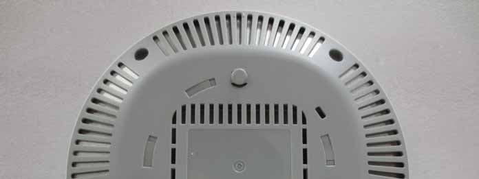
Click to zoom
Application Details
- Equipment Class
- NII - Unlicensed National Information Infrastructure TX
- Date of Grant
- Jul 24, 2014
- Application Purpose
- Original Equipment
- Date of Application
- Jul 09, 2014
- Equipment Note
- WLAN Access Point
- Frequency Range
- 5660.00000000 - 5720.00000000
- Company
- Samsung Electronics Co Ltd
- Country
- United States
Documents & Files
Document Text
Text extracted from the exhibit documents filed with the FCC. Open a document above to read the original.
Users Manual
Names and Functions Front View Rear View Ethernet Port DC Input Ethernet Port (PoE) Factory Reset Switch Console Port Dust covers are installed on power ports (DC 48 V/0.75 A), Ethernet ports and console ports (CONSOLE). Remove the covers before use. Interface Port NameDescription Status LED Displays the status information of the WEA400 Series via LED. DC InputUsed when a power adapter is used for power supply. Ethernet Port (PoE)Supports 1000 BASE-T Gigabit Ethernet and PoE IEEE 802.3af/802.3at. Ethernet PortSupports 1000 BASE-T Gigabit Ethernet. Console Port Used for checking the operational status of the WEA400 series and for CLI input. Factory Reset Switch Used for initialization when commencing factory shipment of the WEA400 series. Status LED Introduction What is the WEA400 series? The WEA400 series is an AP for the Samsung WE wireless LAN, which connects a UE such as a smart phone, a tablet PC or a laptop that supports the wireless LAN to a wired network. The WEA400 series supports the following features: - IEEE 802.11a/b/g/n/ac standard - PoE (Power over Ethernet) IEEE 802.3af/802.3at - WEA412i: 2 × 2 MIMO (Multiple Input Multiple Output) - WEA403i/403e/413i: 3 × 3 MIMO (Multiple Input Multiple Output) - Wireless LAN through both 2.4 GHz and 5 GHz bandwidth simultaneously Components After unpacking the WEA400 series, check whether all of the following components are included. WEA403i/412i/413iWEA403e Common merchandise Mounting Bracket 5 M3 × L6 screws (Including 1 spare) Installation Manual Security Torx (T10) ScrewPlastic 4 anchors M4 × L28 4 screws - It is recommended to keep all packaging materials and the box. - The power adapter and the external antenna for WEA403e are sold separately. When necessary, please contact the place of purchase. This manual describes the configuration of the Wireless Enterprise WEA400 series and its installation procedures. The installation procedures are described based on the WEA403i/412i/413i configurations. The same installation procedures apply to the WEA403e model, except for the antenna installation. Installation The WEA400 series can be installed on ceilings or walls. Please check whether all the components are included before installation. Before Installation Safety Requirements Risks may be caused when the following safety warnings are not properly observed. For safe use, make sure to be well-informed. - There is an electrical risk with the product. Make sure that the power is off during installation and do not proceed with the installation when there is current leakage. Use of products with current leakage may cause serious electrical shock to the user. - Wear anti-static gloves or take appropriate actions to prevent ESD when handling the product. - Do not connect a phone line connector to the Etherner port. It may damage the product. - This product must be connected to ta power supply in compliance with IEEE 802.3af/at or to a limited power supply in compliance with IEC/EN/UL 60950-1. - This product must be installed or removed only by appropriately-trained service personnel. - This product operates with SELV (Safety Extra Low Voltage) according to IEC/EN/UL 60950-1. - All interconnecting equipment including this product must be installed within the same building. For details, refer to Environment A of IEEE 802.3af/at standard. - This product must be installed with at least 3 m or more distance from the WiMAX/3G/4G repeater or antenna. Installation Instructions The instructions below must be observed when installing. - It must be installed in a place that can be easily accessed for product installation, cable connection and maintenance. - The PoE LAN cable must be always installed away from any electrical interference source such as power lines, fluorescent lights or transmitters. - The PoE LAN cable must be CAT 5E or higher. - When PoE is unavailable, a power adapter (sold separately) can be used. The 3-pin (including ground) power socket that supplies 100~240 V AC, 50~60 Hz must be located within 2 m from each equipment and the power must be supplied through an independent circuit breaker. It is recommended to use the equipment that uses a filter or a surge. Installation on Ceilings (When the ceiling type is T-bar) - When incorrectly installed on the ceiling, the WEA400 series may drop onto a person or equipment. Therefore, make sure to fix it firmly. - If the ceiling type is not T-Bar, please refer to the ‘Installation Manual’ provided separately. For this installation manual, please contact the dealer. 1. Remove the holding tape that was attached to fix the ceiling clip. Holding tape 2. Open the ceiling clip so that it is wider than the width of the T-bar. 3. Move the ceiling clip so that it is appropriate for the T-bar width. Status LED LEDStatus Description System start status White On Initial LED status Blue On Device reset and test in progress Red On Booting failure (Device reset failure) Provisioning Status Red, green and off repeated APC connection in progress (Network link normal) Green blinking CAPWAP connection in progress (APC server connection normal) Normal operation status Green On When there is no connected wireless UE Blue On When there is a connected wireless UE Upgrade Green blinking Software upgrade in progress Error status Red blinking Physical connection error of network Yellow blinking IP address conflict Purple blinking Dynamic IP address allocation failure Bluish-green blinking Logical connection error of network Red, green and off repeated Wireless interface error WEA400 Series Quick Installation Manual 4. Use a hammer to insert 4 plastic anchors into the drilled holes on the wall. Align the inserted plastic anchors and the screw holes of the bracket. Fix the bracket to the wall by fastening four M4 × L28 screws. 5. Insert a LAN cable into the Ethernet port (PoE) on the back side of the WEA400 series. If PoE is not supported, connect the power adapter to the DC input on the back of the WEA400 series. The wal…
Text truncated - open the document above for the full version.
Attestation Statements
SAMSUNG ELECTRONICS FCC DFS Uniform Spreading Declaration Date: May 28, 2014 Federal Communications Commission Authorization and Evaluation Division 7435 Oakland Mills Road Columbia, MD 21046 Attn: OET Dept. Product/ Model Number: Access Point/WEA403i Regarding Uniform Spreading requirements for DFS operation identified in FCC 06-96 in ET Docket 03-122; "Uniform Channel Spreading: The spreading of U-NII device Operating Channels over the 5250-5350 MHz and/or 5470-5725 MHz bands to avoid dense clusters of devices operating on the same Channel." We declare the device provides on aggregate a Uniform Spreading of the Operating Channels across the entire band. This applies to the 5250- 5350 MHz and/or 5470-5725 MHz bands. Name: Suchong Chang Date: May 28, 2014 Title: Principal Engineer Signature of applicant:
Attestation Statements
SAMSUNG ELECTRONICS FCC UNII Device 5600-5650MHz Band Non- Transmission Restrictions Declaration Date: May 28, 2014 Federal Communications Commission Authorization and Evaluation Division 7435 Oakland Mills Road Columbia, MD 21046 Attn: OET Dept. Product/ Model Number: Access Point/WEA403i Regarding restrictions for operation in the 5600 - 5650 MHz band, as described in FCC KDB notice 443999 D01 Approval of DFS UNII Devices v01 "Interim Plans to Approve UNII Devices Operating in the 5470 - 5725 MHz Band with Radar Detection and DFS Capabilities", We declare that the device will not transmit on channels which overlap the 5600 - 5650 MHz band. Name: Suchong Chang Date: May 28, 2014 Title: Principal Engineer Signature of applicant:
Attestation Statements
Ver. 2600-00FK1RGA4 5.0 WEC8500/WEC8050 (APC) Operation Manual COPYRIGHT This manual is proprietary to SAMSUNG Electronics Co., Ltd. and is protected by copyright. No information contained herein may be copied, translated, transcribed or duplicated for any commercial purposes or disclosed to the third party in any form without the prior written consent of SAMSUNG Electronics Co., Ltd. TRADEMARKS Product names mentioned in this manual may be trademarks and/or registered trademarks of their respective companies. This manual should be read and used as a guideline for properly installing and operating the product. All reasonable care has been made to ensure that this document is accurate. If you have any comments on this manual, please contact our documentation centre at the following homepage: Homepage: http://www.samsungdocs.com ©2013~2014 SAMSUNG Electronics Co., Ltd. All rights reserved. INTRODUCTION © SAMSUNG Electronics Co., Ltd. page 3 of 528 INTRODUCTION Purpose This manual describes the overview, management, and setup of WEC8500/WEC8050 that is a Samsung Wireless Enterprise (W-EP) Access Point Controller (APC). This manual is written for WEC8500 version 1.4.4, WEC8050 version 1.0.0. Document Content and Organization This manual consists of ten Chapters, three Annexes, and a list of Abbreviations. CHAPTER 1. Access Point Controller System Overview This chapter describes the main functions, network configuration, external configuration and service scenario of APC. CHAPTER 2. Basic System Configuration This chapter describes how to configure to use Command Line Interface (CLI) and Web UI. CHAPTER 3. Data Network Function This chapter describes how to set up the data network such as interface, Virtual Local Area Network (VLAN), L3, or Quality of Service (QoS), etc. of APC. CHAPTER 4. AP Connection Management This chapter describes the connection management function of APC and Samsung W-EP wireless LAN Access Point (AP). CHAPTER 5. WLAN Management This chapter describes how to set up the Wireless Local Area Network (WLAN) of APC. CHAPTER 6. Wi-Fi Configuration This chapter describes how to configure the Wireless Fidelity (Wi-Fi) of APC, QoS, and country code. INTRODUCTION © SAMSUNG Electronics Co., Ltd. page 4 of 528 CHAPTER 7. WLAN Additional Service This chapter describes how to set up WLAN additional services available in the APC. CHAPTER 8. Security This chapter describes how to set up security related setting such as Remote Authentication Dial-In User Service (RADIUS) server available in the APC, unauthorized AP detection and blocking function, guest access, WEB pass-through, Network Address Translation (NAT), firewall function, etc. CHAPTER 9. IP Application This chapter describes the Internet Protocol (IP) application functions available in the APC such as Domain Naming Service (DNS), Network Time Protocol (NTP), File Transfer Protocol (FTP)/sFTP, or Telnet/SSH. CHAPTER 10. System Management This chapter describes the various system management functions available in the APC. ANNEX A. CLI Command Structure Command structure available in the CLI of APC. ANNEX B. Open Source Announcement (WEC8500/WEC8050) Open source list used in the APC and its license notice. ANNEX C. Open Source Announcement (WEA302/WEA303/WEA312/ WEA313/WEA403/WEA412) Open source list used in the Samsung W-EP wireless LAN AP and its license notice. ABBREVIATION Describes the acronyms used in this manual. Conventions The following types of paragraphs contain special information that must be carefully read and thoroughly understood. Such information may or may not be enclosed in a rectangular box, separating it from the main text, but is always preceded by an icon and/or a bold title. NOTE Indicates additional information as a reference. INTRODUCTION © SAMSUNG Electronics Co., Ltd. page 5 of 528 Console Screen Output The lined box with ‘Courier New’ font will be used to distinguish between the main content and console output screen text. ‘Bold Courier New’ font will indicate the value entered by the operator on the console screen. Revision History VERSION DATE OF ISSUE REMARKS 5.0 05. 2014. - Updated the content overall in accordance with the package version 2.0.0 4.0 01. 2014. - Changed contents 1.3.1 WEC8500 Configuration and Functions 4.2.6.3 Tech Support Information 3.0 10. 2013. - Updated the content overall in accordance with the package version (WEC8500 version 1.4.4, WEC8050 version 1.0.0) - Added contents for WEC8050 2.0 06. 2013. - Updated the content overall in accordance with the package version 1.3.0 - Added contents 3.4.6 OS-AWARE 7.4.2 DPC Configuration 7.4.3 DCS Configuration 7.4.4 CHDC Configuration - Changed contents 7.10 Clustering 10.8.2 System Upgrade 1.0 03. 2013. First Version TABLE OF CONTENTS © SAMSUNG Electronics Co., Ltd. page 6 of 528 TABLE OF CONTENTS INTRODUCTION 3 Purpose ...................................................................................................................................................... 3 Document Content and Organization ....................................................................................................... 3 Conventions ............................................................................................................................................... 4 Console Screen Output ............................................................................................................................. 5 Revision History ......................................................................................................................................... 5 CHAPTER 1. Access Point Controller System Overview 19 1.1 APC Overview .......................................................................................................................... 19 1.2 Network Configuration ............................................................................................................ 21 1.3 APC Configuration…
Text truncated - open the document above for the full version.
Attestation Statements
CHAPTER 6. Wi-Fi Configuration © SAMSUNG Electronics Co., Ltd. page 251 of 528 Configuration using Web UI In the menu bar of <WEC Main window>, select <Configuration> and then select the <Radio> <802.11a/n> <802.11h> menu in the sub-menus. Figure 128. Configuring 802.11h POWER CONSTRAINT: Power constraint value (0-100) CHANNEL SWITCH: Enables channel switch announcement. RESTRICTION MODE: Configures transmission restriction. CHANNEL SWTICH COUNT: Enter a waiting time until channel switching announcement. Target Beacon Transmission Times (TBTT) CHAPTER 6. Wi-Fi Configuration © SAMSUNG Electronics Co., Ltd. page 252 of 528 6.4 Country Code You can use a country code to restrict the number of channels that can be used in an AP and the maximum transmission power of each channel. Configuration using CLI To configure the country code function, go to country mode first by executing the following command. APC# configure terminal APC/configure# country APC/configure/country# [Global Country Code Configuration] If you configure a global country code, the country code can be specified to all the connected APs at the same time. The command is shown below. set-global [COUNTRY_CODE] [VALUE] Parameter Description COUNTRY_CODE Country code to configure VALUE Environment configuration (both/outdoor/indoor/none) To check the configuration information, use the ‘show country global-config’ command. [AP Country Code Configuration] To configure a country code, execute the command as follows: set-ap [AP_ID] [COUNTRY_CODE] [VALUE] Parameter Description AP_ID AP ID (range: 1-500) COUNTRY_CODE Country code to configure VALUE Environment configuration (both/outdoor/indoor/none) To check the configuration information, use the ‘show country ap-config [AP_ID]’ command. CHAPTER 6. Wi-Fi Configuration © SAMSUNG Electronics Co., Ltd. page 253 of 528 [Editing Country Code] You can add or delete an operation channel per country and change maximum transmission power per channel. The command used to add or delete a channel per country is shown below. add-channel [COUNTRY_CODE] [CHANNEL_NUMBER] [MAX_TX_POWER]: Adds a channel. del-channel [COUNTRY_CODE] [CHANNEL_NUMBER]: Deletes a channel. Parameter Description COUNTRY_CODE Country code to configure CHANNEL_NUMBER Channel to configure. MAX _TX_POWER Maximum transmission power per channel. The command used to change maximum transmission power value of a channel for a specific country code is shown below. max-tx-power [COUNTRY_CODE] [CHANNEL_NUMBER] [MAX_TX_POWER] Parameter Description COUNTRY_CODE Country code to configure CHANNEL_NUMBER Channel to configure. MAX _TX_POWER Maximum transmission power per channel. To check the configuration information, use the ‘show country information [COUNTRY_ CODE]’ command. Parameter Description COUNTRY_CODE Country code to configure CHAPTER 6. Wi-Fi Configuration © SAMSUNG Electronics Co., Ltd. page 254 of 528 Configuration using Web UI In the menu bar of <WEC Main window>, select <Configuration> and then select the <Controller> <Country> menu in the sub-menus. Figure 129. Country code window (1) [Global Country Code Configuration] 1) Select a country in the DEFAULT COUNTRY drop-down list of Configured Country Code item. (Only an authenticated country code is supported.) 2) Select an environment in the DEFAULT ENVIRONMENT drop-down list. Both: The terminal operation environment includes all the environments. Outdoor: The terminal operation environment is outdoor. Indoor: The terminal operation environment is indoor. Non-country: A terminal is operating under non-country entity. 3) Click the <Apply> button to apply. [Editing Country Code] In the Edit Country Code item, you can add or delete an operation channel per country or change maximum transmission power per channel. 1) Select a country in the COUNTRY drop-down list of Edit Country Code item. (Only an authenticated country code is supported.) 2) Select a channel to add in the MAX TX POWER LEVEL (5 GHZ/2.4 GHZ) and enter maximum transmission power level (0-30). 3) In the MAX TX POWER LEVEL (5 GHZ/2.4 GHZ), unselect a channel to delete. 4) Click the <Apply> button to apply. CHAPTER 6. Wi-Fi Configuration © SAMSUNG Electronics Co., Ltd. page 255 of 528 [AP Country Code Configuration] In the menu bar of <WEC Main window>, select <Configuration> and then select the <Access Points> <General> menu in the sub-menus. Figure 130. Country code window (2) After selecting COUNTRY and ENVIRONMENT, click the <Apply> button. CHAPTER 7. WLAN Additional Services © SAMSUNG Electronics Co., Ltd. page 256 of 528 CHAPTER 7. WLAN Additional Services In this chapter, how to configure WLAN additional services such as wireless terminal management, spectrum analysis, Call Admission Control (CAC) and Radio Resource Management (RRM), etc. is described. 7.1 Managing Wireless Terminal 7.1.1 Information Retrieval Functions Configuration using CLI Using the following command, you can retrieve the information of a wireless terminal being serviced by the APC. show station summary: When you enter this command, the summary information of all the wireless terminals connected to the APC is retrieved. show station summary ap [AP_ID]: The information of wireless terminals of each AP is retrieved. show station summary bssid [BSSID_ID]: The information of wireless terminals of each BSSID is retrieved. show station summary wlan [WLAN_ID]: The information of wireless terminals of each WLAN is retrieved. show station detail [MAC_ADDRESS]: The detail information of a wireless terminal that has a specific MAC address is retrieved. show station stats ap-80211-stats [MAC_ADDRESS]: The WI-FI statistics information of a wireless terminal is retrieved. show station association history [MAC_ADDRESS]: The connection history of a wireless terminal is retrieved. show station stats debug all: The debug statistics information of a wireless terminal is retrieved. show station stats management_…
Text truncated - open the document above for the full version.
Attestation Statements
WEA 403i Integrated Antenna Features/Specifications Frequencies [MHz] 2,400-2,483/4,905-5,845 Configuration 6 of 2.4GHz, 6 of 5 GHz 3 of dual band Gain [dBi] Service ANT: [email protected]/6@5 GHz Monitoring ANT: 5.5 @2.4 GHz/6.5 @5GHz VSWR (max) Service:2.2, Montor:3.0 Polarization Linear (Vertical) Antenna Type Omni-directional Mounting Integrated Radiation Patterns Service BLUE 5GHz Service GREEN 5GHz Service BLACK 5GHz Service RED 5GHz Service WHITE 5GHz Service BLUE 2.4GHz Service GREEN 2.4GHz Service WHITE 2.4GHz Service YELLOW 5G Hz Service BLACK 2.4GHz Service RED 2.4GHz Service YELLOW 2.4GHz Monitoring GREEN 2.4GHz Monitoring RED 2.4GHz Monitoring YELLOW 2.4GHz Monitoring GREEN 5GHz Monitoring RED 5GHz Monitoring YELLOW 5GHz
Cover Letter(s)
SAMSUNG ELECTRONICS FCC UNII Device DFS Operation Declaration Date: July 2, 2014 Federal Communications Commission Authorization and Evaluation Division 7435 Oakland Mills Road Columbia, MD 21046 Attn: OET Dept. Product/ Model Number: Access Point/WEA403i Regarding restrictions for operation in the 5470 - 5725 MHz band; We declare that the device meets all requirements for operation in the 5470 - 5725 MHz band as specified in FCC KDB notice 443999 D01 Approval of DFS UNII Devices v01 "Interim Plans to Approve UNII Devices Operating in the 5470 - 5725 MHz Band with Radar Detection and DFS Capabilities". List of attachments and supporting documentation: FCC UNII Device DFS Operation Declaration [this document] FCC DFS 5600 - 5650 MHz Band Non-Transmission Declaration FCC DFS Uniform Spreading Declaration User's Manual Professional Installation Guide Name: Suchong Chang Date: July 2, 2014 Title: Principal Engineer Signature of applicant:
Cover Letter(s)
SAMSUNG ELECTRONICS 13.06.2014 Federal Communications Commission Equipment Authorization Branch 7435 Oakland Mills Road Columbia, MD 21046 Request for Confidentiality Company name: Samsung Electronics Co., Ltd FCC ID: A3LWEA403I FCC Part 15 Certification Gentlemen, Pursuant to 47 CFR 0.457(d)(1)(ii) and 0.459 Samsung Electronics Co., Ltd hereby requests permanent confidentiality of the following documents for the subject application: Exhibit Type File Name Description Block Diagram Block Diagram(WEA403i).pdf Block Diagram Operational Description Operational Description(WEA403i).pdf Operational Description Schematics Schematics(WEA403i).pdf Schematics Parts / BOM Part List(WEA403i).xls Parts List / BOM Note: Any exhibit NOT granted Confidential status is viewable on the FCC website as soon as the Grant is issued. Reason why the material should be withheld from public inspection: These documents contain detailed system, equipment description and related information about the product which Samsung Electronics Co., Ltd considers proprietary, confidential, and a custom design not otherwise available to the general public. State why the information is a “trade secret;” Since the design is a basis from which future products will evolve Samsung Electronics Co., Ltd considers that this information would be of significant benefit to its competitors and that disclosure would give competitors an unfair advantage in the marketplace. Trade secret” information is information which is not generally known or reasonably ascertainable, by which a business can obtain an economic advantage over competitors. The information is not normally released to any party or person outside the company. Sincerely, Signature: Name: Suchong Chang Company: Samsung Electronics Co., Ltd. Title: Principal Engineer Date: 6-13-2014
Cover Letter(s)
Date : Jan. 10, 2014 Rev : 2.1 FCC Agent Authorization Letter HACS-F004 FCC Agent Authorization Letter HCT America LLC ([email protected]) 44364 S. Grimmer Blvd. Fremont, CA 94538 TEL: +1.510.933.8848, Fax: +1.510.933.8849 Page 1 of 2 This document is electronically controlled. Hard copy documents are uncontrolled. Please check all hard copies against the controlled electronic copy to ensure validity. This document is the confidential property of HCT America LLC. It may not be forwarded or reproduced in whole or in part without written permissions from HCT America LLC Date : Jan. 10, 2014 Rev : 2.1 REVISION TABLE Rev Description of Change Date Approved 1.0 Original Release(Obsolete) 06/14/2012 QM 2.0 Updated template(Obsolete) 10/01/2012 QM 2.1 Updated address 01/10/2014 QM HACS-F004 FCC Agent Authorization Letter HCT America LLC ([email protected]) 44364 S. Grimmer Blvd. Fremont, CA 94538 TEL: +1.510.933.8848, Fax: +1.510.933.8849 Page 2 of 2 This document is electronically controlled. Hard copy documents are uncontrolled. Please check all hard copies against the controlled electronic copy to ensure validity. This document is the confidential property of HCT America LLC. It may not be forwarded or reproduced in whole or in part without written permissions from HCT America LLC SAMSUNG ELECTRONICS DATE : May, 30, 2014 To: Federal Communications Commission Authorization and Evaluation Division 7435 Oakland Mills Road Columbia, MD To whom it may concern: Subject : FCC Agenct Authorization Letter for FCC ID : A3LWEA403I We, the undersigned, hereby authorize HCT Co., Ltd. to act on our behalf in all manners relating to application for equipment authorization, including signing of all documents relating to these matters. Any and all acts carried out by HCT Co., Ltd. on our behalf shall have the same effect as acts of our own. We, the undersigned, hereby certify that we are not subject to a denial of federal benefits, that includes FCC benefits, pursuant to Section 5301 of the Anti-Drug Abuse Act of 1988, 21 U.S.C. 853(a). We recognize that we are still responsible for the terms and conditions outlined in the HCT America Client Services Agreement. This authorization is valid until further written notice from the applicant. Sincerely, Signed by: Company Name : Samsung Electronics CO. Ltd. Company Address : (Maetan dong)129, Samsung-ro, Yeongtong-gu, Suwon-si, Gyeonggi-do 443-742, Korea Contact Person Name/Title (in print) : Suchong Chang/Principal Engineer HACS-F004 FCC Agent Authorization Letter Rev : 2.1
Cover Letter(s)
1 Describe how any software/firmware update will be obtained, do wnloaded, and installed. The upgrade control message is communic ated via DTLS and the software binary image is downloaded by using sFTP. 2 Describe all the radio frequency parameters that are modified by any software/firmware without any hardware changes. Are these parameters in some way limited, such that, it will not exceed the authorized parameters? - all the radio frequency parameters that are modified by any s oftware - These parameters is limited in UI. (See file 1) 3 Are there any authentication protocols in place to ensure that the source of the software/firmware is legitimate? If so, describe in details; if not, explain how the software is secured from modification. 4 Are there any verification protocols in place to ensure that t he software/firmware is legitimate? If so, describe in details. 5 Describe, if any, encryption methods used.6 For a device that can be configured as a master and client (wi th active or passive scanning), explain how the device ensures compliance for each mode? In par ticular if the device acts as master in some band of operation and client in another; how is compliance ensured in each band of operation? - Our device is operated as master- UI(WEB) is limited to ensure compliance and device also has l imitation to ensure compliance 1 How are unauthorized software/firmware changes prevented? Refer to the 3 ~ 5 of General Description 2 Is it possible for third parties to load device drivers that c ould modify the RF parameters, country of operation or other parameters which impact device co mpliance? If so, describe procedures to ensure that only approved drivers are loaded. - No. it is not possible for third parties to load device drive rs that could modify the RF parameters 3 Explain if any third parties have the capability to operate a US sold device on any other regulatory domain, frequencies, or in any manner that is in vio lation of the certification. No for devices are authorization in U.S 4 What prevents third parties from loading non-US versions of th e software/firmware on the device? HW is limited to US. The non-US versions software/firmware can' t change 5 For modular devices, describe how authentication is achieved w hen used with different hosts. Not modular devices 1 To whom is the UI accessible? (Professional installer, end use r, other.) Professional installer, or IT Manager a) What parameters are viewable to the professional installer/e nd-user? -. See file 1 b) What parameters are accessible or modifiable to the professi onal installer? -. See file 1 i) Are the parameters in some way limited, so that the ins tallers will not enter parameters that exceed those authorized? Yes SOFTWARE SECURITY REQUIREMENTS FOR U-NII DEVICES Baisically, AP and APC is authenticated each other. All control messages between AP and APC is encrypted via DTLS.Regarding to the binary image file for upgrade, AP checks the C RC value for integrity test and the header information of software binary im age after downloading software binary image received from APC or the upgr ade server. If the software may be modified, CRC checksum error happends or AP will SOFTWARE SECURITY DESCRIPTION SOFTWARE CONFIGURATION DESCRIPTION USER CONFIGURATION GUIDE General Description Third-Party Access Control In accordance with FCC KDB 594280 D02 v01r01, the new Software Security requirements for U-NII Devices, the following informat ion is provided to describe the security features of the softwa re in this device. all the radio frequency parameters that all the radio frequency parameters that all the radio frequency parameters that ii) What controls exist that the user cannot operate the de vice outside its authorization in the U.S.? User can't control device's country information for devices are authorization in the U.S. c) What configuration options are available to the end-user? -. See file 1 i) Are the parameters in some way limited, so that the ins tallers will not enter parameters that exceed those authorized? Yes ii) What controls exist that the user cannot operate the de vice outside its authorization in the U.S.? User can't control device's country information for devices are authorization in the U.S. d) Is the country code factory set? Can it be changed in the UI ? No for devices are authorization in U.S i) If so, what controls exist to en…
Text truncated - open the document above for the full version.
Contact Information
Applicant
Jenni Chun(General Manager)
Test Firm
HCT Co., LTDSang Lee
Technical Specifications
| # | Rule Parts | Frequency Range | Power Output |
|---|---|---|---|
| 4 | 15E | 5.66 GHz - 5.72 GHz | 78.00 mW |
Other Applications from Samsung Electronics Co Ltd
A3LSMS741B
Aug 05, 2026Portable Handset
Equipment Class
6VL - 15E 6 GHZ Very Low Power DeviceA3LSMX940
Jul 31, 2026BT,BLE Tablet DTS,UNII a,b,g,n,ac,ax,be and digitizer
Equipment Class
DTS - Digital Transmission SystemA3LSMS741U
Jul 30, 2026Portable Handset
Equipment Class
6CD - 15E 6 GHz Low Power Dual ClientA3LSMX840
Jul 27, 2026BT,BLE Tablet DTS,UNII a,b,g,n,ac,ax and Digitizer
Equipment Class
DSS - Part 15 Spread Spectrum TransmitterA3LSMX848U
Jul 27, 2026WCDMA, LTE, 5G NR Tablet BT,BLE, DTS,UNII a b g n ac ax and Digitizer
Equipment Class
JBP - Part 15 Class B Computing Device Peripheral