A3LZMC3000NMicrowave Oven
Samsung Electronics Co Ltd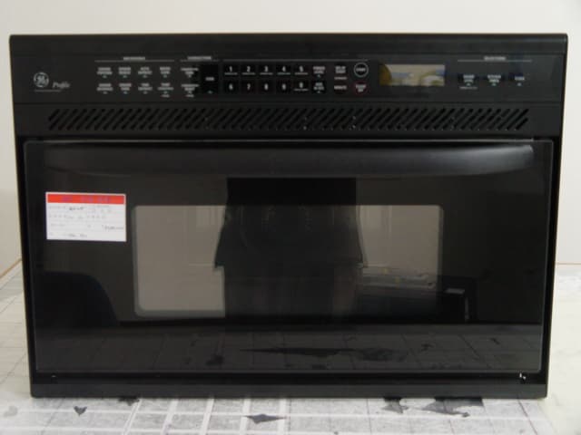
Click to zoom
Application Details
- Equipment Class
- 8CC - Part 18 Consumer Device
- Date of Grant
- Jan 13, 2005
- Application Purpose
- Original Equipment
- Date of Application
- Jan 13, 2005
- Equipment Note
- Microwave Oven
- Frequency Range
- 2450.00000000 - 2450.00000000
- Company
- Samsung Electronics Co Ltd
- Country
- United States
Documents & Files
Document Text
Text extracted from the exhibit documents filed with the FCC. Open a document above to read the original.
Users Manual
Use and Care Guide Built-In Microwave⁄Convection Oven GE Appliances164D3370P29149-40361 06-03 JR Safety Instructions................3–5 Precautions to Avoid Possible Exposure to Excessive Microwave Energy ..........2 Operating Instructions, Tips Aluminum Foil ...............................4, 24, 26 Clock........................................................8, 9 Combination Cooking ........................25–28 Combination Roast .........................27, 28 Cooking by Temperature......................26 Cooking by Time ...................................25 Control Panel..........................................8, 9 Convection Cooking ..........................23, 24 Cooking by Temperature......................24 Cooking by Time ...................................23 Cooking Reference Guide .......................29 Cookware and Accessories .....................11 Features ......................................................7 Microwave Cooking .......................6, 13–22 Add 30 Seconds ....................................14 Auto Defrost ....................................17, 18 Cooking by Temperature......................16 Cooking by Time.............................13, 14 Cooking Complete Reminder ................7 Defrosting by Time ...............................15 Delay Start/Reminder ...........................14 Delayed Cooking...................................12 Express Cook Feature...........................14 Hold Time ..............................................12 Kitchen Timer ........................................12 Microwaving Tips ...................................6 Power Levels ..............6, 8, 12, 13, 15, 16 Sensor Beverage...................................19 Sensor Cook ..........................................21 Sensor Cooking Control Guide............22 Sensor Popcorn ....................................19 Sensor Reheat.......................................20 Sound Level Feature ............................14 Oven Shelf......................4, 7, 11, 19–21, 31 Temperature Probe ............................4, 7–9, 16, 24, 26–28, 31 What Your Oven Can Do .........................10 Problem Solver...........................32 Care and Cleaning..............30, 31 Light Bulb Replacement ..........................31 Installation......................................31 Adapter Plugs...........................................31 Extension Cords .......................................31 Grounding Instructions ...........................31 Consumer Services..................35 Appliance Registration ..............................2 Important Phone Numbers .....................35 Model and Serial Number Location .........2 Warranty ....................................Back Cover Model: JEB1095 Microwave power output of this oven is 800 watts. (IEC-705 Test Procedure) 2 HELP US HELP YOU... Before using your oven, read this guide carefully. It is intended to help you operate and maintain your new microwave oven properly. Keep it handy for answers to your questions. Write down the model and serial numbers. You’ll find them on a label inside the oven. These numbers are also on the Consumer Product Ownership Registration Card that came with your microwave oven. Before sending in this card, please write these numbers here: Model Number Serial Number Use these numbers in any correspondence or service calls concerning your microwave oven. If you received a damaged oven... Immediately contact the dealer (or builder) that sold you the oven. Save time and money. Before you request service... Check the Problem Solver in the back of this guide. It lists causes of minor operating problems that you can correct yourself. All these things are normal with your microwave oven. • Steam or vapor escaping from around the door. • Light reflection around door or outer case. • Dimming oven light and change in blower sound may occur while operating at power levels other than high. • Dull thumping sound while oven is operating. • Some TV-radio interference might be noticed while using your microwave oven. It’s similar to the interference caused by other small appliances and does not indicate a problem with your microwave. If you notice this interference, check that the microwave oven is on a different electrical circuit, relocate the radio or TV as far away from the microwave as possible, or check the position and signal of the receiving antenna. (a) Do Not Attempt to operate this oven with the door open since open-door operation can result in harmful exposure to microwave energy. It is important not to defeat or tamper with the safety interlocks. (b) Do Not Place any object between the oven front face and the door or allow soil or cleaner residue to accumulate on sealing surfaces. (c) Do Not Operate the oven if it is damaged. It is particularly important that the oven door close properly and that there is no damage to the: (1) door (bent), (2) hinges and latches (broken or loosened), (3) door seals and sealing surfaces. (d) The Oven Should Not be adjusted or repaired by anyone except properly qualified service personnel. PRECAUTIONS TO AVOID POSSIBLE EXPOSURE TO EXCESSIVE MICROWAVE ENERGY Important Safety Instructions IMPORTANT SAFETY INSTRUCTIONS Read all instructions before using your appliance. When using electrical appliances, basic safety precautions should be followed, including the following: WARNING – To reduce the risk of burns, fire, electric shock, injury to persons or exposure to excessive microwave energy, follow basic precautions, including the following: •Read and followthe specific ‘‘Precautions to Avoid Possible Exposure to Excessive Microwave Energy’’ on the previous page. •This appliance must be grounded. Connect only to properly grounded outlet. See Grounding Instructions section in the back of this guide. •Use this appliance only for its intended use as described in this guide. Do not use corrosive chemicals or vapors in this appliance. This microwave/convection o…
Text truncated - open the document above for the full version.
ID Label/Location Info
HOUSEHOLD MICROWAVE/CONVECTION OVEN JEB1095BB03 1.38 NOVEMBER-2004 my9nnnnnS 1 YEAR FULL RF OUTPUT FREQUENCY : 2450MHz kW(MICROWAVE) VAC/Hz : WARRANTY : FCC ID : A3LZMC3000N MADE IN MALAYSIA 1.45kW(HEATER) 120/60
Test Report
JOB Number : LBE042018 Page 1 of 16 EMC TEST REPORT According to FCC CFR47 Part 18 Subpart C JOB Number : LBE042018 1. This test reports does not constitute an endorsement by NIST/NVLAP or U.S Government. 2. This test report is to certify that the tested device properly complies with the requirements of FCC Rules and Regulations Part 18 CFR47 Subpart C Intentional Radiators. All tests necessary to show compliance to the requirements were and these results met the specifications requirement. 1. Applicant Name :SAMSUNG ELECTRONICS CO., LTD. 416 Maetan 3-Dong, Yeongtong-Gu, Suwon-Si, Gyeonggi-Do, Korea, 443-742 2. Identification of tested device 2.1 FCC ID :A3LZMC3000N 2.2 Device Name :MICROWAVE OVEN 2.3 Trade Name :GENERAL Electronics Co.,Ltd. 2.4 Model Number :JEB1095BB Variant Model : 2.5 RF Output Power : 800 W ( by IEC 705 method ) 3. Test Procedure and Items 3.1 FCC/OST MP-5 : 1986 4. Issued Date :Jan 7, 2005 Tested by: Jay Yong, PARK / Test Engineer Reviewed by: No Cheon, PARK / Manager of EMC Lab. Authorised by: Kyu Baek, CHUNG / Chief of EMC Lab. This reports shall not be reproduced except in full, without the written approval of SEC EMC Testing laboratory. This laboratory is registered by the NIST/NVLAP, U.S.A. The test reported herein have been performed in accordance with its terms of registration. NVLAP LAB CODE 200623-0 JOB Number : LBE042018 Page 2 of 16 TABLE OF CONTENTS 1. Product Description 2. Test Facility 3. Accreditation and Listing 4. Radio Noise Emission Measurement Procedures/Results 4.1 Radiation Hazard Measurement 4.2 Input Power Measurement 4.3 RF Output Power Measurement 4.4 Operation Frequency Measurement 4.4.1 Frequency Measurement 4.5 Conducted Emission Measurement 4.5.1 Conducted Emission Measurement Procedure 4.5.2 Conducted Emission Measurement Configuration 4.5.3 Conducted Emission Measurement Data(0.15~30MHz) 4.6 Radiated Emission Measurement 4.6.1 Radiated Emission Measurement Procedure 4.6.2 Radiated Emission Measurement Configuration 4.6.3 Radiated Emission Measurement Data(30 - 1000MHz) 4.6.4 Radiated Emission Measurement Data(1 - 25GHz) 5. Measurement Equipment List This reports shall not be reproduced except in full, without the written approval of SEC EMC Testing laboratory. JOB Number : LBE042018 Page 3 of 16 1. Product Description The equipment under test is a microwave oven sold for consumer use. Model : JEB1095BB is a 800W microwave oven with digital controls. 1) Installation Type: Built-in 2) Used Magnetron: OM-75S by Samsung 3) Electrical Ratings: Power Supply: 120 V ac, 60 Hz Operating Frequency: 2450 +/- 50 MHz Power Input: 1380 W RF Power Output: 800 W (by IEC 705 method) 4) Clock Frequency: 4 MHz 2. Test Facility The Semi-anechoic chamber and Conducted measurement facilities used to collect the radiated data are located at 416, Maetan 3-dong, Yeongtong-gu, Suwon-si, Gyeonggi-do, Korea. The sites are constructed in conformance with the requirements of ANSI C63.4 and CISPR Publication 22. 3. Accreditation and Listing The test facilities used to perform radiated and conducted emissions tests are accrediated by National Voluntary Laboratory Accreditation Program for the specific of accreditation under Lab Code: 200623-0 to perform Electromagnetic Interference tests according to FCC PART 15 and CISPR 22 requirements. No part of this report may be used to claim or imply product endorsement by NVLAP or any agency of the US Government. This reports shall not be reproduced except in full, without the written approval of SEC EMC Testing laboratory. JOB Number : LBE042018 Page 4 of 16 4. Radio Noise Emission Measurement Procedures/Results 4.1 Radiation Hazard Measurement A 700-ml water load was placed in the center of the oven. The power setting was set to maximum power. While the oven was operating, the Microwave Survey Meter probe was moved slowly around the door seams to check for leakage. The results of this test are as follows. ProbeMaximum LeakageLimit Location[mW/Cm2][mW/Cm2] 10.101.0 All others0.051.0 This reports shall not be reproduced except in full, without the written approval of SEC EMC Testing laboratory. 1 23 4 5 6 78 9 JOB Number : LBE042018 Page 5 of 16 4.2 Input Power Measurement Input power and current were measured using a Power Analyzer. A 700ml water load was placed in the center of the oven and the oven set to maximum power. A 700 ml water load was chosen for its compatibility. Manufacturers to determine their input ratings commonly use this procedure. Fig. 2 Test Setup for Input power The results of this test are as follows. InputInputMeasuredEUT Spec. VoltageCurrentInput powerInput power [Vac][amps][watts][watts] 12012.8814121380 Based on the measured input power, the EUT was found to be operating within the intended specifications. This reports shall not be reproduced except in full, without the written approval of SEC EMC Testing laboratory. JOB Number : LBE042018 Page 6 of 16 4.3 RF Output Power Measurement The Caloric Method was used to determine maximum output power. The initial temperature of a 1000-ml water load was measured. The water load was placed in the center of the oven. The oven was operated at maximum output power for 120 seconds. Then the temperature of the water re-measured. Fig.3 Test Setup for RF output power QuantityStartingFinalElapsedRF Power of waterTemperature TemperatureTime [ml][centigrade][centigrade][seconds][watts] 10001031.7120757.1 10001031120732.7 10001030.5120715.3 735.1 Power = (4.187 Joules/Cal) x (Volume in ml) x (Temp. Rise) Time in seconds The measured output was found to be ABOVE 500Watts. Therefore, in accordance with section 18.305 of Subpart C, the measured out-of-band emissions were compared to the 25xSQRT(power/500)[uV/m] @ 300M limit. This reports shall not be reproduced except in full, without the written approval of SEC EMC Testing laboratory. Average RF Power of 3 Trials JOB Number : LBE042018 Page 7 of 16 4.4 Operation Frequency Measurement Fig. 4 Operating Frequency Measur…
Text truncated - open the document above for the full version.
Test Setup Photos
JOB Number : LBE042018 Page 5 of 16 4.2 Input Power Measurement Input power and current were measured using a Power Analyzer. A 700ml water load was placed in the center of the oven and the oven set to maximum power. A 700 ml water load was chosen for its compatibility. Manufacturers to determine their input ratings commonly use this procedure. Fig. 2 Test Setup for Input power The results of this test are as follows. InputInputMeasuredEUT Spec. VoltageCurrentInput powerInput power [Vac][amps][watts][watts] 12012.8814121380 Based on the measured input power, the EUT was found to be operating within the intended specifications. This reports shall not be reproduced except in full, without the written approval of SEC EMC Testing laboratory. JOB Number : LBE042018 Page 6 of 16 4.3 RF Output Power Measurement The Caloric Method was used to determine maximum output power. The initial temperature of a 1000-ml water load was measured. The water load was placed in the center of the oven. The oven was operated at maximum output power for 120 seconds. Then the temperature of the water re-measured. Fig.3 Test Setup for RF output power QuantityStartingFinalElapsedRF Power of waterTemperature TemperatureTime [ml][centigrade][centigrade][seconds][watts] 10001031.7120757.1 10001031120732.7 10001030.5120715.3 735.1 Power = (4.187 Joules/Cal) x (Volume in ml) x (Temp. Rise) Time in seconds The measured output was found to be ABOVE 500Watts. Therefore, in accordance with section 18.305 of Subpart C, the measured out-of-band emissions were compared to the 25xSQRT(power/500)[uV/m] @ 300M limit. This reports shall not be reproduced except in full, without the written approval of SEC EMC Testing laboratory. Average RF Power of 3 Trials
Contact Information
Applicant
Jenni Chun(General Manager)
Technical Contact
PCTEST Engineering Lab., Inc.Randy Ortanez
[email protected]410-290-6652
6660-B Dobbin Road · Columbia, Maryland · United States
Test Firm
PCTEST Engineering Laboratory, Inc.Randy Ortanez
Technical Specifications
| # | Rule Parts | Frequency Range | Power Output |
|---|---|---|---|
| 1 | 18 | 2.45 GHz - 2.45 GHz | 800 W |
Other Applications from Samsung Electronics Co Ltd
A3LSMS741B
Aug 05, 2026Portable Handset
Equipment Class
6VL - 15E 6 GHZ Very Low Power DeviceA3LSMX940
Jul 31, 2026BT,BLE Tablet DTS,UNII a,b,g,n,ac,ax,be and digitizer
Equipment Class
DTS - Digital Transmission SystemA3LSMS741U
Jul 30, 2026Portable Handset
Equipment Class
6CD - 15E 6 GHz Low Power Dual ClientA3LSMX840
Jul 27, 2026BT,BLE Tablet DTS,UNII a,b,g,n,ac,ax and Digitizer
Equipment Class
DSS - Part 15 Spread Spectrum TransmitterA3LSMX848U
Jul 27, 2026WCDMA, LTE, 5G NR Tablet BT,BLE, DTS,UNII a b g n ac ax and Digitizer
Equipment Class
JBP - Part 15 Class B Computing Device Peripheral