A4C-10001BGPS
RM Acquisition LLC.
Click to zoom
Application Details
- Equipment Class
- DTS - Digital Transmission System
- Date of Grant
- Sep 06, 2012
- Application Purpose
- Original Equipment
- Date of Application
- Sep 03, 2012
- Equipment Note
- GPS
- Frequency Range
- 2412.00000000 - 2462.00000000
- Company
- RM Acquisition LLC.
- Country
- United States
Documents & Files
Document Text
Text extracted from the exhibit documents filed with the FCC. Open a document above to read the original.
Users Manual
IMPORTANT: Connect your device to your personal computer to register your device and activate additional features. Features require Internet connection. FOR CUSTOMER SUPPORT, CALL 800-333-0136 Overview WARNING: See safety information included with the device for warnings and precautions. To maximize battery life, plug in the navigation unit for the first 2 hours of use. Always make sure your GPS has a clear view of the sky. The first time you use the device, it may take up to 15 minutes for your GPS to connect to the satellites. TO POWER THE DEVICE: On Press and hold the Power Key for two (2) seconds. (Device powers on in 5 seconds.) Off Press and hold the Power Key for five (5) seconds. BATTERY POWER INDICATOR: No Light Device is running on the battery. Battery power is sufficient. GreenDevice is plugged in and the battery is fully charged. Red Device is plugged in and the battery is charging. 1 Power Key Battery Power Indicator NOTE: Use the Reset button (located on the side of the device) to restore factory settings and restart the device. PHOTO TO COME 2 Install the Mount NOTE:Follow all local regulations governing the placement of the mount. Select an area with a line of sight to the sky and GPS satellites to ensure reliable GPS information. 1.Clean and dry the mounting area. 2.Remove the suction cup protective film. 3.Adjust the angle of the mount using the thumbscrew. 4.Pull the suction cup lever up to release suction. 5.Place and hold the mount suction cup against the mounting surface. 6.Press the suction cup lever down until it snaps into place. 7.Slide the device onto the mount. 8.Plug the power cord into the device and the vehicle’s 12-volt power source. 9.Adjust the device so that it can be easily seen and does not block the driver’s line of sight. 3 1 3 4 5 6 7 89 2 Main Menu 1 Enter truck information and access truck-specific use tools. 2 Show location on the map and view navigation instructions. 3 Change driver status. 4 Choose a destination. 5 Select TND™ and route preferences. 6 Mute/unmute the speaker. 7 Adjust speaker volume. 8 Select the trailer load option. 9 Indicates power status. NOTE: From other screens, tap this icon in the bottom right corner to return to the Main Menu. 4 On the left, tap on an option On the right, enter settings for the option Enter Truck Information and Set Warnings 1.Tap Truck Tools > Truck Info or Warnings. 2.Tap and to view all options. 3.Tap the option button to be changed. 4.Enter new settings. 5.Tap Back to save changes. NOTE: See page 15 for Routing Options. Route to a Destination Address 1.Tap Choose Destination > New Location. 2.Tap Address. 5 Route to a Destination (Continued) 3.Enter the name of the city. (Note: As you type, the keyboard displays only the next possible letter. Prompts appear in the top bar. Tap the name to select. Or, tap List to view cities beginning with the letter(s) you entered. You can also use Zip Code Search.) 4.Enter the street name. ( Note: Tap Expand Search to...?) 5.Enter the house number. (Note: Tap ABC to enter letters.) See Confirm Destination Window (page 7). City Center -To route to a city without an address, tap Choose Destination > New Location > City Center. See instructions above. Intersection -To route to the intersection of two streets, tap Choose Destination > New Location > Intersection. See instructions above. Latitude/Longitude -To enter a location by latitude and longitude, tap Choose Destination > New Location > Enter Lat/Long. History -Recent destinations are stored in History. Tap Choose Destination > History to view. Address Book -To save a location, enter it in the Address Book from the Confirm Destination Window (page 7). 6 Confirm Destination Window 1 Destination address. 2 Begin route to destination. 3 Cross reference to printed Rand McNally Motor Carriers’ Road Atlas. 4 Return to previous window. 5 View the map. 6 Change the starting address for a route to the location displayed on the map screen. 7 Return to Main Menu. 8 Save the location to the Address Book. 9 Add the location as a via point on the way to a previously entered destination. 1 3 4 5 6 8 7 9 2 7 Find a Point of Interest (POI) 1.Tap Choose Destination > Points of Interest. 2.Select a search type (My Truck, City, My Route, End of Day or Destination). 3.Select a category and, if necessary, a subcategory. 4.Tap on the Point of Interest in the displayed list. Google Search 1.Tap Choose Destination > Google Search. 2. 8 Route Map Window 1 Repeat spoken next-maneuver instructions. 2 Name of street you will turn onto next. 3 Show arrival time and remaining distance. 4 Directions list slideout. 5 Zoom in/zoom out. 6 Tap to view the Traffic Window. 7 Current speed limit. 8 Tap on the current speed to display the Virtual Dashboard. 9 Additional current location or route options. 10 Tap to view current road name, upcoming cross road name, or city name and state. 11 Select a map display option (North Up, Heading Up or 3D View). 12 Return to Main Menu. 13 Slide out exit amenities. 14 Tap to view weather information. 9 Junction View When on a route, Junction View displays when you have an upcoming maneuver. Once past the maneuver, Junction View closes and the previous window displays. 1 The highway you are currently on. 2 The highway you will be on after the next maneuver. 3 Number and direction of lanes for the next maneuver. 4 Miles to the upcoming maneuver. Distance decreases as you approach the ramp. 5 Return to Route Map Window. 1 3 2 4 5 Traffic Window 1 Tap to select either a recalculated route based on traffic events or to stay on the current route. 2 View traffic events along your route. 3 View a list of traffic events within receiver range. 4 Return to Route Map Window. 5 Tap the Off/Predicted/Real-Time Traffic button to display Predicted Traffic.Real-Time Traffic is an optional service Additional accessory required. 6 Return to Main Menu. 1 3 2 4 56 10 Weather 1.To view current weather information and the three-day for…
Text truncated - open the document above for the full version.
Cover Letter(s)
RM Acquisition LLC Authoritv to Act as Aeent Date, 2012-3-15 Amerioan Certification Body, Inc. 6731 Whittier Avenue Suite Cl10 Mclean, VA 22101 To wllom lt lMay Concem: SGS-CSTC Standards Technical Services Co.. Ltd. (SGS) Shenzhen Branch is authorized to act on our behalf, until otherwise notified, for applications to American Certification Body, Inc. (ACB). We certify that we are not subject to denial of federal benefits, that inoludes FCC benefits, pusuant to Sectior 5301 ofthe Anti-Drug Abuse Act of 1988, 21 U.S.C.862. Further, ro party, as defined in47 CFR 1.2002 (b), to the application is subject to denial offederal benefits, that inoludes FCC benefits. Thank you, Agency Agreement Expfuation Date: _l2gq!!h!_ By: Title: Emad S.Isaac (Signature') S!J{!Qe Presidest Chief Technoloqv Officer On behalfof: RM Acquisition LLC TeleDhone: 84'73296498 ' - Must be signed by appl;cant contact given for applicant on rhe FCC site, or by the authorized aeent ifan appropriaxe authorized agent letter has been provided. Letrers should be plac€d on appropriare letterhead.
Cover Letter(s)
RM Acquisition LLC Request for Confidentiality Subject: Confidentiality Request for: :\1C 10001 B Pursuant to FCC 47 CRF 0.457(d) and 0.459 and IC RSP-l00, Section 10, the applicant requests that apart of the subject FCC application be held confidential. Type of Confidentiality Requested Exhibit Short Term Permanent Block Diagrams Short Term External Photos Short Term fl Permanent’ Internal Photos LI Short Term Permanent Operation DescriptionlTheory of Operation Short Term Permanent Parts List & Placement/BOM Short Term Permanent Tune-Up Procedure fl Short Term Permanent Schematics Short Term Test Setup Photos Short Term Permanent User’s Manual *Note: (Insert Explanation as Necessary) L U ‘ n I I C has spvnt substantial effort in developing this product and it is oneot thLtiist ol its kind in industry, Having the subject information easily available to “competition” would negate the advantage they have achieved by developing this product. Not protecting the details of the design will result in financial hardship. Permanent Confidentiality: The applicant requests the exhibits listed above as permanently confidential be permanently withheld from public I’e\ie due to materials that contain trade secrets and proprietary information not customarily released to the public. Short-Term Confidentiality: The applicant requests the exhibits selected above as short term confidential be withheld from public view for a Period ofilSOI days from the date of the Grant of Equipment Authorization and prior to marketing. This is to avoid premature release of sensitive information prior to marketing or release of the product to the public. Applicant is also aware that they are responsible to notify ACB in the event information regarding the product or the product is made available to the public. ACB will then release the documents listed above for public disclosure pursuant to FCC Public Notice DA 04-1705. NOTE for Industry Canada Applications: The applicant understands that until such time that IC distinguishes between Short Term and Permanent Confidentiality, either type of marked exhibit above will simply he marked Confidential when submitted to IC. Sincerely, B: _____________________ Emad S .Isaac — (Signature/Title3) (Print name) - The asterisked items ( require further justification before permanent confidentiality will be allowed. These also currently ivquire review by the FCC under their Permit-But-Ask policy before the grant is issued and can delay completion of an application. Further justification should be added to the note above. Onesuch example for a potted device would be: “The EUTis FULLY potted using a non-removable epoxy based material. Removal of potting material causes irreparable damace to internal circuitry. See photographs exhibits that outline the device before and after potting.’ Please refer to br complete details. Cipphc ml ont n t i\n mi lppII( 1311 3 n th I C ( IL nr hy Ihe nnhiu iicd iv at it in i pi th heen ideJ, I eiieus shanid he pI33cd n appunprine c11crhc11d.
External Photos
1 Photographs - EUT Constructional Details Test Model No.: TND 720A Vehicle adapter AC adapter
ID Label/Location Info
Label Location:
Internal Photos
1 Photographs - EUT Constructional Details Test Model No.: TND 720A Vehicle adapter AC adapter
RF Exposure Info
Report No.: SHEM120800119310 Issue Date: 08-26, 2012 Page 1 of 62 This document is issued by the Company subject to its General Conditions of Service printed overleaf, available on request or accessible at http://www.sgs.com/terms_and _conditions.htm. And, for electronic format documents to Terms and Conditions for Electronic Documents at www.sgs.com/terms e-document.htm. Attention is drawn to the limitation of liability, indemnification and jurisdiction issues defined therein. Any holder of this document is advised that information contained heron reflects the company’s findings at the time of its intervention only and within the limits of Client’s instructions, if any. The Company’s sole responsibility is to its Client and this document does not exonerate parties to a transaction from exercising all their rights and obligation under the transaction documents. This document cannot be reproduced except in full, without prior written approval of the Company. Any unauthorized alteration, forgery or falsification of the content or appearance of this document is unlawful and offenders may be prosecuted to the fullest extent of the law. Unless otherwise stated the results shown in this test report refer only to the sample(s) tested and such sample(s) are retained for 30 days only SHEMC SGS-CSTC Standards Technical Services(Shanghai) Co, Ltd.. No. 588, West Jindu Road, Shanghai, China 201612 t (86 -21) 61915664 f (86 -21)61915678 ww.cn.sgs.com Testing Center-EMC Laboratory 中国•上海•松江区金都西路路588号 邮编: 201612 t (86 -21) 61915664 f (86 -21) 61915678 [email protected] Member of the SGS Group (Société Générale de Surveillance) Attention: To check the authenticity of testing / inspection report & certificate, pls. contact tel: (86 - 755)83071443 email:[email protected] Full SAR Test Report Applicant Name: RM Acquisition LLC Applicant Address: 9855 Woods Drive Skokie. IL 60077 U.S.A The following samples were submitted and identified on behalf of the client as: Sample Description GPS Model Number TND 720A, RVND 7720A, RVND 7715A Final Software Version Tested P48 Final Hardware Version Tested V1.4 FCC ID A4C-10001B IC ID 10199A-10001B Date Initial Sample Received 08-20,2012 Testing Start Date 08-24,2012 Testing End Date 08-24,2012 According to: FCC 47CFR § 2.1093, IEEE Std C95.1-2005,IEEE Std C95.3-2005 IEEE1528-2003, OET Bulletin 65 Supplement C,RSS‐102 issue 4 Comments/ Conclusion: The configuration tested complied to the certification requirements specified in this report. Signed for on behalf of SGS Prepared approved Report No.: SHEM120800119310 Issue Date: 08-26, 2012 Page 2 of 62 SHEMC SGS-CSTC Standards Technical Services(Shanghai) Co, Ltd.. No. 588, West Jindu Road, Shanghai, China 201612 t (86 -21) 61915664 f (86 -21)61915678 ww.cn.sgs.com Testing Center-EMC Laboratory 中国•上海•松江区金都西路路588号 邮编: 201612 t (86 -21) 61915664 f (86 -21) 61915678 [email protected] Member of the SGS Group (Société Générale de Surveillance) Table of Contents Change History..............................................................................................................................3 1. Report Overview....................................................................................................................4 2. Test Lab Declaration or Comments......................................................................................4 3. Applicant Declaration or Comments....................................................................................4 4. Full Test Report......................................................................................................................4 5. Partial Test Report.................................................................................................................4 6. Measurement Uncertainty.....................................................................................................4 7. Testing Environment.............................................................................................................6 8. Primary Test Laboratory.......................................................................................................6 9. Details of Applicant...............................................................................................................6 10. Details of Manufacturer.........................................................................................................6 11. Other testing Locations........................................................................................................7 12. Referenced Documents.........................................................................................................8 13. Laboratory Accreditation Details..........................................................................................9 14. Test Equipment Information...............................................................................................10 14.1 SPEAG DASY4...........................................................................................................10 14.2 The SAR Measurement System................................................................................11 14.3 Isotropic E-field Probe ES3DV3................................................................................13 14.4 EL14 Phantom............................................................................................................14 14.5 Device Holder for Transmitters................................................................................15 15. Detailed Test Results...........................................................................................................16 15.1 Summary of Results..................................................................................................16 15.2 Maximum Results......................................................................................................17 15.3 Operation Configurations....................…
Text truncated - open the document above for the full version.
Test Report
SGS-CSTC Standards Technical Services Ltd. No. 1 Workshop, M-10, Middle section, Science & Technology Park, Nanshan District, Shenzhen, Guangdong, China 518057 Telephone: +86 (0) 755 2601 2053 Fax: +86 (0) 755 2671 0594 Email: [email protected] Report No.: SZEM120700424501 Page: 1 of 66 Authorized Signature: Jack Zhang EMC Laboratory Manager The manufacturer should ensure that all products in series production are in conformity with the product sample detailed in this report. If the product in this report is used in any configuration other than that detailed in the report, the manufacturer must ensure the new system complies with all relevant standards. Any mention of SGS International Electrical Approvals or testing done by SGS International Electrical Approvals in connection with, distribution or use of the product described in this report must be approved by SGS International Electrical Approvals in writing. The report must not be used by the client to claim product certification, approval, or endorsement by NVLAP, NIST, or any agency of the federal government. All test results in this report can be traceable to National or International Standards. “This document is issued by the Company subject to its General Conditions of Service printed overleaf, available on request or accessible at www.sgs.com/terms_and_conditions.htm and, for electronic format documents, subject to Terms and Conditions for Electronic Documents at www.sgs.com/terms_e-document.htm. Attention is drawn to the limitation of liability, indemnification and jurisdiction issues defined therein. Any holder of this document is advised that information contained hereon reflects the Company’s findings at the time of its intervention only and within the limits of Client’s instructions, if any. The Company’s sole responsibility is to its Client and this document does not exonerate parties to a transaction from exercising all their rights and obligations under the transaction documents. This document cannot be reproduced except in full, without prior written approval of the Company. Any unauthorized alteration, forgery or falsification of the content or appearance of this document is unlawful and offenders may be prosecuted to the fullest extent of the law. Unless otherwise stated the results shown in this test report refer only to the sample(s) tested and such sample(s) are retained for 90 days only.” 1 Cover page FCC REPORT Application No: SZEM1207004245RF Applicant: RM Acquisition LLC Manufacturer: ELECTRONICS TECHNOLOGY (DONG GUAN) COMPANY LIMITED Factory: ELECTRONICS TECHNOLOGY (DONG GUAN) COMPANY LIMITED Product Name: GPS Model No.(EUT): TND 720A Add Model No.: RVND 7720A, RVND 7715A FCC ID: A4C-10001B Standards: 47 CFR Part 15, Subpart C (2011) Date of Receipt: 2012-07-30 Date of Test: 2012-08-02 to 2012-08-20 Date of Issue: 2012-08-24 Test Result: PASS * . * In the configuration tested, the EUT complied with the standards specified above. SGS-CSTC Standards Technical Services Ltd. Report No.: SZEM120700424501 Page: 2 of 66 “This document is issued by the Company subject to its General Conditions of Service printed overleaf, available on request or accessible at www.sgs.com/terms_and_conditions.htm and, for electronic format documents, subject to Terms and Conditions for Electronic Documents at www.sgs.com/terms_e-document.htm. Attention is drawn to the limitation of liability, indemnification and jurisdiction issues defined therein. Any holder of this document is advised that information contained hereon reflects the Company’s findings at the time of its intervention only and within the limits of Client’s instructions, if any. The Company’s sole responsibility is to its Client and this document does not exonerate parties to a transaction from exercising all their rights and obligations under the transaction documents. This document cannot be reproduced except in full, without prior written approval of the Company. Any unauthorized alteration, forgery or falsification of the content or appearance of this document is unlawful and offenders may be prosecuted to the fullest extent of the law. Unless otherwise stated the results shown in this test report refer only to the sample(s) tested and such sample(s) are retained for 90 days only.” 2 Test Summary Test Item Test Requirement Test method Result Antenna Requirement 47 CFR Part 15, Subpart C Section 15.203/15.247 (c) KDB558074 D01 ANSI C63.10 2009 PASS AC Power Line Conducted Emission 47 CFR Part 15, Subpart C Section 15.207 ANSI C63.10 2009 PASS Conducted Peak Output Power 47 CFR Part 15, Subpart C Section 15.247 (b)(3) KDB558074 D01 ANSI C63.10 2009 PASS 6dB Occupied Bandwidth 47 CFR Part 15, Subpart C Section 15.247 (a)(2) KDB558074 D01 ANSI C63.10 2009 PASS Power Spectral Density 47 CFR Part 15, Subpart C Section 15.247 (e) KDB558074 D01 ANSI C63.10 2009 PASS Band-edge for RF Conducted Emissions 47 CFR Part 15, Subpart C Section 15.247(d) KDB558074 D01 ANSI C63.10 2009 PASS RF Conducted Spurious Emissions 47 CFR Part 15, Subpart C Section 15.247(d) KDB558074 D01 ANSI C63.10 2009 PASS Radiated Spurious Emissions 47 CFR Part 15, Subpart C Section 15.205/15.209 KDB558074 D01 ANSI C63.10 2009 PASS Band Edge (Radiated Emission) 47 CFR Part 15, Subpart C Section 15.205/15.209 KDB558074 D01 ANSI C63.10 2009 PASS Remark: Model No.: TND 720A, RVND 7720A, RVND 7715A Only the model TND 720A was tested, since the electrical circuit design, layout, components used a nd internal wiring were identical for all above models. Only different on model name and appearance. SGS-CSTC Standards Technical Services Ltd. Report No.: SZEM120700424501 Page: 3 of 66 “This document is issued by the Company subject to its General Conditions of Service printed overleaf, available on request or accessible at www.sgs.com/terms_and_conditions.htm and, for electronic format documents, subject to Terms and Conditions for Electronic Documents at www.sgs.com/terms_e-document.htm. Attention is drawn to the …
Text truncated - open the document above for the full version.
Test Setup Photos
1 Photographs - EUT Test Setup (Test Model No.: TND 720A) 1.1 Radiated Spurious Emission 1.2 Conducted Emission
Contact Information
Applicant
Kristalyn Wilkerson(CFO)
Technical Contact
SGS-CSTCSheek Luo
[email protected]075526544119
No. 1 Workshop, M-10, Middle Section, Science · Shenzhen · China
Test Firm
SGS-CSTC Standards Technical Services Co.,Ltd.June Zhang
Technical Specifications
| # | Rule Parts | Frequency Range | Power Output |
|---|---|---|---|
| 1 | 15C | 2.41 GHz - 2.46 GHz | 60.60 mW |
Other Applications from RM Acquisition LLC.
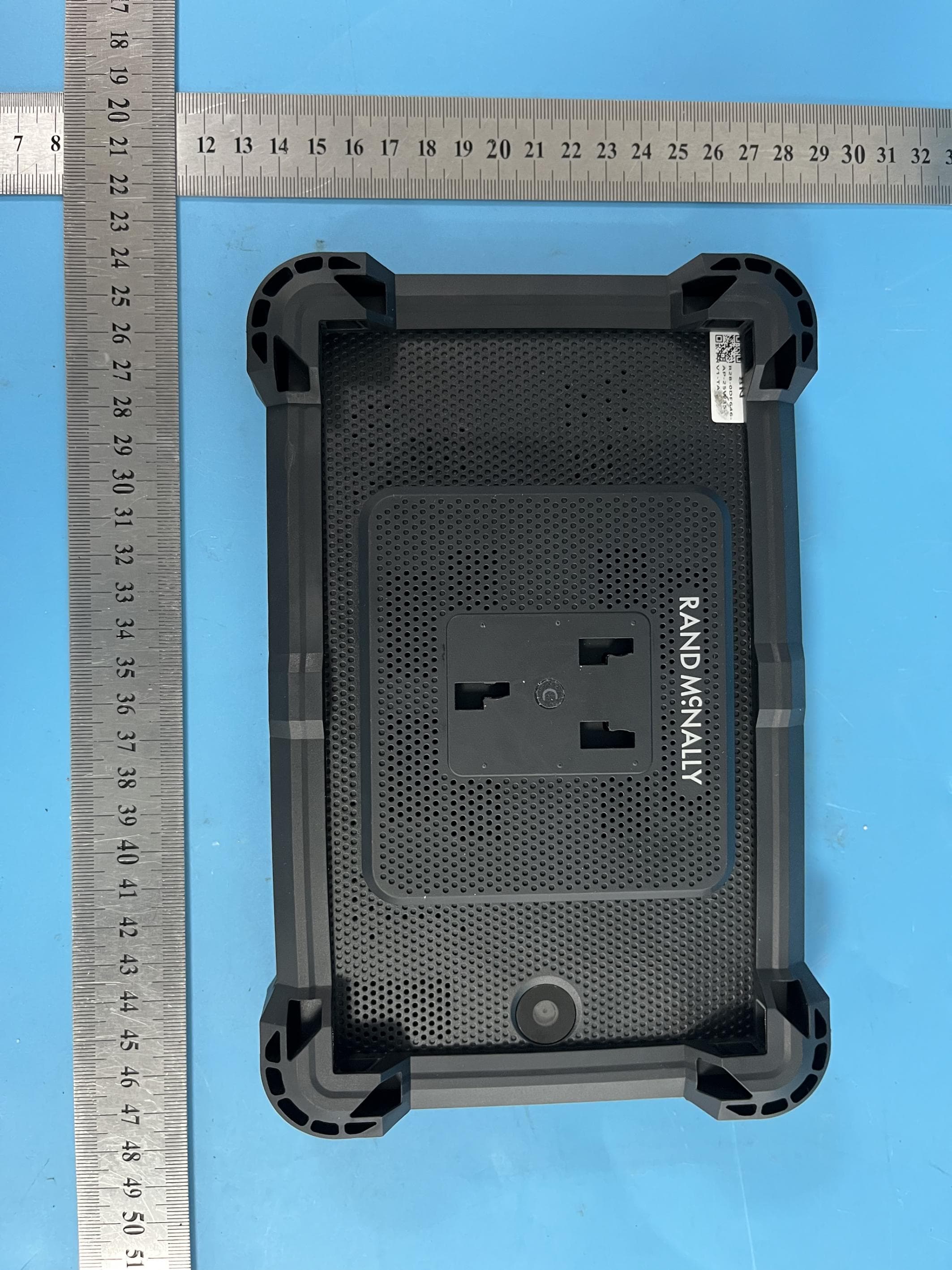
A4C-10019A
Dec 19, 2025GPS Device
Equipment Class
DSS - Part 15 Spread Spectrum Transmitter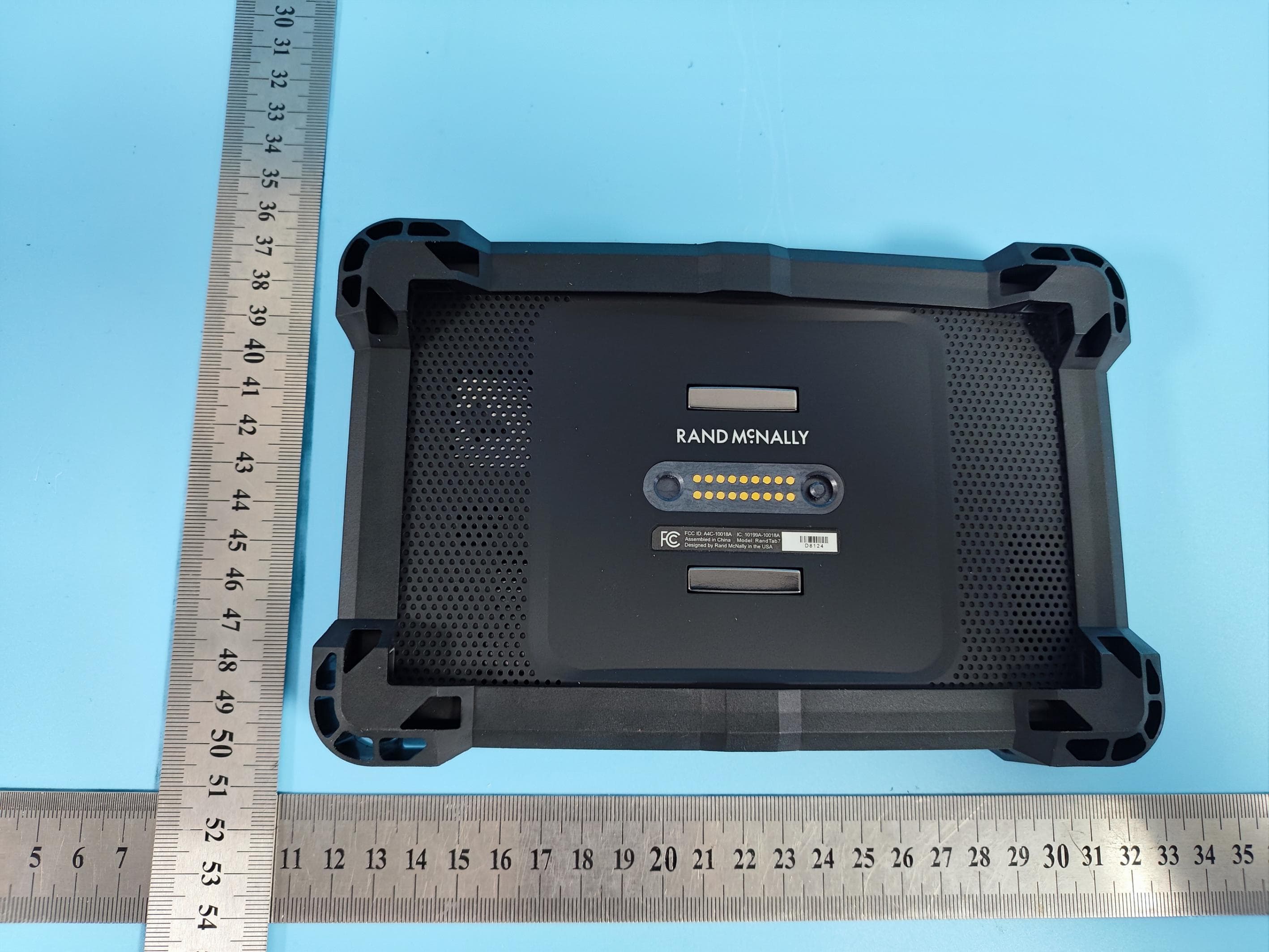
A4C-10018A
Dec 17, 2025GPS Device
Equipment Class
NII - Unlicensed National Information Infrastructure TX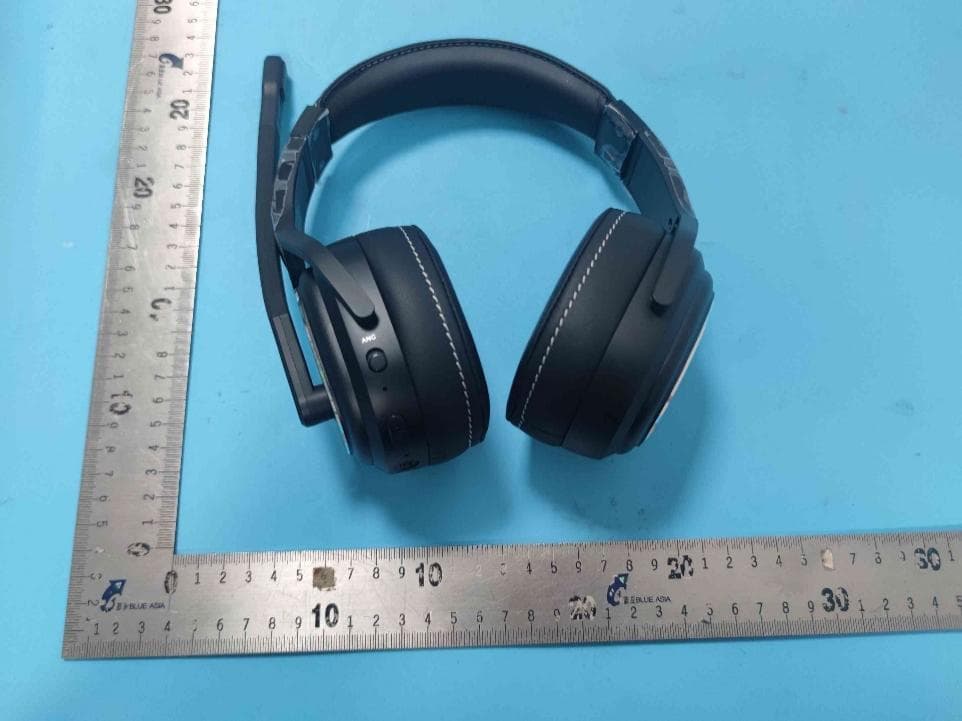
A4C91008B
Sep 26, 2024Bluetooth ANC Headset CD220S
Equipment Class
DSS - Part 15 Spread Spectrum Transmitter
A4C-10017A
Aug 12, 2024GPS navigator
Equipment Class
NII - Unlicensed National Information Infrastructure TX
A4C-10011B
Sep 04, 2023GPS Device
Equipment Class
NII - Unlicensed National Information Infrastructure TX