A4C01002ATruck Information Terminal
RM Acquisition LLC.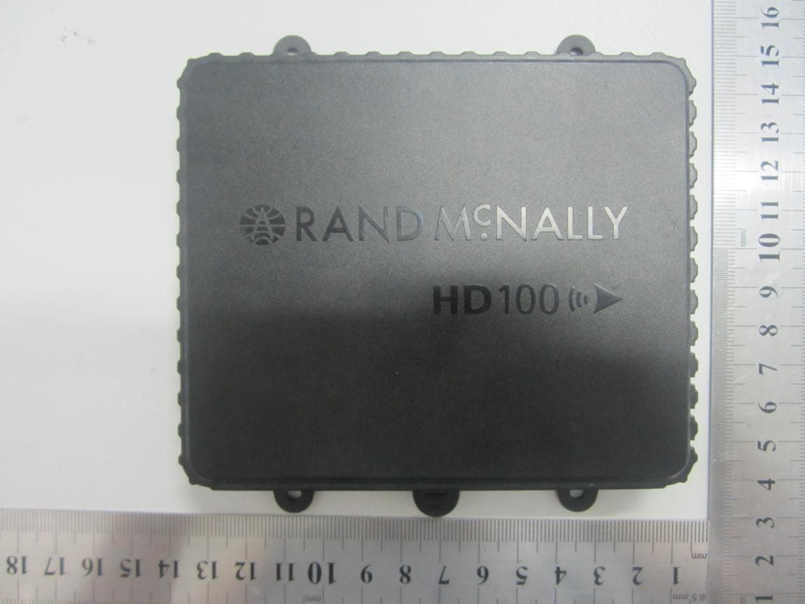
Click to zoom
Application Details
- Equipment Class
- PCB - PCS Licensed Transmitter
- Date of Grant
- Jul 24, 2013
- Application Purpose
- Original Equipment
- Date of Application
- Jul 24, 2013
- Equipment Note
- Truck Information Terminal
- Frequency Range
- 1851.25000000 - 1908.75000000
- Company
- RM Acquisition LLC.
- Country
- United States
Documents & Files
Document Text
Text extracted from the exhibit documents filed with the FCC. Open a document above to read the original.
Users Manual
User Manual 2 HD 100 UserManual Support Call us: 1-800-641-RAND (7263) E- ail us: [email protected] Write to us: Rand McNally Attn: HD 100 ® Customer Support 106 Hi-Lane Richmond, KY 40475 Safe Driving Practices: This product is powered by lead-acid battery Always use your best judgment, exercise caution and common sense ,Don’t Short C ircuit. when the vehicle is in motion. Do not become distracted by the device while driving. Minimize the amount of time spent looking at the device while driving and use voice prompts when possible. When using the device, maintain a distance of Do not input destinations, change settings, or access any functions 20cm from the body to ensure compliance with requiring prolonged use of the device controls while driving. Pull over in RF exposure requirements. a safe and legal manner before attempting such operations. 2 HD 100 UserManual HD 100 User Manual 3 FCC Compliance Statement This device complies with part 15 of the FCC rules. to the following two conditions: (1) this device may not cause harmful Operation is subject interference, and (2) this device must accept any interference received, including interference that may cause undesired operation. This equipment has been tested and found to comply with the limits for a Class B digital device, pursuant to part 15 of the FCC rules. These limits are designed to provide reasonable protection against harmful interference in a residential installation. This equipment generates, uses, and can radiate radio frequency energy and may cause harmful interference to radio communications if not installed and used in accordance with the instructions. However, there is no guarantee that interference will not occur in a particular installation. If this equipment does cause harmful interference to radio or television reception, which can be determined by turning the equipment off and on, the user is encouraged to try to correct the interference by one of the following measures: Reorient or relocate the receiving antenna. Increase the separation between the equipment and the receiver. Connect the equipment into an outlet that is on a different circuit from the telematics unit. Consult the dealer or an experienced radio/TV technician for help. NOTE: The manufacturer is not responsible for any radio or TV interference caused by unauthorized modifications or changes to this equipment. Such modifications or changes could void the user’s authority to operate the equipment. 4 HD 100 UserManual Table of Contents Activating Your HD 100 for the First Time ................................... 5 Download Dock ....................................................................... 5 Connect HD 100 ...................................................................... 6 Activate Service Plan ................................................................. 6 Configure Account Settings ......................................................... 6 Connect TND ™ 720 ................................................................... 6 Installing Your HD 100 ............................................................... 7 Installation Kit ......................................................................... 7 Installation Instructions ............................................................ 7-8 Alternative Install Options .......................................................... 8 Quick Diagnostics ..................................................................... 8 Troubleshooting .................................................................. 9-11 Accessing the Connect Web Portal ............................................. 12 Log On ................................................................................. 12 Feature Overview ................................................................ 13-14 Using the HD 100 Software ...................................................... 15 Getting Started ....................................................................... 15 Power On .......................................................................... 15 Log On ............................................................................. 15 Warning Screen ................................................................... 16 On-screen Keyboard ................................................................. 17 Status Bar .......................................................................... 18 Screen Calibration ................................................................ 19 HD 100 Home Menu ............................................................... 20 Home Menu Safe-driving Screen .............................................. 21 HD 100 Mail ......................................................................................... 22 Inbox ............................................................................................... 23 Open Message .......................................................................................... 24 Outbox ............................................................................................ 25 Send Messages ........................................................................................... 26 Options ............................................................................................ 27 Mail Safe-driving Screen ........................................................................ 27 HD 100 Hours of Service ............................................................................ 28 Summary .......................................................................................... 29-30 Duty Status ....................................................................................... 31-35 Logs .................................................................................................... 36-38 DVIR .......................................................................................... 39-42 Options .........…
Text truncated - open the document above for the full version.
Cover Letter(s)
Date: June 18, 2013 To: Federal Communications Commission, Authorization & Evaluation Division, 7435 Oakland Mills Road, Columbia, MD 21046 Re: RM Acquisition LLC FCC ID: A4C-01002A FCC Part 15C&22&24 Certification Confidentiality Request Gentlemen: This letter is to comply with 47 CFR 0.457 and 0.459 pertaining to confidentiality material. RM Acquisition LLC requests that the following documents regarding this submission for FCC ID: A4C-01002A be kept confidential: Exhibit Type File Name Block Diagram Block Diagram.pdf Schematics Circuit Diagram.pdf Operational Description Tune-Up Operation Description.pdf Tune-Up.pdf Part list BOM.pdf Those documents contain detailed system and equipment description and related information about the product which A4C-01002A considers to be confidential proprietary, a custom design and, otherwise, not releasable to the general public. Since this design is a basis form which future technological products will evolve, RM Acquisition LLC considers this information would be of benefit to its competitors, and that the disclosure of the information in these documents would give competitors an unfair advantage in the market.
External Photos
External Photos 1. EUT front view 2. EUT rear view 3. EUT left side view 4. EUT right side view 5. EUT top view 6. EUT bottom view
ID Label/Location Info
FCC ID: A4C-01002A Label Label Location
Internal Photos
Internal Photos 1. Mainboard front view with shielding 2. Mainboard rear view with shielding 3. Mainboard front view without shielding 4. Mainboard rear view without shielding 5. CDMA chip view 6. CPU chip view 7. WIFI chip view 8. GPS chip view 9. CDMA antenna view 10. WIFI antenna view 11. GPS antenna view
RF Exposure Info
SZ13040100S01 Page 2 of 9 DIRECTORY DIRECTORY....................................................................................................................................2 1.TESTING LABORATORY..........................................................................................................3 1.1. Identification of the Responsible Testing Location.....................................................................3 1.2. Accreditation Certificate..............................................................................................................3 2.TECHNICAL INFORMATION...................................................................................................4 2.1. Identification of Applicant...........................................................................................................4 2.2. Identification of Manufacturer.....................................................................................................4 2.3. Equipment Under Test (EUT)......................................................................................................4 2.3.1. Photographs of the EUT............................................................................................................4 2.3.2. Identification of all used EUT...................................................................................................4 2.4. Applied Reference Documents.................................................................................................... 5 3. DEVICE CATEGORY AND RF EXPOSURE LIMIT.............................................................6 4. MEASUREMENT OF CONDUCTED PEAK OUTPUT POWER......................................... 7 5. RF EXPOSURE EVALUATION................................................................................................ 8 Change History IssueDateReason for change 1.0Jul. 19, 2013First edition SZ13040100S01 Page 3 of 9 1. Testing Laboratory 1.1. Identification of the Responsible Testing Location Name:Shenzhen Morlab Communications Technology Co., Ltd. Morlab Laboratory Address:FL.3, Building A, FeiYang Science Park, No.8 LongChang Road, Block 67, BaoAn District, ShenZhen, GuangDong Province, P. R. China 518101 FCC Registration Number:695796 1.2. Accreditation Certificate Accredited Testing Laboratory:No. CNAS L3572 SZ13040100S01 Page 4 of 9 2.Technical Information Note: the following data is based on the information by the applicant. 2.1. Identification of Applicant Company Name:RM Acquisition LLC Address:9855 Woods Drive, Skokie, Illinos 60077 2.2. Identification of Manufacturer Company Name:SHENZHEN LONGHORN AUTOMATIC ELECTRONICS EQUIPMENT CO., LTD. Address: LONGHORN HI-TECH ESTATE, GONGYEYUAN RD., DALANG STREET, BAOAN, SHENZHEN, CHINA 2.3. Equipment Under Test (EUT) Model Name:HD100 Trade Name:RAND MCNALLY Brand Name:RAND MCNALLY Hardware Version:V4.0 Software Version:V4.0 Frequency Bands:CDMA 800MHz / CDMA 1900MHz; 802.11 b/g/n; Modulation Mode:CDMA:CDMA; 802.11 b: DSSS; 802.11g: OFDM; 802.11n: OFDM; Antenna type:External Monopole Antenna Development Stage:Identical prototype Battery Model:N/A Battery specification:N/A 2.3.1. Photographs of the EUT Please see for photographs of the EUT. 2.3.2. Identification of all used EUT The EUT identity consists of numerical and letter characters, the letter character indicates the test sample, and the following two numerical characters indicate the software version of the test sample. EUT Identity Hardware VersionSoftware Version 1#V4.0V4.0 SZ13040100S01 Page 5 of 9 2.4. Applied Reference Documents Leading reference documents for testing: No.IdentityDocument Title 147 CFR§2.1091Radiofrequency Radiation Exposure Evaluation: mobile devices 247CFR§ 1.1310Radiofrequency radiation exposure limits 2KDB 447498 D01General RF Exposure Guidance v05 SZ13040100S01 Page 6 of 9 3. Device Category and RF Exposure Limit Per user manual, this device is a Truck Information Terminal within car use. Based on 47CFR 2.1091, this device belongs to mobile device category with General Population/Uncontrolled exposure. Mobile Devices: 47 CFR § 2.1091(b) For purposes of this section, a mobile device is defined as a transmitting device designed to be used in other than fixed locations and to generally be used in such a way that a separation distance of at least 20 centimeters is normally maintained betweenthe transmitter's radiating structure(s) and the body of the user or nearby persons. In this context, the term “ fixed location ” means that the device is physically secured at one location and is not able to be easily moved to another location. Transmitting devices designed to be used by consumers or workers that can be easily re-located, such as wireless devices associated with a personal computer, are considered to be mobile devices if they meet the 20 centimeter separation requirement. 47CFR § 1.1310 GENERAL POPULATION / UNCONTROLLED EXPOSURE The general population/uncontrolled exposure limits are applicable to situations in which the general public may be exposed or in which persons who are exposed as a consequence of their employment may not be made fully aware of the potential for exposure or cannot exercise control over their exposure. Members of the general public would come under this category when exposure is not employment-related; for example, in the case of a wireless transmitter that exposes persons in its vicinity. Warning labels placed on low-power consumer devices such as cellular telephones are not considered sufficient to allow the device to be considered under the occupational/controlled category, and the general population/uncontrolledexposure limits apply to these devices. TABLE1 — LIMITS FORMAXIMUMPERMISSIBLEEXPOSURE(MPE) Frequency range (MHz) Electric field strength (V/m) Magnetic field strength (A/m) Power density (mW/cm 2 ) Averaging time (minutes) (B) Limits for General Population/Uncontrolled Exposure 0.3-1.346141.63*(100)30 1.34-30824/f2.19/f*(180/f 2 )30 …
Text truncated - open the document above for the full version.
Test Report
Report No.: SZ13040100W01 Page 2 of 43 TABLE OF CONTENTS 1. GENERAL INFORMATION .................................................................................................... 3 1.1 EUT Description ......................................................................................................................... 3 1.2 Test Standards and Results ........................................................................................................ 4 1.3 Facilities and Accreditations ...................................................................................................... 5 2. 47 CFR PART 2, PART 22H & 24E REQUIREMENTS ........................................................ 6 2.1 Conducted RF Output Power .................................................................................................... 6 2.2 Peak to Average Radio.............................................................................................................. 14 2.3 99% Occupied Bandwidth ....................................................................................................... 17 2.4 Frequency Stability ................................................................................................................... 21 2.5 Conducted Out of Band Emissions ......................................................................................... 23 2.6 Band Edge ................................................................................................................................. 30 2.7 Transmitter Radiated Power (EIRP/ERP) ............................................................................. 33 2.8 Radiated Out of Band Emissions ............................................................................................ 37 Change History Issue Date Reason for change 1.0 Jul 19, 2013 First edition Report No.: SZ13040100W01 Page 3 of 43 1. GENERAL INFORMATION 1.1 EUT Description EUT Type ............................. : Truck Information Terminal Model Name ......................... : HD100 Serial No. ............................. : (n.a, marked #1 by test site) Hardware Version ................. : V4.0 Software Version .................. : Applicant .............................. : Manufacturer ........................ : V4.0 RM Acquisition LLC 9855 Woods Drive, Skokie, Illinos 60077 SHENZHEN LONGHORN AUTOMATIC ELECTRONICS EQUIPMENT CO., LTD. LONGHORN HI-TECH ESTATE,GONGYEYUAN RD., DALANG STREET,BAOAN, SHENZHEN, CHINA Frequency Range.................. : CDMA 800MHz: Tx: 824.7-848.31 MHz; Rx: 869.7-893.31MHz CDMA 1900MHz: Tx: 1851.25 MHz-1908.75 MHz; Rx: 1931.25 MHz-1988.75 MHz Modulation Type .................. : CDMA 1X Emission Designators ........... : 1M28F9W Modulation Type .................. : Chip Antenna Note 1: The EUT is a HD100 Truck Information Terminal operating in Cellular and PCS bands. Note 2: The normal configuration for the EUT is the Mobile Phone (MS) associated with ancillary equipments e.g. the Battery and/or the AC Adapter (Charger). Note 3: For a more detailed description, please refer to Specification or User’s Manual supplied by the applicant and/or manufacturer. Report No.: SZ13040100W01 Page 4 of 43 1.2 Test Standards and Results The objective of the report is to perform testing according to: No. Identity Document Title 1 47 CFR Part 2 (10-1-09 Edition) Frequency Allocations and Radio Treaty Matters; General Rules and Regulations 2 47 CFR Part 22 (10-1-09 Edition) Public Mobile Services 3 47 CFR Part 24 (10-1-09 Edition) Personal Communications Services Test detailed items/section required by FCC rules and results are as below: N o. Section in CFR Description Test Band Result 1 2.1046 22.913(a) 24.232 Conducted RF Output Power CDMA 800/1900MHz PASS 2. 24.232(d), Peak to average radio CDMA 800/1900MHz PASS 3 2.1049 Occupied Bandwidth CDMA 800/1900MHz PASS 4 2.1055 22.355 24.235 Frequency Stability CDMA 800/1900MHz PASS 5 2.1051 2.1057 22.917 24.238 Conducted Out of Band Emissions CDMA 800/1900MHz PASS 6 2.1051 2.1057 22.917 24.238 Band Edge CDMA 800/1900MHz PASS 7 22.913 24.232 Transmitter Radiated Power (EIPR/ERP) CDMA 800/1900MHz PASS 8 2.1053 2.1057 22.917 24.238 Radiated Out of Band Emissions CDMA 800/1900MHz PASS NOTE:Measurement method according to ANSI/TIA-603-D 2010. Report No.: SZ13040100W01 Page 5 of 43 1.3 Facilities and Accreditations 1.3.1 Facilities Shenzhen Morlab Communications Technology Co., Ltd. Morlab Laboratory is a testing organization accredited by China National Accreditation Service for Conformity Assessment (CNAS) according to ISO/IEC 17025. The accreditation certificate number is L3572. All measurement facilities used to collect the measurement data are located at 3/F, Electronic Testing Building, Shahe Road, Xili, Nanshan District, Shenzhen, 518055 P. R. China. The test site is constructed in conformance with the requirements of ANSI C63.7, ANSI C63.4 and CISPR Publication 22; the FCC registration number is 741109. 1.3.2 Test Environment Conditions During the measurement, the environmental conditions were within the listed ranges: Temperature (°C): 15 - 35 Relative Humidity (%): 30 -60 Atmospheric Pressure (kPa): 86-106 Report No.: SZ13040100W01 Page 6 of 43 2. 47 CFR PART 2, PART 22H & 24E REQUIREMENTS 2.1 Conducted RF Output Power 2.1.1 Requirement According to FCC section 2.1046(a), for transmitters other than single sideband, independent sideband and controlled carrier radiotelephone, power output shall be measured at the RF output terminals when the transmitter is adjusted in accordance with the tune-up procedure to give the values of current and voltage on the circuit elements specified 2.1.2 Test Description 1. Test Setup: The EUT, which is powered by the Battery, is coupled to the Spectrum Analyzer (SA) and the System Simulator (SS) with Attenuators through the Power Splitter; the RF load attached to the EUT antenna terminal is 50Ohm; the path loss as the factor is calibrated to correct the rea…
Text truncated - open the document above for the full version.
Test Setup Photos
Test Setup Photos 1. Conducted Spurious Emission 2. Radiated Spurious Emission
Contact Information
Applicant
Kristalyn Wilkerson(CFO)
Technical Contact
Shenzhen Morlab Communications Technology Co.,LtdIvy Zhu
[email protected]86-755-36698618
FL.3, Building A, FeiYang Science Park · ShenZhen, GuangDong Province · China
Test Firm
Shenzhen Morlab Communications Technology Co., LtdIvy zhu
Technical Specifications
| # | Rule Parts | Frequency Range | Power Output | Emission | Tolerance |
|---|---|---|---|---|---|
| 2 | 24E | 1.85 GHz - 1.91 GHz | 162.00 mW | 1M28F9W | 0.01 ppm |
Other Applications from RM Acquisition LLC.
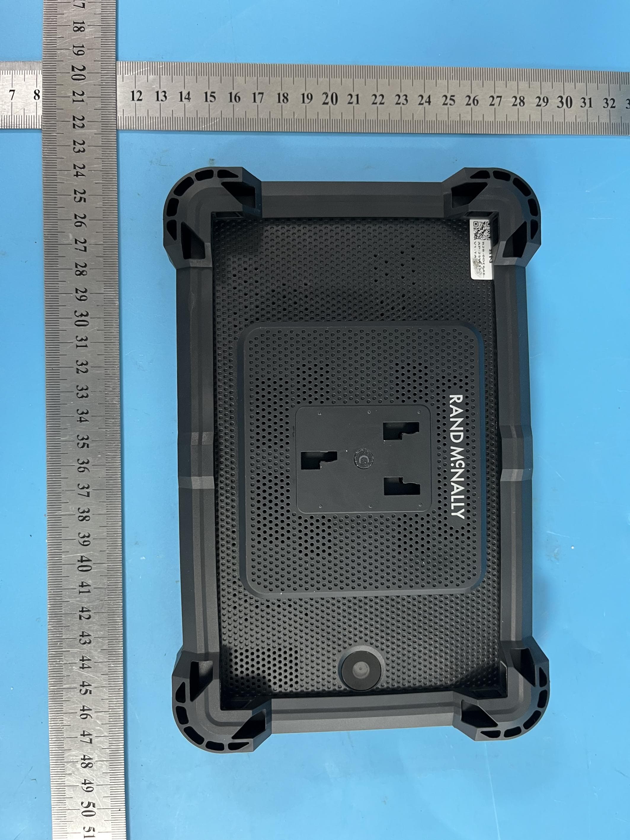
A4C-10019A
Dec 19, 2025GPS Device
Equipment Class
DSS - Part 15 Spread Spectrum Transmitter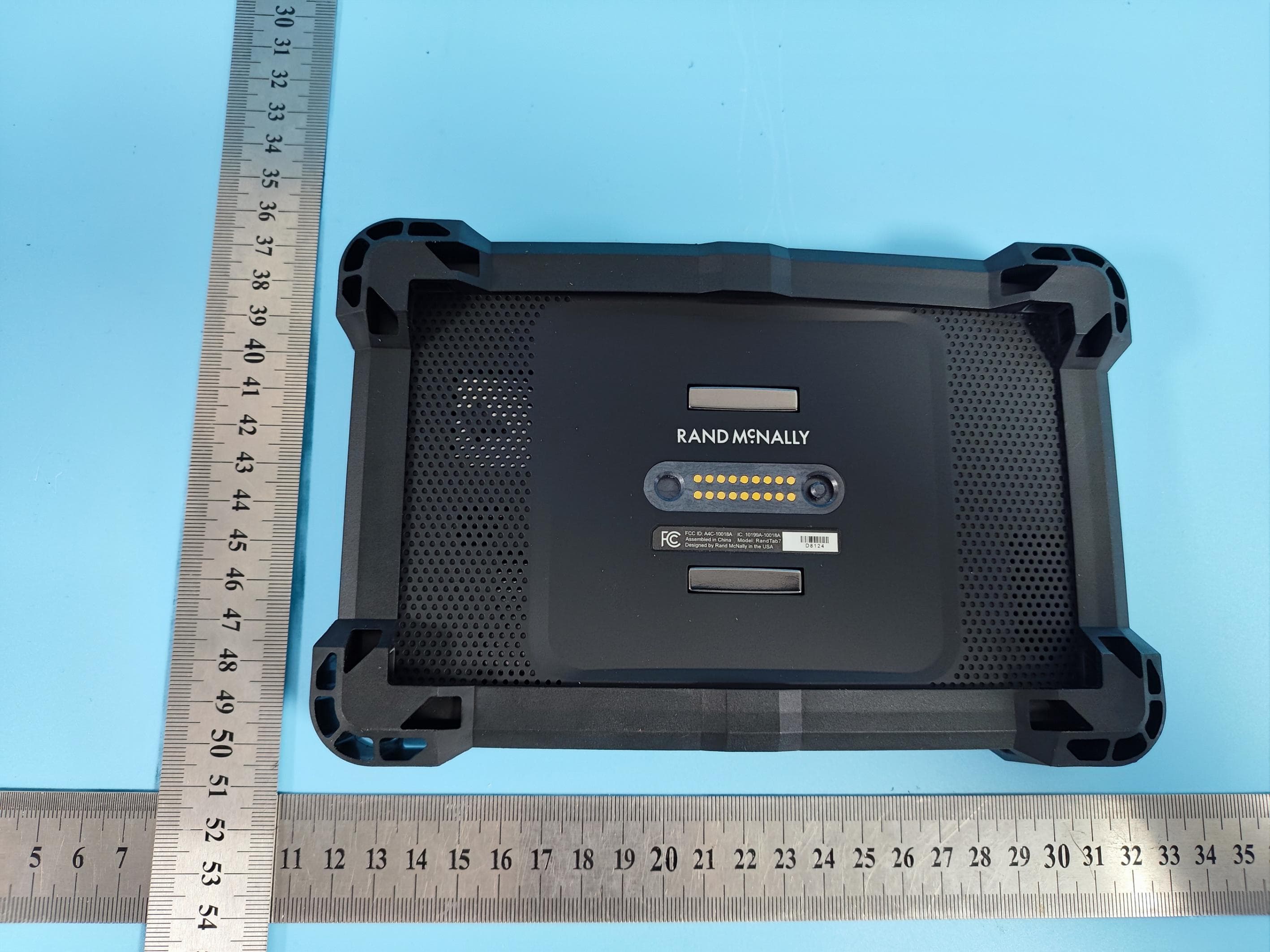
A4C-10018A
Dec 17, 2025GPS Device
Equipment Class
NII - Unlicensed National Information Infrastructure TX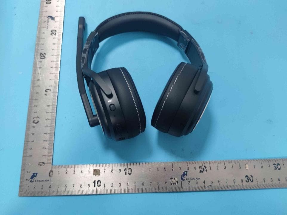
A4C91008B
Sep 26, 2024Bluetooth ANC Headset CD220S
Equipment Class
DSS - Part 15 Spread Spectrum Transmitter
A4C-10017A
Aug 12, 2024GPS navigator
Equipment Class
NII - Unlicensed National Information Infrastructure TX
A4C-10011B
Sep 04, 2023GPS Device
Equipment Class
NII - Unlicensed National Information Infrastructure TX