A4HRWRFIDLCD Rear Display w/RFID Series 2
Oracle America, Inc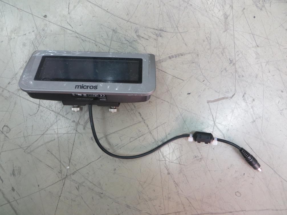
Click to zoom
Application Details
- Equipment Class
- DXT - Part 15 Low Power Transceiver, Rx Verified
- Date of Grant
- Feb 18, 2014
- Application Purpose
- Original Equipment
- Date of Application
- Feb 15, 2014
- Equipment Note
- LCD Rear Display w/RFID Series 2
- Frequency Range
- 13.56000000 - 13.56000000
- Company
- Oracle America, Inc
- Country
- United States
Documents & Files
Document Text
Text extracted from the exhibit documents filed with the FCC. Open a document above to read the original.
Users Manual
Key Information The new designed MICROS customer display implements the NFC function. The Rear Display is attached to MICROS POS docking station- mStation. The Pole Display stands alone the mStation. Except the normal display function, both new models have NFC function. Specification Model LCD Rear Display w/RFID Series 2 LCD Pole Display w/RFID Series 2 Overall Dimension (not including mounting fixture) 63.2 x 135.9 x 29.3mm LCD module size 37 x 116 x12.9mm Backlight LED Backlight Number of character 20CH x 2 Lines Power in DC 5V from mStation customer display port Rating DC 5V, 250mA max. Max. Operating Temperature 65°C NFC Function YES Product final location Installing of LCD Pole Display w/RFID Series 2 As above picture shown, fix the position of the pole display (beside the mStation), and connect the cable to mStation customer display port. Installing of LCD Rear Display w/RFID Series 2 The following procedure describes how to attach the Rear LCD Customer Display (LCD Rear Display Series 2) to the MICROS mStation. The customer display is provided as a complete assembly ready to install. 1. Remove the AC power cable from the mStation. 2. Place the mStation face down. Find the 2 screw holes for attach LCD customer display, which at the edge of unit. 3. Attach the LCD customer display to it and tighten the captive screws as shown in figure 1. Figure 1 4. Feed the interface cable to IO port labeled “Customer Display” 5. Snap-in the cable to the clip and rubber footer. And then use cable tie to fix the cable inside the concave as shown in figure 2. Figure 2 Tighten the captive screws mStation Customer Display Rubber footer Cli p Cable tie to fix the cable in concave 6. Return the mStation to the normal operating position, connect the AC power cord and press the power button. The Integrated LCD Customer Display is automatically detected. Figure 3 Test the Customer Display 1. From the Window Embedded Compact 7 Desktop, go to MyDevice > Boot > Utilities > Diagutility_Vienna. The[Micros Diagnostic] screen displayed. 2. Press the “Customer Display” icon, • Select display data • Click [Send] or [Full Update] button 3. The text message displayed on the customer display screen. 4. NFC function • Put the card near the rear display or pole display • Display NFC antenna will sense the card and transfer the data to the mTablet. Caution: This device complies with Part 15 of the FCC Rules / Industry Canada licence-exempt RSS standard(s). Operation is subject to the following two conditions: (1) this device may not cause harmful interference, and (2) this device must accept any interference received, including interference that may cause undesired operation. Le présent appareil est conforme aux CNR d'Industrie Canada applicables aux appareils radio exempts de licence. L'exploitation est autorisée aux deux conditions suivantes : (1) l'appareil ne doit pas produire de brouillage, et (2) l'utilisateur de l'appareil doit accepter tout brouillage radioélectrique subi, même si le brouillage est susceptible d'en compromettre le fonctionnement. Changes or modifications not expressly approved by the party responsible for compliance could void the user's authority to operate the equipment. This equipment has been tested and found to comply with the limits for a Class B digital device, pursuant to part 15 of the FCC Rules. These limits are designed to provide reasonable protection against harmful interference in a residential installation. This equipment generates uses and can radiate radio frequency energy and, if not installed and used in accordance with the instructions, may cause harmful interference to radio communications. However, there is no guarantee that interference will not occur in a particular installation. If this equipment does cause harmful interference to radio or television reception, which can be determined by turning the equipment off and on, the user is encouraged to try to correct the interference by one or more of the following measures: —Reorient or relocate the receiving antenna. —Increase the separation between the equipment and receiver. —Connect the equipment into an outlet on a circuit different from that to which the receiver is connected. —Consult the dealer or an experienced radio/TV technician for help. Under Industry Canada regulations, this radio transmitter may only operate using an antenna of a type and maximum (or lesser) gain approved for the transmitter by Industry Canada. To reduce potential radio interference to other users, the antenna type and its gain should be so chosen that the equivalent isotropically radiated power (e.i.r.p.) is not more than that necessary for successful communication. Conformément à la réglementation d'Industrie Canada, le présent émetteur radio peut fonctionner avec une antenne d'un type et d'un gain maximal (ou inférieur) approuvé pour l'émetteur par Industrie Canada. Dans le but de réduire les risques de brouillage radioélectrique à l'intention des autres utilisateurs, il faut choisir le type d'antenne et son gain de sorte que la puissance isotrope rayonnée équivalente (p.i.r.e.) ne dépasse pas l'intensité nécessaire à l'établissement d'une communication satisfaisante.
Cover Letter(s)
MICROS SYSTEMS, INC
Cover Letter(s)
MICROS SYSTEMS, INC 12-28-2014
External Photos
FCC ID: A4HRWRFID IC: 9870A-RWRFID Page 1 of 3 External Picture FCC ID: A4HRWRFID IC: 9870A-RWRFID Page 2 of 3 FCC ID: A4HRWRFID IC: 9870A-RWRFID Page 3 of 3 EUT together with peripherals LCD Rear Display w/RFID Series 2 mTablet mStation
ID Label/Location Info
Product Label and FCC Statement label Artwork Dimension: 46 mm (L) x 16 mm (H) Round angle, Black background, White font Drawing Ratio: 2:1 Dimension: 50 mm (L) x 12 mm (H) Round angle Drawing Ratio: 2:1 The label would be silkscreened or engraved on the location as below: 14 cm 7 cm
Internal Photos
FCC ID: A4HRWRFID IC: 9870A-RWRFID Page 1 of 4 Internal Picture FCC ID: A4HRWRFID IC: 9870A-RWRFID Page 2 of 4 FCC ID: A4HRWRFID IC: 9870A-RWRFID Page 3 of 4 FCC ID: A4HRWRFID IC: 9870A-RWRFID Page 4 of 4
Test Report
FCC ID: A4HRWRFID IC: 9870A-RWRFID Page 1 of 27 EMC TEST REPORT No. 130900812SHA-001 Applicant : MICROS Systems Inc 7031 Columbia Gateway Dr, Columbia, 21046 MD, USA Manufacturer : GES Singapore Pte Ltd 28 Marsiling Lane, Singapore 739152 Product Name : LCD Rear Display Type/Model : LCD Rear Display w/RFID Series 2 SUMMARY The equipment complies with the requirements according to the following standard(s): 47CFR Part 15 (2012): Radio Frequency Devices RSS 210 (Issue 8, December 2010): Licence-exempt Radio Apparatus (All Frequency Bands): Category I Equipment RSS-Gen (Issue 3, December 2010): General Requirements and Information for the Certification of Radio Apparatus ANSI C63.4 (2009): American National Standard for Methods of Measurement of Radio-Noise Emissions from Low-Voltage Electrical and Electronic Equipment in the Range of 9 kHz to 40 GHz ANSI C63.10 (2009): American National Standard for Testing Unlicensed Wireless Devices Date of issue: Jan 5, 2014 Prepared by: Reviewed by: Wakeyou Wang (Project Engineer) Daniel Zhao (Reviewer) FCC ID: A4HRWRFID IC: 9870A-RWRFID Page 2 of 27 Description of Test Facility Name: Intertek Testing Services Limited Shanghai Address: Building No.86, 1198 Qinzhou Road(North), Shanghai 200233, P.R. China FCC Registration Number: 236597 IC Assigned Code: 2042B-1 Name of contact: Steve Li Tel: +86 21 64956565 ext. 214 Fax: +86 21 54262335 ext. 214 FCC ID: A4HRWRFID IC: 9870A-RWRFID Page 3 of 27 Content SUMMARY .......................................................................................................................................................... 1 DESCRIPTION OF TEST FACILITY ......................................................................................................................... 2 1. GENERAL INFORMATION ............................................................................................................................ 4 1.1 Applicant Information ..................................................................................................... 4 1.2 Identification of the EUT ................................................................................................ 4 1.3 Technical specification ................................................................................................... 5 1.4 Mode of operation during the test / Test peripherals used .............................................. 5 2. TEST SPECIFICATION .................................................................................................................................. 6 2.1 Instrument list ................................................................................................................. 6 2.2 Test Standard .................................................................................................................. 6 3. FUNDAMENTAL EMISSION ........................................................................................................................... 8 3.1 Test limit ......................................................................................................................... 8 3.2 Test Configuration .......................................................................................................... 8 3.3 Test procedure and test setup .......................................................................................... 8 3.4 Test protocol ................................................................................................................... 9 4. SPURIOUS EMISSION .................................................................................................................................. 10 4.1 Test limit ....................................................................................................................... 10 4.2 Test Configuration ........................................................................................................ 10 4.3 Test procedure and test setup ........................................................................................ 11 4.4 Test protocol ................................................................................................................. 12 5. FREQUENCY STABILITY (TEMPERATURE VARIATION) ............................................................................ 18 5.1 Test limit ....................................................................................................................... 18 5.2 Test Configuration ........................................................................................................ 18 5.3 Test procedure and test setup ........................................................................................ 18 5.4 Test protocol ................................................................................................................. 19 6. FREQUENCY STABILITY (VOLTAGE VARIATION) .................................................................................... 20 6.1 Test limit ....................................................................................................................... 20 6.2 Test Configuration ........................................................................................................ 20 6.3 Test procedure and test setup ........................................................................................ 20 6.4 Test protocol ................................................................................................................. 21 7. POWER LINE CONDUCTED EMISSION ........................................................................................................ 22 7.1 Limit .............................................................................................................................. 22 7.2 Test configuration ......................................................................................................... 22 7.3 Test procedure and test set up ...........…
Text truncated - open the document above for the full version.
Test Setup Photos
FCC ID: A4HRWRFID IC: 9870A-RWRFID Page 1 of 3 Test Setup FCC ID: A4HRWRFID IC: 9870A-RWRFID Page 2 of 3 1. Radiated Emission EUT FCC ID: A4HRWRFID IC: 9870A-RWRFID Page 3 of 3 2. Conducted Emission EUT
Contact Information
Applicant
Justin Pearlman(Vice President, Global Trade Compliance)
Technical Contact
Intertek Testing Services Limited ShanghaiWakeyou Wang
[email protected]86-21-61278448
Building No.86,1198 Qinzhou Road(North) · Shanghai · China
Test Firm
Intertek Testing Services Limited ShanghaiJonny Jing
Technical Specifications
| # | Rule Parts | Frequency Range | Power Output |
|---|---|---|---|
| 1 | 15C | 13.56 MHz - 13.56 MHz | - |
Other Applications from Oracle America, Inc
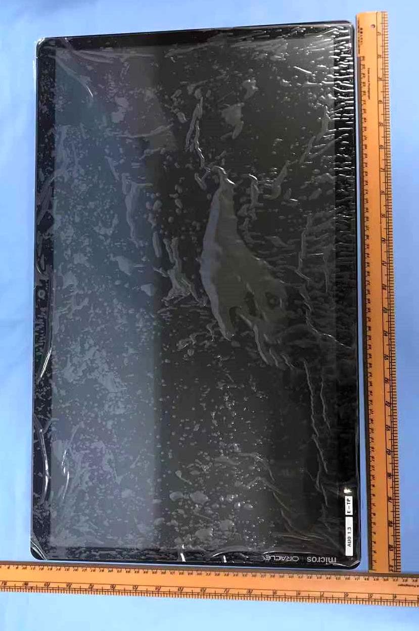
A4HEWS4
Feb 01, 2020MICROS Express Station 4
Equipment Class
DXX - Part 15 Low Power Communication Device Transmitter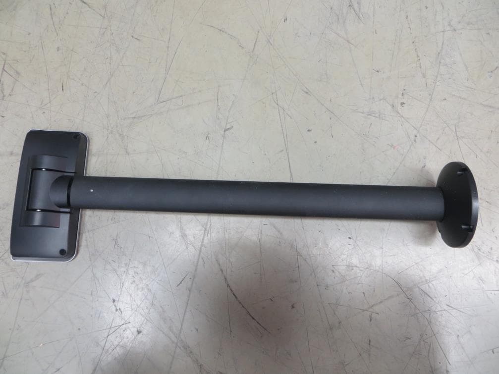
A4HPWRFID
Feb 16, 2014LCD Pole Display w/RFID Series 2
Equipment Class
DXT - Part 15 Low Power Transceiver, Rx Verified
A4HMICROS-WBB10
Jan 10, 2012Wireless Keypad (MWBB-10)
Equipment Class
DTS - Digital Transmission System